EP0383633A1 - Jaucheinjektor für den Boden - Google Patents
Jaucheinjektor für den Boden Download PDFInfo
- Publication number
- EP0383633A1 EP0383633A1 EP90301730A EP90301730A EP0383633A1 EP 0383633 A1 EP0383633 A1 EP 0383633A1 EP 90301730 A EP90301730 A EP 90301730A EP 90301730 A EP90301730 A EP 90301730A EP 0383633 A1 EP0383633 A1 EP 0383633A1
- Authority
- EP
- European Patent Office
- Prior art keywords
- blade
- chamber
- slurry
- static
- prime mover
- Prior art date
- Legal status (The legal status is an assumption and is not a legal conclusion. Google has not performed a legal analysis and makes no representation as to the accuracy of the status listed.)
- Withdrawn
Links
Images

Classifications
-
- A—HUMAN NECESSITIES
- A01—AGRICULTURE; FORESTRY; ANIMAL HUSBANDRY; HUNTING; TRAPPING; FISHING
- A01C—PLANTING; SOWING; FERTILISING
- A01C23/00—Distributing devices specially adapted for liquid manure or other fertilising liquid, including ammonia, e.g. transport tanks or sprinkling wagons
- A01C23/001—Sludge spreaders, e.g. liquid manure spreaders
- A01C23/002—Sludge spreaders, e.g. liquid manure spreaders provided with auxiliary arrangements, e.g. pumps, agitators, cutters
Definitions
- This invention relates to the injection of animal manure slurry into soil.
- the aim of the present invention is to provide an improved feeding device for feeding the slurry to injection hoses thus at least mitigating the aforementioned problems.
- a device for distributing manure slurry under pressure from a holding tank to outlets coupled to injector nozzles comprising: a body including a chamber having at least one inlet port and a plurality of outlet ports, a plurality of first blade members affixed within said chamber, at least one said blade member rotatably disposed with said chamber and co-operable with said fixed blade members, a prime mover mounted on said body, and means coupling an output of said prime mover to rotate said second blade member.
- a device according to the invention is used in conjunction with a machine suited to being towed by a tractor over pasture to be treated.
- the machine would typically comprise a chassis including a drawbar for coupling to the tractor.
- the chassis would be mounted on spaced apart wheels which follow the surface of the pasture.
- a number of discs typically seven depend from the chassis and slit the surface of the pasture to a depth of approximately 50mm-75mm as the machine is towed by the tractor.
- a wing-shaped blade is mounted behind each disc and forms a slit or cut under the surface of the soil transverse to the base of the slit cut by the disc.
- the manure slurry is injected into this zone under pressure via an injection nozzle mounted immediately behind the wing-shaped blade.
- the manure slurry is pumped directly from a holding tank under pressure to each of the injection nozzles.
- the major problem with this arrangement is that the tubes supplying the manure to the inejctors become easily blocked due to lumps of material that are present in the slurry.
- the device according to the present invention overcomes this problem and will now be described with reference to this type of machine.
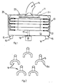
- the device of the invention comprises a casing 10, expediently cylindrical in shape, closed by a top plate or cover, 11 and a bottom plate 12 to define a chamber 13 therein.
- the top plate 11 incorporates a slurry inlet 14, which is preferably at least 125mm in diameter.
- the slurry inlet 14 is coupled to the outlet of a slurry holding tank (not shown) to admit slurry under pressure into the chamber 13.
- a slurry inlet control valve is incorporated, in line, between the slurry holding tank and the inlet 14, in order to allow accurate control of slurry flow to the chamber 13.
- the bottom plate 12 has a planar inner surface which includes a number of outlet ports 15, in this example five, spaced evenly around a desired radius. Each port 15 is coupled to a distribution hose 16 which conveys slurry to an injector (not shown).
- the hoses 16 divide, at bifurcations 16a to provide feed to two separate injectors.
- the cross-sectional area of hose portion 16 is approximately twice that of portion 16a.
- a drive shaft 17 is mounted in bearings, indicated generally at 18, to extend through the bottom plate 12, towards the top plate 11, one end of the drive shaft 17 is coupled to a prime mover assembly 19 mounted on the outside of the casing 10.
- the prime mover expediently comprises a hydraulic motor with an output speed in the vicinity of 900-1500rpm, driven from the hydraulics of the towing tractor.
- the motor may, conveniently, be mounted on a frame (not shown) which also supports the injectors.
- a plurality of static blade members 20 are mounted in stack fashion to the inner wall of the casing.
- the number of static blades may be varied to suit operating conditions. As illustrated, five stacks of blades may be spaced circumferentially about the casing, with each stack consisting of four evenly spaced apart individual blades.
- the blades may be rectangular, triangular, trapezoidal or any other suitable shape.
- a plurality of rotating cutters 21 are mounted in stack fashion for rotating movement on shaft 17.
- each of said five stacks of static blades may contain eight equally spaced individual blades 20. Conveniently spacer members are included between each blade in each stack.
- four blade carriers 22 each support six rotating cutters 21, the cutters extending between corresponding pairs of static blades 20, of each stack.
- a clamping disk 24 mounted at the inner end of the drive shaft 17 acts to retain the blade carriers 22 in position for rotation with the shaft 17.
- Slurry enters the chamber 13 via a manifold 23 and into the chamber via ports (not shown) adjacent the static cutters.
- manure slurry admitted under pressure to the chamber 13 is forced between the series of cooperating static cutters and relating blades and is shredded. Clods of material which would otherwise block the outlet tubes and injectors are shredded by the cutters 20 and blades 21 as the carriers 22 rotate.
- Shredded material exits the chamber 13 via the outlets 15 and passes, under pressure, to inejctors for injection into the soil.
- the device is mounted at a convenient centrally located position on the chassis of the machine and is coupled to receive the manure slurry from the holding tank under pressure. It will be appreciated that the device may be modified by altering the numbers of inlet ports, outlet ports and prime mover specification, without departing from the scope of the invention.
Landscapes
- Life Sciences & Earth Sciences (AREA)
- Engineering & Computer Science (AREA)
- Water Supply & Treatment (AREA)
- Soil Sciences (AREA)
- Environmental Sciences (AREA)
- Fertilizing (AREA)
Applications Claiming Priority (2)
| Application Number | Priority Date | Filing Date | Title |
|---|---|---|---|
| NZ228026 | 1989-02-17 | ||
| NZ22802689 | 1989-02-17 |
Publications (1)
| Publication Number | Publication Date |
|---|---|
| EP0383633A1 true EP0383633A1 (de) | 1990-08-22 |
Family
ID=19922757
Family Applications (1)
| Application Number | Title | Priority Date | Filing Date |
|---|---|---|---|
| EP90301730A Withdrawn EP0383633A1 (de) | 1989-02-17 | 1990-02-16 | Jaucheinjektor für den Boden |
Country Status (1)
| Country | Link |
|---|---|
| EP (1) | EP0383633A1 (de) |
Cited By (4)
| Publication number | Priority date | Publication date | Assignee | Title |
|---|---|---|---|---|
| WO1992006581A1 (en) * | 1989-05-23 | 1992-04-30 | S.H. Watterson (Engineering) Limited | Spreader apparatus |
| EP0520784A1 (de) * | 1991-06-26 | 1992-12-30 | Greentrac Limited | Verbesserungen an Vorrichtungen zum Einbringen von Gülle oder weiteren Flüssigkeiten in den Boden |
| US6142084A (en) * | 1996-02-16 | 2000-11-07 | Hatloe; Jan Kare | Method and device for periodic depositing of liquid manure such as slurry in a soil |
| GB2458570A (en) * | 2008-03-27 | 2009-09-30 | Redrock Engineering Ltd | Slurry distribution apparatus having a stone trap |
Citations (5)
| Publication number | Priority date | Publication date | Assignee | Title |
|---|---|---|---|---|
| DE1020477B (de) * | 1955-11-30 | 1957-12-05 | Christian Oellgaard Jensen | Maschine mit Schlepperantrieb zum Verteilen einer Mischung von zerhacktem Stallduenger und Duengerschlamm |
| CH366415A (de) * | 1957-09-27 | 1962-12-31 | Moertl Schleppergeraetebau | Güllebehälter |
| FR2261697A1 (en) * | 1974-02-25 | 1975-09-19 | Jeulin Claude | Improved manure burying machine - has container, valve, and soil penetration shares |
| FR2325312A1 (fr) * | 1975-09-29 | 1977-04-22 | Lely Nv C Van Der | Dispositif pour mettre sur ou dans le sol des engrais fluides, en particulier des engrais mixtes |
| EP0079018A1 (de) * | 1981-11-05 | 1983-05-18 | Hugo Vogelsang Fass- und Maschinenbau GmbH | Gerät zum Verteilen von Gülle |
-
1990
- 1990-02-16 EP EP90301730A patent/EP0383633A1/de not_active Withdrawn
Patent Citations (5)
| Publication number | Priority date | Publication date | Assignee | Title |
|---|---|---|---|---|
| DE1020477B (de) * | 1955-11-30 | 1957-12-05 | Christian Oellgaard Jensen | Maschine mit Schlepperantrieb zum Verteilen einer Mischung von zerhacktem Stallduenger und Duengerschlamm |
| CH366415A (de) * | 1957-09-27 | 1962-12-31 | Moertl Schleppergeraetebau | Güllebehälter |
| FR2261697A1 (en) * | 1974-02-25 | 1975-09-19 | Jeulin Claude | Improved manure burying machine - has container, valve, and soil penetration shares |
| FR2325312A1 (fr) * | 1975-09-29 | 1977-04-22 | Lely Nv C Van Der | Dispositif pour mettre sur ou dans le sol des engrais fluides, en particulier des engrais mixtes |
| EP0079018A1 (de) * | 1981-11-05 | 1983-05-18 | Hugo Vogelsang Fass- und Maschinenbau GmbH | Gerät zum Verteilen von Gülle |
Cited By (6)
| Publication number | Priority date | Publication date | Assignee | Title |
|---|---|---|---|---|
| WO1992006581A1 (en) * | 1989-05-23 | 1992-04-30 | S.H. Watterson (Engineering) Limited | Spreader apparatus |
| EP0520784A1 (de) * | 1991-06-26 | 1992-12-30 | Greentrac Limited | Verbesserungen an Vorrichtungen zum Einbringen von Gülle oder weiteren Flüssigkeiten in den Boden |
| US5272992A (en) * | 1991-06-26 | 1993-12-28 | Greentrac Limited | Injection apparatus for injecting slurries/liquids into the ground |
| US6142084A (en) * | 1996-02-16 | 2000-11-07 | Hatloe; Jan Kare | Method and device for periodic depositing of liquid manure such as slurry in a soil |
| GB2458570A (en) * | 2008-03-27 | 2009-09-30 | Redrock Engineering Ltd | Slurry distribution apparatus having a stone trap |
| GB2458570B (en) * | 2008-03-27 | 2012-12-19 | Redrock Machinery Ltd | Slurry distribution apparatus |
Similar Documents
| Publication | Publication Date | Title |
|---|---|---|
| US11805716B2 (en) | Tilling apparatus | |
| US6952998B1 (en) | Minimum till seeding knife | |
| US4114815A (en) | Apparatus for conninuting solids in liquids | |
| US5394812A (en) | Injector for polymer placement and a method therefore | |
| US3437061A (en) | Multiple use agricultural implement | |
| EP0322941B2 (de) | Injektionsvorrichtung für Flüssigmist | |
| WO2016015088A1 (en) | Agricultural apparatus and methods | |
| EP0383633A1 (de) | Jaucheinjektor für den Boden | |
| US8584964B2 (en) | Distribution system for liquid manure spreader | |
| US3146740A (en) | Soil chemical distributing device | |
| US4479444A (en) | Manometer apparatus and system for distribution of liquid fertilizers | |
| US6202942B1 (en) | Manure injector system | |
| US2756544A (en) | Method and apparatus for dispensing fertilizers to irrigation water | |
| RU2828848C1 (ru) | Рабочий орган для внутрипочвенного внесения жидких удобрений | |
| JP7840583B2 (ja) | タンク積載式液肥施用装置 | |
| US3174446A (en) | Power-rotated soil penetrating tool | |
| RU2828842C1 (ru) | Рабочий орган для внутрипочвенного внесения жидкости | |
| CN116918533B (zh) | 一种肥料搅拌与种子比例同步输送装置 | |
| NL1004168C2 (nl) | Werkwijze voor het telen van een gewas en machines voor gebruik daarbij. | |
| GB2279220A (en) | Intruducing waste material into the soil. | |
| RU2025931C1 (ru) | Способ внесения удобрений на сенокосах и пастбищах и рабочий орган для его осуществления | |
| CN119655004A (zh) | 用于退化羊草草地的切根装置及修复方法 | |
| Kaasik | Techniques for Application | |
| EP0962127A1 (de) | Vorrichtung zum Bearbeiten von Treibmist | |
| JPS6344801A (ja) | 土壌切削装置 |
Legal Events
| Date | Code | Title | Description |
|---|---|---|---|
| PUAI | Public reference made under article 153(3) epc to a published international application that has entered the european phase |
Free format text: ORIGINAL CODE: 0009012 |
|
| AK | Designated contracting states |
Kind code of ref document: A1 Designated state(s): AT BE CH DE DK ES FR GB IT LI LU NL SE |
|
| 17P | Request for examination filed |
Effective date: 19910221 |
|
| STAA | Information on the status of an ep patent application or granted ep patent |
Free format text: STATUS: THE APPLICATION HAS BEEN WITHDRAWN |
|
| 17Q | First examination report despatched |
Effective date: 19920224 |
|
| 18W | Application withdrawn |
Withdrawal date: 19920213 |