EP0383644B1 - Flacon doseur - Google Patents
Flacon doseur Download PDFInfo
- Publication number
- EP0383644B1 EP0383644B1 EP90400194A EP90400194A EP0383644B1 EP 0383644 B1 EP0383644 B1 EP 0383644B1 EP 90400194 A EP90400194 A EP 90400194A EP 90400194 A EP90400194 A EP 90400194A EP 0383644 B1 EP0383644 B1 EP 0383644B1
- Authority
- EP
- European Patent Office
- Prior art keywords
- chamber
- neck
- opening
- bellows
- dosing bottle
- Prior art date
- Legal status (The legal status is an assumption and is not a legal conclusion. Google has not performed a legal analysis and makes no representation as to the accuracy of the status listed.)
- Expired - Lifetime
Links
Images

Classifications
-
- G—PHYSICS
- G01—MEASURING; TESTING
- G01F—MEASURING VOLUME, VOLUME FLOW, MASS FLOW OR LIQUID LEVEL; METERING BY VOLUME
- G01F11/00—Apparatus requiring external operation adapted at each repeated and identical operation to measure and separate a predetermined volume of fluid or fluent solid material from a supply or container, without regard to weight, and to deliver it
- G01F11/02—Apparatus requiring external operation adapted at each repeated and identical operation to measure and separate a predetermined volume of fluid or fluent solid material from a supply or container, without regard to weight, and to deliver it with measuring chambers which expand or contract during measurement
- G01F11/08—Apparatus requiring external operation adapted at each repeated and identical operation to measure and separate a predetermined volume of fluid or fluent solid material from a supply or container, without regard to weight, and to deliver it with measuring chambers which expand or contract during measurement of the diaphragm or bellows type
-
- B—PERFORMING OPERATIONS; TRANSPORTING
- B65—CONVEYING; PACKING; STORING; HANDLING THIN OR FILAMENTARY MATERIAL
- B65D—CONTAINERS FOR STORAGE OR TRANSPORT OF ARTICLES OR MATERIALS, e.g. BAGS, BARRELS, BOTTLES, BOXES, CANS, CARTONS, CRATES, DRUMS, JARS, TANKS, HOPPERS, FORWARDING CONTAINERS; ACCESSORIES, CLOSURES, OR FITTINGS THEREFOR; PACKAGING ELEMENTS; PACKAGES
- B65D47/00—Closures with filling and discharging, or with discharging, devices
- B65D47/04—Closures with discharging devices other than pumps
- B65D47/06—Closures with discharging devices other than pumps with pouring spouts or tubes; with discharge nozzles or passages
- B65D47/061—Closures with discharging devices other than pumps with pouring spouts or tubes; with discharge nozzles or passages with telescopic, retractable or reversible spouts, tubes or nozzles
- B65D47/063—Closures with discharging devices other than pumps with pouring spouts or tubes; with discharge nozzles or passages with telescopic, retractable or reversible spouts, tubes or nozzles with flexible parts
Definitions
- the present invention relates to a dosing bottle, and more particularly to a bottle, which is intended to contain a liquid product, and which is provided with a device making it possible to automatically dose the quantities of liquid, which are dispensed.
- Numerous liquid dispensers which include a metering device.
- a metering device There are, in particular, distributors whose main tank communicates, via a siphon device, with a metering chamber.
- These devices are, more often than not, complicated to use and require, compared to conventional bottles, additional manipulations on the part of the user, such as for example pumping operations.
- they generally have a high number of parts, which makes their manufacture relatively expensive.
- dispensers of the piston type consist of a reservoir comprising a dispensing opening, which is associated with a piston movable in a chamber with which the reservoir is provided, a piston which is suitable for closing said dispensing opening, after a short period of time, when we pour liquid.
- the dispenser When one wants to dispense a dose of liquid, the dispenser is overturned, so that its dispensing opening is in the low position. The product then flows through this opening, while the piston gradually descends into the chamber, until it clogs the dispensing opening of the bottle.
- Such dispensers are relatively unreliable as to the quantities of product that they make it possible to dose, quantities which depend on the pressures exerted on the piston at the time of pouring and therefore, generally, the volume of liquid in the tank.
- European patent application EP-A1-0 ⁇ 274 256 proposes a metering distributor making it possible to solve this problem and to obtain a dosage which is substantially independent of the filling state of the tank.
- the advance of the piston in its metering chamber is controlled by the difference in pressures to which the faces of this piston are subjected, this difference being, thanks to a particular conformation of the dispensing opening and of the chamber, constant whatever the volume of liquid in the tank.
- the piston of this distributor must be very precisely adapted to the chamber in which it slides. If there is a clearance between the piston and the chamber, the two volumes on each side of the piston will be in communication and the difference in pressures on the faces of the piston will be attenuated.
- the dimensions of the piston are slightly greater than the dimensions of the chamber, the descent of the piston will be slowed down by friction. In both cases, the dosage will be out of balance. However, parts of exact dimensions are rarely obtained when they are molded from plastic, a material which is most often used for packaging bottles; the realization of this dispenser is therefore relatively difficult due to the molding tolerances.
- the present invention provides a dosing bottle which overcomes these drawbacks.
- This dosing bottle makes it possible, in fact, to dose automatically and without complicated handling on the part of the user, the quantities of liquid dispensed. It is, moreover, relatively simple and inexpensive in structure and construction.
- the present invention therefore relates to a dosing bottle comprising, on the one hand, a container intended to contain a liquid, said container being surmounted by a neck, and on the other hand, a metering chamber communicating with the container, the volume of said chamber being variable, the side walls of the chamber being constituted by a bellows, the bottom of said chamber comprising an opening connected to a dip tube disposed in the container, said opening being provided with a valve which can open towards the interior of the chamber under the effect of pressure exerted by the inside the container towards said chamber, the end of the chamber opposite said bottom being open and associated with a shutter member intended to close it in a substantially sealed manner while moving from a folded position of the chamber to a position unfolded, said end terminating, in the unfolded position of the chamber, inside the neck, the assembly comprising at least one passage allowing the evacuation of air from the chamber when the we fold it.
- the bellows formed by the side walls of the chamber is an elastic member, which relaxes when it is not subject to any compressive stress along its axis
- the neck being associated with a cap, which is provided with a pusher member intended to thread inside the neck and to rest on the open end of said bellows, to maintain said bellows in compression, in its folded position.
- the push member of the cap can also be the shutter member of the open end of the bellows.
- the surface of the pusher member on the side of its support on the open end of the bellows can be convex and substantially match the edges of said end.
- the cap and the neck can be provided with complementary threads, the pusher member being, depending on whether the cap is screwed on or unscrewed said neck, either supported on the free end of the bellows, or removed from the inside of the neck.
- the opening at the bottom of the chamber is a circular opening, the non-return valve, which is associated with it, comprising a ball, the diameter of which is greater than the diameter of the opening, ball which, in position shutter, cooperates with the edges of said opening.
- the opening at the bottom of the chamber can be provided at one end of a channel whose walls widen from said opening towards the interior of the chamber, said channel serving as a guide for the ball when it is raised or falls on the bottom to open or close said opening.
- the bottom of the chamber is pierced with at least one micro-hole serving as a passage for the evacuation of the air.
- the walls of the channel can penetrate, at least partially, into the region of the container and can be pierced, in an area close to the neck, by at least one micro-hole.
- the bellows can be a separate piece from the bottom of the chamber, and can be positioned on the latter by means of an annular skirt which is provided with said bottom and on which is fitted with a slight tightening. end of the bellows opposite its open end.
- the bottom of the chamber can be the bottom of a cylindrical capsule which is open at its other end and whose wall matches the inside surface of the neck, its open end being provided with an annular flange projecting outwards with respect to to said wall, a collar which is positioned on the edges of the neck.
- the dip tube is secured to the opening of the bottom by means of a tubular conduit, which is provided with said bottom and in which it is fitted with a slight tightening.
- the organ pusher can be fitted, with a slight tightening, on a sleeve with which the cap is provided.
- the dosing bottle comprises a container 1, which is a hollow cylinder of circular cross section having a bottom 2 and a neck 3 at its opposite end.
- the walls of this neck 3 cooperate, by their outer surface, with a cap 4 coming to be screwed on said neck.
- the neck 3 has inside its metering chamber 5 into which are drawn, as will be described below, metered quantities of the liquid product P contained in the container 1, these doses being dispensed out of the container 1.
- the neck 3 is a tubular cylindrical sleeve, of circular cross section, extending, on the axis of the container 1, a circular orifice which is provided with the wall 6 of said container 1, facing the bottom 2.
- This neck 3 further comprises on its on outer face, a thread 7 which cooperates with an inner thread 8 of the cap 4.
- the cap 4 is cylindrical; it has an open end and an end closed by a background ; its inside diameter is slightly greater than the outside diameter of neck 3.
- the neck 3 has inside a capsule 9 having a bottom 10 ⁇ and a cylindrical wall substantially matching the inner surface of the neck 3.
- the bottom 10 ⁇ is positioned at the wall 6 of the container 1, parallel to the latter.
- the end of the capsule 9 opposite this bottom 10 ⁇ is a free opening, which is terminated by an annular flange 11, projecting towards the outside of the neck 3.
- Said flange 11 rests on the free end of the neck 3
- the bottom of the cap 4 is provided on its surface opposite the neck 3 with an annular protuberance 12, which comes to bear on the flange 11 when the cap 4 is screwed.
- the bottom 10 ⁇ of the capsule 9 is provided on its inside, on its surface intended to be opposite the cap 4, with an annular skirt 13 centered on the axis of the container 1.
- This bottom 10 ⁇ is, moreover, extended by a channel 14 extending towards the inside of the tank 1, this channel 14 having the same axis as the container 1, its intersection with the plane of the bottom 10 ⁇ having a diameter less than the inside diameter
- a bellows member 15 is positioned on the outer surface of the skirt 13.
- This bellows member 15 defines, with the bottom 10 fond and the channel 14 the metering chamber 5 of the dosing bottle. It has an accordion configuration, the internal projections of which are positioned, substantially, according to a cylinder whose diameter is the external diameter of the skirt 13, and the external projections of which are arranged on a cylinder close to the internal surface of the wall of the capsule 9.
- the bottom of the chamber 5 is open towards the interior of the container 1 by means of an opening 16 which terminates the channel 14.
- This channel 14 widens substantially from said opening 16 towards the bottom plane 10 ⁇ .
- This opening 16 is itself extended axially, towards the inside of the reservoir 1, by a conduit 17 into which is fitted, with a slight tightening, a dip tube 18 immersing in the liquid P of the reservoir 1, its end being close to the bottom 2 of the tank 1.
- the channel 14 has inside a spherical ball 19, the diameter of which is greater than that of the opening 16. When this ball 19 is not exerted, no action can push it towards inside the chamber 5, it falls to the bottom of the channel 14 and plugs the opening 16.
- the channel 14 also has a micro-hole 20 ⁇ , which passes through its wall. This micro-hole 20 ⁇ is positioned far enough from the opening 16 so as not to be blocked by the walls of the ball 19, when the latter closes the opening 16.
- a pusher member 21 On the cap 4 is axially mounted a pusher member 21 having a spheroidal end intended to rest, when the cap 4 is in position on the neck 3, on the free end of the bellows 15 opposite the bottom of the chamber 5.
- the length of this sleeve 22 is such that, when the cap 4 is screwed in the closed position on the neck 3, the pusher member 21 presses and maintains the bellows 15 in a compressed position.
- this dosing bottle are molded in plastic. Its assembly is relatively simple: once the reservoir is filled with product P, after having assembled the bellows 15 and the capsule 9, by means of the skirt 13, thus that the dip tube 18 and the channel 14, thanks to the conduit 17, the ball 19 is placed in the channel 14, the edges of the opening of the channel 14 are deformed in the bottom 10 ⁇ to prevent the ball 19 from coming out again, then inserts the capsule 9 inside the neck 3, the flange 11 coming to bear on the free end of this neck 3. It then remains to screw the cap 4 onto the neck 3.
- the reservoir 1 of which is, at least partially, filled with a liquid P, and, on which the cap 4 is screwed in the closed position on the neck 3, said cap 4 is unscrewed, which has the purpose of effect of raising it axially along the neck 3.
- the progressive rise of the pusher member 21 in the capsule 9 allows the bellows 15, hitherto maintained in compression, to deploy elastically to a fully unfolded position, when the 'pusher member 21 is no longer in contact with the free end of chamber 5, the end which is that of the bellows 15.
- the pusher member 21 being positioned in a sealed manner on the free end of bellows 15, the increase the volume of the chamber 5 creates a pressure difference between the interior of said chamber 5 and the interior of the reservoir 1.
- the cap 4 is screwed back onto the neck 3.
- the pusher member 21 again comes to bear on the edges of the free opening of the chamber 5, by through its spheroidal surface and the bellows 15 is folded back into the compressed position.
- the volume of air thus expelled passes into the reservoir 1 and fills the depression, which could exist in the reservoir 1, relative to the metering chamber 5, by providing a volume of air substantially equivalent to the volume of liquid P, which has been paid.
Landscapes
- Engineering & Computer Science (AREA)
- Mechanical Engineering (AREA)
- Physics & Mathematics (AREA)
- Fluid Mechanics (AREA)
- General Physics & Mathematics (AREA)
- Closures For Containers (AREA)
- Containers And Packaging Bodies Having A Special Means To Remove Contents (AREA)
- Respiratory Apparatuses And Protective Means (AREA)
- Glass Compositions (AREA)
- Steroid Compounds (AREA)
- Acyclic And Carbocyclic Compounds In Medicinal Compositions (AREA)
Description
- La présente invention est relative à un flacon doseur, et plus particulièrement à un flacon, qui est destiné à contenir un produit liquide, et, qui est muni d'un dispositif permettant de doser automatiquement les quantités de liquide, qui sont distribuées.
- On connaît, actuellement, de nombreux distributeurs de liquide qui comportent un dispositif de dosage. Il existe, notamment, des distributeurs dont le réservoir principal communique, par l'intermédiaire d'un dispositif à siphon, avec une chambre de dosage. Ces dispositifs sont, le plus souvent, d'utilisation compliquée et nécessitent, par rapport aux flacons classiques, des manipulations supplémentaires de la part de l'utilisateur, comme par exemple des opérations de pompage. Ils comportent, de plus, généralement, un nombre élevé de pièces, ce qui rend leur fabrication relativement onéreuse.
- On connaît, aussi, des distributeurs doseurs du type à piston. Ces dispositifs sont constitués d'un réservoir comprenant une ouverture de distribution, qui est associée à un piston mobile dans une chambre dont est munie le réservoir, piston qui est adapté pour venir obturer ladite ouverture de distribution, après un court laps de temps, lorsque l'on verse du liquide. Lorsque l'on veut distribuer une dose de liquide, on renverse le distributeur, de façon que son ouverture de distribution soit en position basse. Le produit s'écoule, alors, à travers cette ouverture, tandis que le piston descend progressivement dans la chambre, jusqu'à venir boucher l'ouverture de distribution du flacon. De tels distributeurs sont relativement peu fiables quant aux quantités de produit qu'ils permettent de doser, quantités qui dépendent des pressions exercées sur le piston au moment où l'on verse et donc, généralement, du volume de liquide contenu dans le réservoir.
- La demande de brevet européen EP-A1-0̸ 274 256 propose un distributeur doseur permettant de résoudre ce problème et d'obtenir un dosage sensiblement indépendant de l'état de remplissage du réservoir. L'avance du piston dans sa chambre de dosage est contrôlée par la différence des pressions auxquelles sont soumises les faces de ce piston, cette différence étant, grâce à une conformation particulière de l'ouverture de distribution et de la chambre, constante quelque soit le volume de liquide dans le réservoir. Cependant, le piston de ce distributeur doit être adapté de façon très précise à la chambre dans laquelle il coulisse. S'il existe un jeu entre le piston et la chambre, les deux volumes de chaque côté du piston seront en communication et la différence des pressions sur les faces du piston se trouvera attenuée. Si par contre les dimensions du piston sont légèrement supérieures aux dimensions de la chambre, la descente du piston sera freinée par des frottements. Dans les deux cas, le dosage s'en trouvera déréglé. Or, on obtient rarement des pièces de dimensions exactes lorsqu'elles sont moulées en matière plastique, matière qui est le plus souvent utilisée pour les flacons de conditionnement ; la réalisation de ce distributeur est donc relativement difficile en raison des tolérances de moulage.
- La présente invention propose un flacon doseur permettant de pallier ces inconvénients. Ce flacon-doseur permet, en effet, de doser automatiquement et sans manipulation compliquée de la part de l'utilisateur, les quantités de liquide distribuées. Il est, de plus, de structure et de réalisation relativement simples et peu onéreuses.
- La présente invention a donc pour objet, un flacon doseur comportant, d'une part, un récipient destiné à contenir un liquide, ledit récipient étant surmonté par un goulot, et d'autre part, une chambre de dosage communiquant avec le récipient, le volume de ladite chambre étant variable, les parois latérales de la chambre étant constituées par un soufflet, le fond de ladite chambre comportant une ouverture reliée à un tube plongeur disposé dans le récipient, ladite ouverture étant munie d'un clapet pouvant s'ouvrir vers l'intérieur de la chambre sous l'effet d'une pression s'exerçant de l'intérieur du récipient vers ladite chambre, l'extrémité de la chambre opposée audit fond étant ouverte et associée à un organe obturateur destiné à l'obturer de façon sensiblement étanche pendant que l'on passe d'une position repliée de la chambre à une position dépliée, ladite extrémité aboutissant, en position dépliée de la chambre, à l'intérieur du goulot, l'ensemble comportant au moins un passage permettant l'évacuation de l'air de la chambre lorsque l'on replie celle-ci.
- Avantageusement, le soufflet, que forment les parois latérales de la chambre, est un organe élastique, qui se détend lorsqu'il n'est l'objet d'aucune contrainte en compression selon son axe, le goulot étant associé à un capuchon, qui est muni d'un organe poussoir destiné à s'enfiler à l'intérieur du goulot et à s'appuyer sur l'extrémité ouverte dudit soufflet, pour maintenir ledit soufflet en compression, dans sa position repliée. L'organe poussoir du capuchon peut être aussi l'organe obturateur de l'extrémité ouverte du soufflet. La surface de l'organe poussoir du côté de son appui sur l'extrémité ouverte du soufflet peut être convexe et épouser sensiblement les bords de ladite extrémité. Le capuchon et le goulot peuvent être munis de filetages complémentaires, l'organe poussoir étant, selon qu'on effectue un vissage ou un dévissage du capuchon sur ledit goulot, soit mis en appui sur l'extrémité libre du soufflet, soit retiré de l'intérieur du goulot.
- De préférence, l'ouverture du fond de la chambre est une ouverture circulaire, le clapet anti-retour, qui lui est associé, comportant une bille, dont le diamètre est plus important que le diamètre de l'ouverture, bille qui, en position d'obturation, vient coopérer avec les bords de ladite ouverture. L'ouverture du fond de la chambre peut être ménagée à une des extrémités d'un canal dont les parois s'évasent de ladite ouverture vers l'intérieur de la chambre, ledit canal servant de guide pour la bille lorsqu'elle se soulève ou retombe sur le fond pour ouvrir ou obturer ladite ouverture.
- Avantageusement, le fond de la chambre est percé d'au moins un micro-trou servant de passage à l'évacuation de l'air. Les parois du canal peuvent pénétrer, au moins partiellement, dans la zone du récipient et peuvent être percées, dans une zone proche du goulot, par au moins un micro-trou.
- De préférence, le soufflet peut être une pièce distincte du fond de la chambre, et peut être positionné sur celui-ci par l'intermédiaire d'une jupe annulaire dont est muni ledit fond et sur laquelle vient s'emboîter avec un léger serrage l'extrémité du soufflet opposée à son extrémité ouverte. Le fond de la chambre peut être le fond d'une capsule cylindrique qui est ouverte à son autre extrémité et dont la paroi épouse la surface intérieure du goulot, son extrémité ouverte étant munie d'une collerette annulaire en saillie vers l'extérieur par rapport à ladite paroi, collerette qui se positionne sur les bords du goulot.
- De préférence, le tube plongeur est solidarisé de l'ouverture du fond par l'intermédiaire d'un conduit tubulaire, dont est muni ledit fond et dans lequel il est emboîté avec un léger serrage. L'organe poussoir peut être emboîté, avec un léger serrage, sur un manchon dont est muni le capuchon.
- Pour mieux faire comprendre l'objet de la présente invention, on va en décrire ci-après, à titre purement illustratif et non limitatif, un mode de réalisation représenté sur le dessin annexé.
- Sur ce dessin :
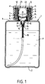
- la figure 1 est une vue en coupe d'un flacon doseur, conforme à l'invention, fermé par un capuchon vissé sur son goulot ;
- la figure 2 est une vue en coupe de la partie supérieure du flacon doseur de la figure 1, dont le capuchon est partiellement dévissé ;
- la figure 3 est une vue en coupe de la partie supérieure du flacon doseur des figures 1 et 2, dont la chambre de dosage est remplie et auquel on a retiré son capuchon.
- En se référant au dessin, on voit que le flacon doseur comporte un récipient 1, qui est un cylindre creux de section droite circulaire ayant un fond 2 et un goulot 3 à son extrémité opposée. Les parois de ce goulot 3 coopèrent, par leur surface extérieure, avec un capuchon 4 venant se visser sur ledit goulot. Le goulot 3 comporte en son intérieur une chambre de dosage 5 dans laquelle sont aspirées, comme cela sera décrit plus loin, des quantités dosées du produit liquide P contenu dans le récipient 1, ces doses étant distribuées hors du récipient 1. Le goulot 3 est un manchon cylindrique tubulaire, de section droite circulaire, prolongeant, sur l'axe du récipient 1, un orifice circulaire dont est munie la paroi 6 dudit récipient 1, en regard du fond 2. Ce goulot 3 comporte, de plus, sur sa sur face extérieure, un filetage 7 qui coopère avec un filetage intérieur 8 du capuchon 4. Le capuchon 4 est cylindrique ; il a une extrémité ouverte et une extrémité obturée par un fond ; son diamètre intérieur est légèrement supérieur au diamètre extérieur du goulot 3.
- Le goulot 3 comporte en son intérieur une capsule 9 ayant un fond 10̸ et une paroi cylindrique épousant sensiblement la surface intérieure du goulot 3. Le fond 10̸ est positionné au niveau de la paroi 6 du récipient 1, parallèlement a celle-ci. L'extrémité de la capsule 9 opposée à ce fond 10̸ est une ouverture libre, qui est terminée par une collerette annulaire 11, en saillie vers l'extérieur du goulot 3. Ladite collerette 11 s'appuie sur l'extrémité libre du goulot 3. Le fond du capuchon 4 est muni sur sa surface en regard du goulot 3 d'une protubérance annulaire 12, qui vient s'appuyer sur la collerette 11 lorsque le capuchon 4 est vissé. Le fond 10̸ de la capsule 9 est muni en son intérieur, sur sa surface destinée a être en regard du capuchon 4, d'une jupe annulaire 13 centrée sur l'axe du récipient 1. Ce fond 10̸ est, de plus, prolongé par un canal 14 s'étendant vers l'intérieur du réservoir 1, ce canal 14 ayant le même axe que le récipient 1, son intersection avec le plan du fond 10̸ ayant un diamètre inférieur au diamètre intérieur de la jupe 13.
- Sur la surface extérieure de la jupe 13, vient se positionner un organe en soufflet 15. Cet organe en soufflet 15 délimite, avec le fond 10̸ et le canal 14 la chambre de dosage 5 du flacon doseur. Il a une configuration en accordéon, dont les saillies intérieures sont positionnées, sensiblement, selon un cylindre dont le diamètre est le diamètre extérieur de la jupe 13, et dont les saillies extérieures sont disposées sur un cylindre proche de la surface intérieure de la paroi de la capsule 9. Le fond de la chambre 5 est ouvert vers l'intérieur du récipient 1 par l'intermédiaire d'une ouverture 16 qui termine le canal 14. Ce canal 14 s'évase sensiblement de ladite ouverture 16 vers le plan du fond 10̸. Cette ouverture 16 est elle-même prolongée axialement, vers l'intérieur du réservoir 1, par un conduit 17 dans lequel est emboîté, avec un léger serrage, un tube plongeur 18 plongeant dans le liquide P du réservoir 1, son extrémité étant proche du fond 2 du réservoir 1. Le canal 14 comporte en son intérieur une bille sphérique 19, dont le diamètre est supérieur à celui de l'ouverture 16. Lorsqu'il n'est exercé, sur cette bille 19, aucune action pouvant la repousser vers l'intérieur de la chambre 5, elle tombe au fond du canal 14 et vient boucher l'ouverture 16. Le canal 14 comporte, de plus, un micro-trou 20̸, qui traverse sa paroi. Ce micro-trou 20̸ est positionné suffisamment loin de l'ouverture 16 de façon à ne pas être obturé par les parois de la bille 19, lorsque celle-ci ferme l'ouverture 16.
- Sur le capuchon 4 est monté axialement un organe poussoir 21 ayant une extrémité sphéroïdale destinée à s'appuyer, lorsque le capuchon 4 est en position sur le goulot 3, sur l'extrémité libre du soufflet 15 opposée au fond de la chambre 5. La partie de cet organe poussoir 21, opposée à sa partie sphéroïdale, est un manchon 22 qui coopère avec un manchon intérieur 23, dont est muni axialement le capuchon 4, le manchon 22 étant emboîté sur la surface extérieure du manchon 23, avec un léger serrage. La longueur de ce manchon 22 est telle que, lorsque le capuchon 4 est vissé en position fermée sur le goulot 3, l'organe poussoir 21 appuie et maintient le soufflet 15 dans une position comprimée.
- Les différentes pièces de ce flacon doseur sont moulées en matière plastique. Son montage est relativement simple : une fois le réservoir rempli de produit P, après avoir assemblé le soufflet 15 et la capsule 9, par l'intermédiaire de la jupe 13, ainsi que le tube plongeur 18 et le canal 14, grâce au conduit 17, on place la bille 19 dans le canal 14, on déforme les bords de l'ouverture du canal 14 dans le fond 10̸ pour empêcher la bille 19 de ressortir, puis on insère la capsule 9 à l'intérieur du goulot 3, la collerette 11 venant s'appuyer sur l'extrémité libre de ce goulot 3. Il reste alors à visser le capuchon 4 sur le goulot 3.
- Pour utiliser un tel flacon doseur, dont le réservoir 1 est, au moins partiellement, rempli par un liquide P, et, sur lequel le capuchon 4 est vissé en position fermée sur le goulot 3, on dévisse ledit capuchon 4, ce qui a pour effet de le faire remonter axialement le long du goulot 3. La montée progressive de l'organe poussoir 21 dans la capsule 9 permet au soufflet 15, jusque là maintenu en compression, de se déployer élastiquement jusqu'à une position totalement dépliée, lorsque l'organe poussoir 21 n'est plus en contact avec l'extrémité libre de la chambre 5, extrémité qui est celle du soufflet 15. L'organe poussoir 21 étant positionné de façon étanche sur l'extrémité libre du soufflet 15, l'augmentation du volume de la chambre 5 crée une différence de pression entre l'intérieur de ladite chambre 5 et l'intérieur du réservoir 1. Cette dépression soulève la bille 19 et aspire le liquide P du réservoir 1 ; le liquide passe progressivement, par l'intermédiaire du tube 18 et de l'ouverture 16, dans la chambre 5, afin d'équilibrer les pressions qui règnent dans le réservoir 1 et dans la chambre 5. La montée du liquide P dans la chambre 5 s'effectue tant que l'organe poussoir 21, déplacé vers le haut avec le capuchon 4, assure l'étanchéité en tête du soufflet 15. Quand cette étanchéité est rompue à l'enlèvement du capuchon 4, le liquide P tend à redescendre dans le récipient 1 mais alors, la bille 19 retombe dans le fond du canal 14 bouchant l'ouverture 16 et empêchant le liquide P de redescendre. L'utilisateur a ainsi, à sa disposition, une dose de produit d'un volume, qui est sensiblement celui de la chambre 5 lorsque celle-ci est déployée. Une fois que le liquide P contenu dans la chambre 5 a été versé, on revisse le capuchon 4 sur le goulot 3. L'organe poussoir 21 vient à nouveau s'appuyer sur les bords de l'ouverture libre de la chambre 5, par l'intermédiaire de sa surface sphéroïdale et le soufflet 15 est replié en position comprimée. En repliant la chambre 5, l'organe poussoir 21, en appui étanche sur l'extrémité libre du soufflet 15, comprime l'air de la chambre 5 ; cet air ne pouvant s'échapper par l'ouverture 16 bouchée par la bille 19, est refoulé par le micro-trou 20̸. Le volume d'air ainsi chassé passe dans le réservoir 1 et comble la dépression, qui pouvait exister dans le réservoir 1, par rapport à la chambre de dosage 5, en apportant un volume d'air sensiblement équivalent au volume de liquide P, qui a été versé.
Claims (10)
- Flacon doseur comportant d'une part un récipient (1) destiné à contenir un produit liquide (P), ledit récipient (1) étant surmonté par un goulot (3) et d'autre part, une chambre de dosage (5) communiquant avec le récipient (1), caractérisé par le fait que le volume de ladite chambre (5) est variable, les parois latérales de la chambre (5) étant constituées par un soufflet (15), le fond (10̸, 14) de ladite chambre (5) comportant une ouverture (16) reliée à un tube plongeur (18) disposé dans le récipient (1), ladite ouverture (16) étant munie d'un clapet anti-retour (19) pouvant s'ouvrir vers l'intérieur de la chambre (5) sous l'effet d'une pression s'exerçant de l'intérieur du récipient (1) vers ladite chambre (5), l'extrémité de la chambre (5) opposée audit fond (10̸, 14) étant ouverte et associée à un organe obturateur (21) destiné à l'obturer de façon sensiblement étanche lorsque l'on passe d'une position repliée de la chambre (5) à une position dépliée, ladite extrémité aboutissant en position dépliée de la chambre (5) à l'intérieur du goulot (3), l'ensemble comportant au moins un passage (20̸) permettant l'évacuation de l'air de la chambre (5) lorsqu'on replie celle-ci.
- Flacon doseur selon la revendication 1, caractérisé par le fait que le soufflet (15), que forment les parois latérales de la chambre (5), est un organe élastique, qui se déploie lorsqu'il n'est l'objet d'aucune contrainte en compression selon son axe, le goulot (3) étant associé à un capuchon (4), qui est muni d'un organe poussoir (21) destiné à s'enfiler à l'intérieur du goulot (3) et à s'appuyer sur l'extrémité ouverte dudit soufflet (15), pour maintenir ledit soufflet (15), en compression, dans sa position repliée.
- Flacon doseur selon la revendication 2, caractérisé par le fait que l'organe poussoir (21) du capuchon (4) est aussi l'organe obturateur (21) de l'extrémité ouverte du soufflet (15).
- Flacon doseur selon la revendication 3, caractérisé par le fait que la surface de l'organe poussoir (21) du côté de son appui sur l'extrémité ouverte du soufflet (15) est convexe et épouse sensiblement les bords de ladite extrémité.
- Flacon doseur selon l'une des revendications 2 à 4, caractérisé par le fait que le capuchon (4) et le goulot (3) sont munis de filetages complémentaires (7, 8) l'organe poussoir (21) étant, selon qu'on effectue un vissage ou un dévissage du capuchon (4) sur ledit goulot (3), soit mis en appui sur l'extrémité libre du soufflet (15), soit retiré de l'intérieur du goulot (3).
- Flacon doseur selon l'une des revendications 1 à 5, caractérisé par le fait que l'ouverture (16) du fond (10̸, 14) de la chambre (5) est une ouverture circulaire, le clapet anti-retour, qui lui est associé, comportant une bille (19), dont le diamètre est plus important que le diamètre de l'ouverture (16), bille (19), qui, en position d'obturation, vient coopérer avec les bords de ladite ouverture (16).
- Flacon doseur selon la revendication 6, caractérisé par le fait que l'ouverture (16) du fond (10̸, 14) de la chambre (5) est ménagée à une des extrémités d'un canal (14) dont les parois s'évasent de ladite ouverture (16) vers l'intérieur de la chambre (5), ledit canal (14) servant de guide pour la bille (19) lorsqu'elle se soulève ou retombe sur le fond pour ouvrir ou obturer ladite ouverture (16).
- Flacon doseur selon l'une des revendications 1 à 7, caractérisé par le fait que le fond (10̸, 14) de la chambre (5) est percé d'au moins un micro- trou (20̸) servant de passage d'évacuation de l'air.
- Flacon doseur selon l'une des revendications 1 à 8, caractérisé par le fait que le soufflet (15) est une pièce distincte du fond (10̸, 14) de la chambre (5), et est positionné sur celui-ci par l'intermédiaire d'une jupe (13) annulaire dont est muni ledit fond (10̸, 14) et sur laquelle vient s'emboîter avec un léger serrage l'extrémité du soufflet (15) opposée à son extrémité ouverte.
- Flacon doseur selon la revendication 9, caractérisé par le fait que le fond (10̸, 14) de la chambre (5) est le fond (10̸) d'une capsule (9) cylindrique qui est ouverte à son autre extrémité et dont la paroi épouse la surface extérieure du goulot (3), son extrémité ouverte étant munie d'une collerette (11) annulaire en saillie vers l'extérieur par rapport à ladite paroi, collerette (11) qui se positionne sur les bords du goulot (3).
Priority Applications (1)
| Application Number | Priority Date | Filing Date | Title |
|---|---|---|---|
| AT90400194T ATE88153T1 (de) | 1989-02-14 | 1990-01-23 | Flasche mit dosiervorrichtung. |
Applications Claiming Priority (2)
| Application Number | Priority Date | Filing Date | Title |
|---|---|---|---|
| FR8901905A FR2643045B1 (fr) | 1989-02-14 | 1989-02-14 | Flacon doseur |
| FR8901905 | 1989-02-14 |
Publications (2)
| Publication Number | Publication Date |
|---|---|
| EP0383644A1 EP0383644A1 (fr) | 1990-08-22 |
| EP0383644B1 true EP0383644B1 (fr) | 1993-04-14 |
Family
ID=9378773
Family Applications (1)
| Application Number | Title | Priority Date | Filing Date |
|---|---|---|---|
| EP90400194A Expired - Lifetime EP0383644B1 (fr) | 1989-02-14 | 1990-01-23 | Flacon doseur |
Country Status (7)
| Country | Link |
|---|---|
| US (1) | US5031802A (fr) |
| EP (1) | EP0383644B1 (fr) |
| AT (1) | ATE88153T1 (fr) |
| CA (1) | CA2009216A1 (fr) |
| DE (1) | DE69001308T2 (fr) |
| ES (1) | ES2040066T3 (fr) |
| FR (1) | FR2643045B1 (fr) |
Families Citing this family (29)
| Publication number | Priority date | Publication date | Assignee | Title |
|---|---|---|---|---|
| US5127553A (en) * | 1990-09-17 | 1992-07-07 | Primary Delivery Systems, Inc. | Metered liquid squeeze bottle |
| US5381930A (en) * | 1992-01-15 | 1995-01-17 | Kalabakas; Peter | Dispensing device for a measured volume of liquid |
| US5439178A (en) * | 1993-06-24 | 1995-08-08 | The Procter & Gamble Company | Pump device including multiple function collapsible pump chamber |
| US5388621A (en) * | 1993-10-05 | 1995-02-14 | Icee Ventures, Inc. | Pressurized transfer tank security system |
| US5664703A (en) * | 1994-02-28 | 1997-09-09 | The Procter & Gamble Company | Pump device with collapsible pump chamber having supply container venting system and integral shipping seal |
| US5518147A (en) * | 1994-03-01 | 1996-05-21 | The Procter & Gamble Company | Collapsible pump chamber having predetermined collapsing pattern |
| US5561901A (en) * | 1994-10-06 | 1996-10-08 | The Procter & Gamble Company | Assembly process including severing part of integral collapsible pump chamber |
| US5476195A (en) * | 1994-10-06 | 1995-12-19 | Procter & Gamble Company | Pump device with collapsible pump chamber and including dunnage means |
| DE19808040A1 (de) * | 1998-02-26 | 1999-09-09 | Dehn | Dosierbecher mit Verschluß |
| DE59905482D1 (de) | 1998-08-03 | 2003-06-12 | Createchnic Ag Nuerensdorf | Dosier- und messvorrichtung für fliessfähige medien |
| FR2799449B1 (fr) * | 1999-10-06 | 2001-12-14 | Oreal | Flacon doseur a pompe |
| US6675845B2 (en) * | 2001-06-05 | 2004-01-13 | The Procter & Gamble Company | Package and method for controlled metered dose dispensing of a fluid product |
| US7331489B2 (en) | 2004-11-19 | 2008-02-19 | Glynntech, Inc. | Metered dose squeeze dispenser having a dip tube with a rotatable leg |
| US7350673B2 (en) | 2004-11-19 | 2008-04-01 | Glynntech, Inc. | Metered dose squeeze dispenser |
| US7222755B2 (en) | 2004-11-19 | 2007-05-29 | Glynntech, Inc. | Metered dose squeeze dispenser with flexible-T dip tube |
| US7549816B2 (en) | 2004-11-19 | 2009-06-23 | Glynntech, Inc. | Metered dose squeeze dispenser with brush |
| CN102449558B (zh) * | 2009-03-30 | 2014-08-27 | 佳能株式会社 | 显影剂供应容器和显影剂供应系统 |
| CN103950627B (zh) * | 2014-04-02 | 2016-04-27 | 日照开富乐包装制品有限公司 | 一种陶瓷导流防伪瓶塞 |
| US10392239B2 (en) * | 2016-07-29 | 2019-08-27 | Berry Plastics Corporation | Liquid dispenser |
| EP3378569A1 (fr) | 2017-03-21 | 2018-09-26 | The Procter & Gamble Company | Dispositif de distribution |
| EP3450351A1 (fr) | 2017-09-01 | 2019-03-06 | The Procter & Gamble Company | Appareil et procédé pour distribuer une dose mesurée d'un produit |
| EP3489171B1 (fr) | 2017-11-23 | 2026-03-18 | The Procter & Gamble Company | Piston avec fermeture flexible pour conteneur d'aérosol |
| EP3513880B1 (fr) | 2018-01-23 | 2021-08-25 | The Procter & Gamble Company | Dispositif de distribution approprié pour un produit moussant |
| US10640279B2 (en) | 2018-08-01 | 2020-05-05 | Veritiv Operating Company | Container assembly with syringe |
| EP3874241B1 (fr) * | 2018-10-31 | 2024-05-29 | Dow Global Technologies LLC | Capuchon de dosage à volume réglable |
| US10850914B2 (en) | 2018-11-08 | 2020-12-01 | The Procter And Gamble Company | Dip tube aerosol dispenser with upright actuator |
| US11267644B2 (en) | 2018-11-08 | 2022-03-08 | The Procter And Gamble Company | Aerosol foam dispenser and methods for delivering a textured foam product |
| EP3663455B1 (fr) * | 2018-12-03 | 2022-06-01 | Aptar Radolfzell GmbH | Récipient doseur et ensembles dotés d'un récipient doseur |
| US11768095B2 (en) * | 2019-10-07 | 2023-09-26 | Ams, Llc | Measured fluid dispenser |
Family Cites Families (9)
| Publication number | Priority date | Publication date | Assignee | Title |
|---|---|---|---|---|
| US2311367A (en) * | 1940-04-22 | 1943-02-16 | Laura A Chambers | Liquid applicator |
| US2680477A (en) * | 1951-12-07 | 1954-06-08 | Jr Martin P Schira | Pump cap for fuel tanks |
| GB741427A (en) * | 1953-01-19 | 1955-12-07 | James Reynolds | Improvements in or relating to pourers for fluids |
| FR1333491A (fr) * | 1962-09-12 | 1963-07-26 | Appareil permettant le pompage par doses précises d'un liquide contenu dans une bouteille | |
| US3171446A (en) * | 1963-02-11 | 1965-03-02 | Delman Co | Fluid dispenser and container |
| DE2107074A1 (de) * | 1971-02-15 | 1972-11-09 | Stella Kg, Werner Deussen, 6229 Niederwalluf | Dosierender Behälterverschluß |
| IT1202615B (it) * | 1987-03-03 | 1989-02-09 | Guala Angelo Spa | Flacone per prodotti medicinali in generale e per sciroppi in particolare |
| FR2630712B1 (fr) * | 1988-04-27 | 1990-10-12 | Hoechst Behring Sapb | Recipient a dispositif distributeur pour produit liquide ou pateux |
| US4875603A (en) * | 1989-01-26 | 1989-10-24 | Primary Delivery Systems, Inc. | Metered dispensing cap for tubes |
-
1989
- 1989-02-14 FR FR8901905A patent/FR2643045B1/fr not_active Expired - Lifetime
-
1990
- 1990-01-23 DE DE90400194T patent/DE69001308T2/de not_active Expired - Fee Related
- 1990-01-23 ES ES199090400194T patent/ES2040066T3/es not_active Expired - Lifetime
- 1990-01-23 AT AT90400194T patent/ATE88153T1/de not_active IP Right Cessation
- 1990-01-23 EP EP90400194A patent/EP0383644B1/fr not_active Expired - Lifetime
- 1990-02-02 CA CA002009216A patent/CA2009216A1/fr not_active Abandoned
- 1990-02-13 US US07/479,245 patent/US5031802A/en not_active Expired - Fee Related
Also Published As
| Publication number | Publication date |
|---|---|
| DE69001308T2 (de) | 1993-11-25 |
| FR2643045A1 (fr) | 1990-08-17 |
| FR2643045B1 (fr) | 1991-06-07 |
| ES2040066T3 (es) | 1993-10-01 |
| US5031802A (en) | 1991-07-16 |
| EP0383644A1 (fr) | 1990-08-22 |
| DE69001308D1 (de) | 1993-05-19 |
| CA2009216A1 (fr) | 1990-08-14 |
| ATE88153T1 (de) | 1993-04-15 |
Similar Documents
| Publication | Publication Date | Title |
|---|---|---|
| EP0383644A1 (fr) | Flacon doseur | |
| EP0505299B1 (fr) | Dispositif doseur adaptable sur des contenants divers | |
| EP0757592B1 (fr) | Pompe a precompression perfectionnee | |
| WO1995025945A1 (fr) | Dispositif doseur destine a delivrer des doses unitaires constantes | |
| EP0995976A1 (fr) | Embout doseur et récipient équipé d'un embout doseur selon l'invention | |
| EP1572375B1 (fr) | Pompe doseuse a actionnement manuel | |
| WO2022123128A1 (fr) | Dispositif de distribution de doses de poudre | |
| FR2693174A1 (fr) | Perfectionnements aux dispositifs distributeur et doseur de produit. | |
| WO2014108637A1 (fr) | Distributeur de produit fluide | |
| FR2656900A1 (fr) | Pompe manuelle a precompression pour la pulverisation d'un liquide, notamment d'un parfum. | |
| FR2735004A1 (fr) | Dispositif pour delivrer du savon liquide a un generateur de mousse | |
| EP0312474B1 (fr) | Distributeur automatique de produits pâteux | |
| EP3417948B1 (fr) | Pompe moulée pour la distribution d'un produit fluidique | |
| EP0350376B1 (fr) | Valve doseuse pour aerosols | |
| EP0605275B1 (fr) | Ensemble pour la pulvérisation d'un liquide comportant une pompe à précompression | |
| EP0251863B1 (fr) | Ensemble doseur pour un produit pâteux ou semi-liquide | |
| FR2668456A1 (fr) | Distributeur doseur de produits alimentaires liquides ou pateux. | |
| FR2612571A1 (fr) | Distributeur a pompe pour petites doses precises de produit fluide | |
| FR2730219A1 (fr) | Doseur pour recipient sous pression a valve continue | |
| FR2799449A1 (fr) | Flacon doseur a pompe | |
| FR2672957A1 (fr) | Pompe ou valve manuelle comportant un tube ou une tige coulissant dans son conduit d'admission. | |
| FR2894633A1 (fr) | Pompe a chemise coulissante | |
| FR2647423A2 (fr) | Recipient ou flacon aseptique conservateur d'un produit non pateux | |
| FR2777867A1 (fr) | Ensemble pour le conditionnement et l'application dosee d'un produit fluide | |
| FR2767073A1 (fr) | Tete de distribution de liquide et conditionnement de fluide la comportant |
Legal Events
| Date | Code | Title | Description |
|---|---|---|---|
| PUAI | Public reference made under article 153(3) epc to a published international application that has entered the european phase |
Free format text: ORIGINAL CODE: 0009012 |
|
| 17P | Request for examination filed |
Effective date: 19900124 |
|
| AK | Designated contracting states |
Kind code of ref document: A1 Designated state(s): AT BE CH DE ES FR GB IT LI NL SE |
|
| 17Q | First examination report despatched |
Effective date: 19920910 |
|
| GRAA | (expected) grant |
Free format text: ORIGINAL CODE: 0009210 |
|
| AK | Designated contracting states |
Kind code of ref document: B1 Designated state(s): AT BE CH DE ES FR GB IT LI NL SE |
|
| PG25 | Lapsed in a contracting state [announced via postgrant information from national office to epo] |
Ref country code: SE Effective date: 19930414 Ref country code: NL Effective date: 19930414 Ref country code: AT Effective date: 19930414 |
|
| REF | Corresponds to: |
Ref document number: 88153 Country of ref document: AT Date of ref document: 19930415 Kind code of ref document: T |
|
| ITF | It: translation for a ep patent filed | ||
| REF | Corresponds to: |
Ref document number: 69001308 Country of ref document: DE Date of ref document: 19930519 |
|
| GBT | Gb: translation of ep patent filed (gb section 77(6)(a)/1977) |
Effective date: 19930429 |
|
| NLV1 | Nl: lapsed or annulled due to failure to fulfill the requirements of art. 29p and 29m of the patents act | ||
| REG | Reference to a national code |
Ref country code: ES Ref legal event code: FG2A Ref document number: 2040066 Country of ref document: ES Kind code of ref document: T3 |
|
| PG25 | Lapsed in a contracting state [announced via postgrant information from national office to epo] |
Ref country code: LI Effective date: 19940131 Ref country code: CH Effective date: 19940131 Ref country code: BE Effective date: 19940131 |
|
| PLBE | No opposition filed within time limit |
Free format text: ORIGINAL CODE: 0009261 |
|
| STAA | Information on the status of an ep patent application or granted ep patent |
Free format text: STATUS: NO OPPOSITION FILED WITHIN TIME LIMIT |
|
| 26N | No opposition filed | ||
| BERE | Be: lapsed |
Owner name: L' OREAL Effective date: 19940131 |
|
| REG | Reference to a national code |
Ref country code: CH Ref legal event code: PL |
|
| PGFP | Annual fee paid to national office [announced via postgrant information from national office to epo] |
Ref country code: DE Payment date: 19991231 Year of fee payment: 11 |
|
| PGFP | Annual fee paid to national office [announced via postgrant information from national office to epo] |
Ref country code: FR Payment date: 20000112 Year of fee payment: 11 |
|
| PGFP | Annual fee paid to national office [announced via postgrant information from national office to epo] |
Ref country code: GB Payment date: 20000119 Year of fee payment: 11 |
|
| PGFP | Annual fee paid to national office [announced via postgrant information from national office to epo] |
Ref country code: ES Payment date: 20000131 Year of fee payment: 11 |
|
| PG25 | Lapsed in a contracting state [announced via postgrant information from national office to epo] |
Ref country code: GB Free format text: LAPSE BECAUSE OF NON-PAYMENT OF DUE FEES Effective date: 20010123 |
|
| PG25 | Lapsed in a contracting state [announced via postgrant information from national office to epo] |
Ref country code: ES Free format text: LAPSE BECAUSE OF NON-PAYMENT OF DUE FEES Effective date: 20010124 |
|
| GBPC | Gb: european patent ceased through non-payment of renewal fee |
Effective date: 20010123 |
|
| PG25 | Lapsed in a contracting state [announced via postgrant information from national office to epo] |
Ref country code: FR Free format text: LAPSE BECAUSE OF NON-PAYMENT OF DUE FEES Effective date: 20010928 |
|
| PG25 | Lapsed in a contracting state [announced via postgrant information from national office to epo] |
Ref country code: DE Free format text: LAPSE BECAUSE OF NON-PAYMENT OF DUE FEES Effective date: 20011101 |
|
| REG | Reference to a national code |
Ref country code: FR Ref legal event code: ST |
|
| REG | Reference to a national code |
Ref country code: ES Ref legal event code: FD2A Effective date: 20020916 |
|
| PG25 | Lapsed in a contracting state [announced via postgrant information from national office to epo] |
Ref country code: IT Free format text: LAPSE BECAUSE OF NON-PAYMENT OF DUE FEES;WARNING: LAPSES OF ITALIAN PATENTS WITH EFFECTIVE DATE BEFORE 2007 MAY HAVE OCCURRED AT ANY TIME BEFORE 2007. THE CORRECT EFFECTIVE DATE MAY BE DIFFERENT FROM THE ONE RECORDED. Effective date: 20050123 |