EP0383733A1 - Apparatus for regulating the air and gas flow to an internal combustion engine - Google Patents
Apparatus for regulating the air and gas flow to an internal combustion engine Download PDFInfo
- Publication number
- EP0383733A1 EP0383733A1 EP90830054A EP90830054A EP0383733A1 EP 0383733 A1 EP0383733 A1 EP 0383733A1 EP 90830054 A EP90830054 A EP 90830054A EP 90830054 A EP90830054 A EP 90830054A EP 0383733 A1 EP0383733 A1 EP 0383733A1
- Authority
- EP
- European Patent Office
- Prior art keywords
- gas
- engine
- restrictor member
- duct
- running
- Prior art date
- Legal status (The legal status is an assumption and is not a legal conclusion. Google has not performed a legal analysis and makes no representation as to the accuracy of the status listed.)
- Withdrawn
Links
Images
Classifications
-
- F—MECHANICAL ENGINEERING; LIGHTING; HEATING; WEAPONS; BLASTING
- F02—COMBUSTION ENGINES; HOT-GAS OR COMBUSTION-PRODUCT ENGINE PLANTS
- F02D—CONTROLLING COMBUSTION ENGINES
- F02D19/00—Controlling engines characterised by their use of non-liquid fuels, pluralities of fuels, or non-fuel substances added to the combustible mixtures
- F02D19/06—Controlling engines characterised by their use of non-liquid fuels, pluralities of fuels, or non-fuel substances added to the combustible mixtures peculiar to engines working with pluralities of fuels, e.g. alternatively with light and heavy fuel oil, other than engines indifferent to the fuel consumed
- F02D19/0663—Details on the fuel supply system, e.g. tanks, valves, pipes, pumps, rails, injectors or mixers
- F02D19/0673—Valves; Pressure or flow regulators; Mixers
- F02D19/0678—Pressure or flow regulators therefor; Fuel metering valves therefor
-
- F—MECHANICAL ENGINEERING; LIGHTING; HEATING; WEAPONS; BLASTING
- F02—COMBUSTION ENGINES; HOT-GAS OR COMBUSTION-PRODUCT ENGINE PLANTS
- F02D—CONTROLLING COMBUSTION ENGINES
- F02D19/00—Controlling engines characterised by their use of non-liquid fuels, pluralities of fuels, or non-fuel substances added to the combustible mixtures
- F02D19/06—Controlling engines characterised by their use of non-liquid fuels, pluralities of fuels, or non-fuel substances added to the combustible mixtures peculiar to engines working with pluralities of fuels, e.g. alternatively with light and heavy fuel oil, other than engines indifferent to the fuel consumed
- F02D19/0663—Details on the fuel supply system, e.g. tanks, valves, pipes, pumps, rails, injectors or mixers
- F02D19/0673—Valves; Pressure or flow regulators; Mixers
- F02D19/0676—Multi-way valves; Switch-over valves
-
- F—MECHANICAL ENGINEERING; LIGHTING; HEATING; WEAPONS; BLASTING
- F02—COMBUSTION ENGINES; HOT-GAS OR COMBUSTION-PRODUCT ENGINE PLANTS
- F02M—SUPPLYING COMBUSTION ENGINES IN GENERAL WITH COMBUSTIBLE MIXTURES OR CONSTITUENTS THEREOF
- F02M13/00—Arrangements of two or more separate carburettors; Carburettors using more than one fuel
- F02M13/08—Carburettors adapted to use liquid and gaseous fuels, e.g. alternatively
-
- F—MECHANICAL ENGINEERING; LIGHTING; HEATING; WEAPONS; BLASTING
- F02—COMBUSTION ENGINES; HOT-GAS OR COMBUSTION-PRODUCT ENGINE PLANTS
- F02M—SUPPLYING COMBUSTION ENGINES IN GENERAL WITH COMBUSTIBLE MIXTURES OR CONSTITUENTS THEREOF
- F02M21/00—Apparatus for supplying engines with non-liquid fuels, e.g. gaseous fuels stored in liquid form
- F02M21/02—Apparatus for supplying engines with non-liquid fuels, e.g. gaseous fuels stored in liquid form for gaseous fuels
- F02M21/0218—Details on the gaseous fuel supply system, e.g. tanks, valves, pipes, pumps, rails, injectors or mixers
- F02M21/023—Valves; Pressure or flow regulators in the fuel supply or return system
- F02M21/0239—Pressure or flow regulators therefor
-
- F—MECHANICAL ENGINEERING; LIGHTING; HEATING; WEAPONS; BLASTING
- F02—COMBUSTION ENGINES; HOT-GAS OR COMBUSTION-PRODUCT ENGINE PLANTS
- F02D—CONTROLLING COMBUSTION ENGINES
- F02D19/00—Controlling engines characterised by their use of non-liquid fuels, pluralities of fuels, or non-fuel substances added to the combustible mixtures
- F02D19/06—Controlling engines characterised by their use of non-liquid fuels, pluralities of fuels, or non-fuel substances added to the combustible mixtures peculiar to engines working with pluralities of fuels, e.g. alternatively with light and heavy fuel oil, other than engines indifferent to the fuel consumed
- F02D19/0639—Controlling engines characterised by their use of non-liquid fuels, pluralities of fuels, or non-fuel substances added to the combustible mixtures peculiar to engines working with pluralities of fuels, e.g. alternatively with light and heavy fuel oil, other than engines indifferent to the fuel consumed characterised by the type of fuels
- F02D19/0642—Controlling engines characterised by their use of non-liquid fuels, pluralities of fuels, or non-fuel substances added to the combustible mixtures peculiar to engines working with pluralities of fuels, e.g. alternatively with light and heavy fuel oil, other than engines indifferent to the fuel consumed characterised by the type of fuels at least one fuel being gaseous, the other fuels being gaseous or liquid at standard conditions
-
- Y—GENERAL TAGGING OF NEW TECHNOLOGICAL DEVELOPMENTS; GENERAL TAGGING OF CROSS-SECTIONAL TECHNOLOGIES SPANNING OVER SEVERAL SECTIONS OF THE IPC; TECHNICAL SUBJECTS COVERED BY FORMER USPC CROSS-REFERENCE ART COLLECTIONS [XRACs] AND DIGESTS
- Y02—TECHNOLOGIES OR APPLICATIONS FOR MITIGATION OR ADAPTATION AGAINST CLIMATE CHANGE
- Y02T—CLIMATE CHANGE MITIGATION TECHNOLOGIES RELATED TO TRANSPORTATION
- Y02T10/00—Road transport of goods or passengers
- Y02T10/10—Internal combustion engine [ICE] based vehicles
- Y02T10/30—Use of alternative fuels, e.g. biofuels
Definitions
- the invention relates to an apparatus for the controlled reduction of the flowrate of combustion air and gaseous fuel to an internal combustion engine which can be supplied with gas and gasoline (petrol) in a promiscuous (alternative) manner, comprising a restriction member able to take up a fixed position of maximum opening during the petrol-operated running of the engine to which said apparatus is associated, and a position varying according to the vacuum degree generated by the engine during the gas-operated running of the engine to which said apparatus is associated.
- a restriction member able to take up a fixed position of maximum opening during the petrol-operated running of the engine to which said apparatus is associated, and a position varying according to the vacuum degree generated by the engine during the gas-operated running of the engine to which said apparatus is associated.
- Known apparatuses of this type allow a correct operation of the engine when using a promiscuous (alternative) supply of gas or gasoline.
- the apparatus is mounted on the air-intake conduit upstream of the air filter.
- said restrictor member is fully open, and the apparatus has no influence on the engine operation.
- the restrictor member takes up one of the many possible positions between a position of maximum opening and a position of minimum opening (defined by a stop element), said two positions corresponding to the maximum and minimum revolution-per-minute running of the engine.
- the position of the restrictor member is determined by the vacuum generated by the engine in the combustion air-intake conduit.
- More or less complex kinematic systems connect the above mentioned restrictor member to shutter means of the gas supplying conduit, so that the cross-section of said conduit is made to vary according to the vacuum generated by the engine within the air intake conduit, thereby maintaining an optimal air/gas ratio all the time, with a consequent consumption reduction.
- the known apparatuses of this type are particularly complex and difficult to calibrate, owing to the complexity of the kinematic connecting mechanisms between the restrictor member of the combustion air conduit and the shutter means of the gaseous fuel supplying duct.
- the calibration - which is carried out by adjusting the position of minimum opening of said restrictor member in the air conduit, the minimum cross-section of the gaseous fuel supplying duct, and the elastic force to be exerted on said restrictor member by suitable counteracting elastic means - is made critical by the complexity of the apparatuses presently known and is, on the other hand, particularly delicate and crucial for an economical running of the engine. As the same apparatus can be mounted on engines which are very different both in capacity and power, the calibration is an indispensable operation to allow the same apparatus to meet the characteristics of the engine on which it is mounted each time.
- the object of the invention is to provide an apparatus of the above mentioned type, which is particularly simple and reliable and easily adjustable.
- the apparatus according to the invention is characterized, in practice, in that the restrictor member is a member rotatively supported by a pivot pin, which carries further means for adjusting the through section of the duct for the supply of gas to the engine, said further means rotating about the same axis of said restrictor member.
- the vacuum generated by the engine within the air intake conduit causes the restrictor member and directly, through the supporting pin of the latter, also the means for the adjustment of the flow section of the gas supply duct, to open more or less.
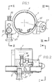
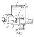
- the apparatus comprises a hollow cylindrical body 1 inside which a restrictor member is disposed having the form of a throttle valve 3 borne by an off-center pin or small shaft 3, which valve is able to increase or reduce the internal cross-section of the hollow cylindrical body 1, through which the combustion air sucked by the engine is made to flow.
- the body 1 may be fitted at the inlet of the sleeve of the air-filtering group or within the hoses of the injection engines.
- the pin 5 has a rotating valve 7 at one end thereof, capable of varying the internal cross-section of a duct 9 through which the gaseous fuel coming from a suitable tank is made to flow via a pressure reducer.
- the valve 7 may be formed by a flat of the pin or small shaft 5.
- Associated to the pin 5 are elastic return means formed, in the example shown, with a spiral spring 11 which urges the valve 7 and the restrictor member 3 in the closed position.
- the torque exerted by the spiral spring 11 on the pin 5 can be adjusted by a set screw 13 to which one of the end of the same spring is anchored or made to rest, the other end being anchored to the pin 5.
- An adjustable stop element for the throttle valve 3 is provided within the hollow body 1; said stop element, in the example of the drawing, is formed by the stem 15 of a solenoid valve 17 utilized for the purposes indicated below.
- the position of the adjustable stop element determines the minimum opening of the passage formed in the cylindrical hollow body 1.
- the stop is adjustable through a set means located on the solenoid valve 17. It is also possible to provide an adjustable stop located in another suitable position on the cylindrical hollow body 1.
- the maximum gas flowrate can be adjusted, according to the characteristics of the engine on which the apparatus is mounted, by acting on a screw 21 inserted in the duct 9 by means of which screw the maximum gas flow section is varied.
- the solenoid valve 17 When the engine is run by petrol supply, the solenoid valve 17 is activated to keep the throttle valve 3 in its opening position, while the gas supply is blocked upstream of the illustrated apparatus, for example in correspondence of the pressure reducer disposed between the valve 7 and the gas tank. In this condition, the apparatus according to the invention has no effect over the engine supply.
- the apparatus according to the invention is of simple design and can be very easily calibrated to fit all the various types of engines, the calibration being performed by acting on screws 13, 19 and 21.
Landscapes
- Engineering & Computer Science (AREA)
- Chemical & Material Sciences (AREA)
- Combustion & Propulsion (AREA)
- Mechanical Engineering (AREA)
- General Engineering & Computer Science (AREA)
- Oil, Petroleum & Natural Gas (AREA)
- Chemical Kinetics & Catalysis (AREA)
- General Chemical & Material Sciences (AREA)
- Output Control And Ontrol Of Special Type Engine (AREA)
Applications Claiming Priority (2)
| Application Number | Priority Date | Filing Date | Title |
|---|---|---|---|
| IT8909337A IT1233148B (it) | 1989-02-14 | 1989-02-14 | Dispositivo per la regolazione del flusso di aria e di gas ad un motore a combustione interna |
| IT933789 | 1989-02-14 |
Publications (1)
| Publication Number | Publication Date |
|---|---|
| EP0383733A1 true EP0383733A1 (en) | 1990-08-22 |
Family
ID=11128639
Family Applications (1)
| Application Number | Title | Priority Date | Filing Date |
|---|---|---|---|
| EP90830054A Withdrawn EP0383733A1 (en) | 1989-02-14 | 1990-02-13 | Apparatus for regulating the air and gas flow to an internal combustion engine |
Country Status (2)
| Country | Link |
|---|---|
| EP (1) | EP0383733A1 (it) |
| IT (1) | IT1233148B (it) |
Citations (9)
| Publication number | Priority date | Publication date | Assignee | Title |
|---|---|---|---|---|
| FR652764A (fr) * | 1927-09-23 | 1929-03-13 | Carburateur mélangeur pour moteurs a combustion interne alimentés par gazogène | |
| US1932370A (en) * | 1930-10-03 | 1933-10-24 | Star Drilling Machine Company | Gas valve construction |
| FR51235E (fr) * | 1940-11-20 | 1941-12-20 | Carburateur destiné à l'alimentation des moteurs à explosion au moyen d'un mélange pulvérisé de gaz acétylène dissous, d'huile, d'eau et d'air | |
| GB634330A (en) * | 1946-08-14 | 1950-03-15 | American Bosch Corp | Improvements in and relating to means for controlling the fuel and air supply to internal combustion devices |
| US2957759A (en) * | 1957-01-17 | 1960-10-25 | Bendix Corp | Gaseous fuel carburetor |
| CH579216A5 (en) * | 1974-03-12 | 1976-08-31 | Bonvin Charly | Gas or liq fuel metering device for IC engine - has flanged piston in bell space and carrying conical valve |
| US4096838A (en) * | 1975-12-26 | 1978-06-27 | Nippon Soken, Inc. | Fuel control system for an internal combustion engine |
| NL7706500A (en) * | 1977-06-13 | 1978-12-15 | Agas Nederland B V | Gas pressure auxiliary regulator - has throttle with valved by=pass causing excess pressure at very low consumption rate |
| GB2057056A (en) * | 1979-08-24 | 1981-03-25 | Bosch Gmbh Robert | Controlling the fuel-air mixture supply to an internal combustion engine |
-
1989
- 1989-02-14 IT IT8909337A patent/IT1233148B/it active
-
1990
- 1990-02-13 EP EP90830054A patent/EP0383733A1/en not_active Withdrawn
Patent Citations (9)
| Publication number | Priority date | Publication date | Assignee | Title |
|---|---|---|---|---|
| FR652764A (fr) * | 1927-09-23 | 1929-03-13 | Carburateur mélangeur pour moteurs a combustion interne alimentés par gazogène | |
| US1932370A (en) * | 1930-10-03 | 1933-10-24 | Star Drilling Machine Company | Gas valve construction |
| FR51235E (fr) * | 1940-11-20 | 1941-12-20 | Carburateur destiné à l'alimentation des moteurs à explosion au moyen d'un mélange pulvérisé de gaz acétylène dissous, d'huile, d'eau et d'air | |
| GB634330A (en) * | 1946-08-14 | 1950-03-15 | American Bosch Corp | Improvements in and relating to means for controlling the fuel and air supply to internal combustion devices |
| US2957759A (en) * | 1957-01-17 | 1960-10-25 | Bendix Corp | Gaseous fuel carburetor |
| CH579216A5 (en) * | 1974-03-12 | 1976-08-31 | Bonvin Charly | Gas or liq fuel metering device for IC engine - has flanged piston in bell space and carrying conical valve |
| US4096838A (en) * | 1975-12-26 | 1978-06-27 | Nippon Soken, Inc. | Fuel control system for an internal combustion engine |
| NL7706500A (en) * | 1977-06-13 | 1978-12-15 | Agas Nederland B V | Gas pressure auxiliary regulator - has throttle with valved by=pass causing excess pressure at very low consumption rate |
| GB2057056A (en) * | 1979-08-24 | 1981-03-25 | Bosch Gmbh Robert | Controlling the fuel-air mixture supply to an internal combustion engine |
Also Published As
| Publication number | Publication date |
|---|---|
| IT1233148B (it) | 1992-03-14 |
| IT8909337A0 (it) | 1989-02-14 |
Similar Documents
| Publication | Publication Date | Title |
|---|---|---|
| US5377646A (en) | Liquid petroleum gas fuel delivery systems | |
| EP0563223B1 (en) | Device for injecting a gaseous fuel into an internal combustion engine | |
| US4453523A (en) | Pressure balanced flow regulator for gaseous fuel engine | |
| US20020025257A1 (en) | Fuel metering unit | |
| JP2000097130A (ja) | 燃料噴射式エンジン用の燃料及び空気送給装置 | |
| KR920006544B1 (ko) | 압축 착화엔진의 벤츄리장치 및 이것을 이용한 무화(fumigation)시스템 | |
| JPH05263720A (ja) | 揮発性燃料成分供給装置 | |
| JPS6134337A (ja) | 自己着座作用を有するニードル弁を備えた気化器 | |
| US5002705A (en) | Carburetor including an idling adjustment system | |
| US5441673A (en) | Carburetor for an internal combustion engine | |
| WO1982000046A1 (en) | Lpg supply system | |
| CA1046366A (en) | Control apparatus for diesel engine | |
| EP0383733A1 (en) | Apparatus for regulating the air and gas flow to an internal combustion engine | |
| US4450821A (en) | Gaseous fuel delivery system | |
| US4475521A (en) | Fuel injection pump for internal combustion engines | |
| EP0287366B1 (en) | Carburetor and valve mechanism | |
| US4524034A (en) | Carburetor | |
| US4931226A (en) | Charge forming apparatus | |
| US4853160A (en) | Apparatus for adjusting a variable length valve member for a needle valve | |
| US4110416A (en) | Sonic throttle for automobile | |
| US4572809A (en) | Carburettor | |
| US3026095A (en) | Carburetor construction | |
| SU1138050A3 (ru) | Карбюратор с посто нным разрежением и его варианты | |
| US3859974A (en) | Cold starting devices for internal combustion engines | |
| GB2131876A (en) | Carburettor throttle valves |
Legal Events
| Date | Code | Title | Description |
|---|---|---|---|
| PUAI | Public reference made under article 153(3) epc to a published international application that has entered the european phase |
Free format text: ORIGINAL CODE: 0009012 |
|
| AK | Designated contracting states |
Kind code of ref document: A1 Designated state(s): ES FR GR NL |
|
| 17P | Request for examination filed |
Effective date: 19910119 |
|
| 17Q | First examination report despatched |
Effective date: 19910729 |
|
| STAA | Information on the status of an ep patent application or granted ep patent |
Free format text: STATUS: THE APPLICATION IS DEEMED TO BE WITHDRAWN |
|
| 18D | Application deemed to be withdrawn |
Effective date: 19911210 |