EP0384068A1 - Dispositif de déclanchement automatique pour atomiseur - Google Patents
Dispositif de déclanchement automatique pour atomiseur Download PDFInfo
- Publication number
- EP0384068A1 EP0384068A1 EP89310752A EP89310752A EP0384068A1 EP 0384068 A1 EP0384068 A1 EP 0384068A1 EP 89310752 A EP89310752 A EP 89310752A EP 89310752 A EP89310752 A EP 89310752A EP 0384068 A1 EP0384068 A1 EP 0384068A1
- Authority
- EP
- European Patent Office
- Prior art keywords
- post
- activator
- fusible element
- lever
- sprinkler head
- Prior art date
- Legal status (The legal status is an assumption and is not a legal conclusion. Google has not performed a legal analysis and makes no representation as to the accuracy of the status listed.)
- Withdrawn
Links
- 239000012190 activator Substances 0.000 title claims abstract description 25
- 239000012530 fluid Substances 0.000 claims abstract description 3
- 238000006073 displacement reaction Methods 0.000 claims abstract 2
- 229910000679 solder Inorganic materials 0.000 claims description 9
- 230000000694 effects Effects 0.000 claims description 4
- 230000008602 contraction Effects 0.000 claims description 3
- 238000009413 insulation Methods 0.000 claims 1
- 230000000717 retained effect Effects 0.000 claims 1
- XLYOFNOQVPJJNP-UHFFFAOYSA-N water Substances O XLYOFNOQVPJJNP-UHFFFAOYSA-N 0.000 description 11
- 238000010276 construction Methods 0.000 description 6
- 239000007921 spray Substances 0.000 description 3
- 239000011521 glass Substances 0.000 description 2
- 230000002093 peripheral effect Effects 0.000 description 2
- 230000002159 abnormal effect Effects 0.000 description 1
- 230000003213 activating effect Effects 0.000 description 1
- 230000004913 activation Effects 0.000 description 1
- 230000000712 assembly Effects 0.000 description 1
- 238000000429 assembly Methods 0.000 description 1
- 230000006835 compression Effects 0.000 description 1
- 238000007906 compression Methods 0.000 description 1
- 230000005496 eutectics Effects 0.000 description 1
- 239000011810 insulating material Substances 0.000 description 1
- 239000012212 insulator Substances 0.000 description 1
- 239000007788 liquid Substances 0.000 description 1
- 239000000155 melt Substances 0.000 description 1
- 238000012986 modification Methods 0.000 description 1
- 230000004048 modification Effects 0.000 description 1
- 238000012856 packing Methods 0.000 description 1
Images

Classifications
-
- A—HUMAN NECESSITIES
- A62—LIFE-SAVING; FIRE-FIGHTING
- A62C—FIRE-FIGHTING
- A62C37/00—Control of fire-fighting equipment
- A62C37/08—Control of fire-fighting equipment comprising an outlet device containing a sensor, or itself being the sensor, i.e. self-contained sprinklers
- A62C37/10—Releasing means, e.g. electrically released
- A62C37/11—Releasing means, e.g. electrically released heat-sensitive
- A62C37/12—Releasing means, e.g. electrically released heat-sensitive with fusible links
Definitions
- This invention relates to automatic sprinkler heads serving for fire protection in enclosed spaces such as industrial or commercial buildings, or domestic dwellings.
- a heat responsive activator for an automatic sprinkler head having a valve member for arresting the flow of fluid therefrom, comprising lever means which in a standby condition retains said valve member in a closed condition; and a control assembly engagable with said lever means to retain it in its standby condition and including relatively axially displaceable parts, and a fusible element normally functioning to maintain said parts in an axially expanded condition, said fusible element reacting when subjected to a predetermined temperature to permit axial contraction of said parts to thereby release said lever together with said control assembly for discharge from said sprinkler head.
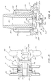
- the automatic sprinkler head 5 shown in Figs. 1 and 2 comprises a housing 6 having a threaded end 7 for screwing into an adaptor (not shown) on a water supply line, and a deflector 8 supported spaced therefrom by depending arsm 9.
- a central, internally threaded boss 10 is supported between the arms 9 and holds the deflector plate 8.
- An adjustment screw 11 is threaded into the boss 10 and a valve plug 12, together with a packing ring 13, when held against the open mouth of the water passage 14 through the head 5, serve to obstruct water flow therefrom onto the deflector 8 for discharge in a predetermined spray pattern over a fire protected area.
- a control, or activator, assembly 15 effects such closure of the valve plug 12.
- control assembly 15 is of a conventional form except for the form of control assembly 15 and cooperating lever means that is utilised.
- a soldered element or a frangible glass bulb has been used for the control assembly 15.
- These bulbs contain a liquid possessing a high temperature coefficient of expansion, but due to the poor heat conductivity of glass, they are relatively slow acting in response to the occurrence of a fire.
- the assembly 15 is constructed of few parts readily capable of assembly, even by automatic machinery, and responds quickly to temperature variation.
- the assembly 15 consists of a laminar construction of two juxtaposed and contacting heat conducting circular fins 16 and 17 coaxial with and contacting an annulus 23 (Fig. 3) of eutectic solder.
- the fins 16 and 17 and solder annulus 23 as well as heat insulators, together with an abutting retaining ring 18 are assembled upon a post 19.
- a separate bent and bifurcated lever 20 is a further component of the control assembly 15.
- this assembly is of simple form and readily capable of being mass produced by automatic machinery. Assembly of the activator 15 upon the sprinkler head 5 can also be achieved simply, preferably by automatic machinery. To achieve this the activator assembly 15 is positioned with one end of the post 19 engaged with the valve plug 12 while the bent lever 20 is inserted between the retaining ring 18 and the adjustment screw 11 on the sprinkler head 5, with a pointed end 21 of the post 9 engaged within a peripheral groove 22 in the lever 20. By suitable adjustment of the screw 11, therefore, the water passage 14 is sealed closed by the valve plug 12. The manner in which automatic operation of the sprinkler head 5 occurs will be made clear in the following description of the second embodiment shown in Fig. 3.
- a similarly formed control assembly 15 is utilised which from Fig. 3 can be seen to incorporate the solder annulus 23 upon a sleeve 24 which has an enlarged head 25.
- the heat fins 16 and 17 have hub portions 26 in contact with each other and between the solder annulus 23 and the head 25.
- a heat insulating washer 27 abuts the outer face of the solder annulus 23 and separates it from the retaining ring 18.
- the sleeve 24 is of heat insulating material.
- the retaining ring 18 surrounds the outer end of the sleeve 24 extending beyond the insulating washer 27.
- a sprinkler head (not shown) of the components shown in this drawing will be achieved.
- all of the components may be pre-assembled upon a modified post 9A having a securing nut 28 at one threaded end 30 and an opposite end 29 provided with a projecting double chamfered annular rib 29A.
- a pair of diametrally opposed levers 31 and 32 are captured upon the post 9A by V-grooved inner ends 33 which partly encircle the post 9A.
- Capturing of the levers 31 and 32 is effected by screwing down the nut 28 so that diverging, external part conical surfaces 34 provided to one side of the inner ends of the levers 31 and 32 engage with an inner peripheral edge 18A of the retaining ring 18 while tha peak 29B of the rib 29A serves as a fulchum for the levers 31 and 32.
- Mounting of the activator to a sprinkler head 5, with the nut 28 loosened, is achieved by engaging the outer end 35 of one of the levers 31 and 32 with the valve plug 12 (Figs. 1 and 2), and the outer end 35 of the other lever with the inner end of the adjustment screw 11. The nut 28 is then tightened to secure the assembly.
- the axes of the levers 31 and 32 are tilted with respect to each other so that when the activator is mounted their conical surfaces 34 bear with force against the ring 18 due to water pressure tending to increase the tilt of the levers 31 and 32.
- the solder annulus 23 When the solder annulus 23 responds to a predetermined temperature and melts it will flow from the space between the hubs 26 of the fins 16 and 17 and the insulating washer 27.
- the retaining ring 18 will then be forceably displaced towards the hubs 26 by the force imposed by the conical surfaces 34, which under the pressure of water in the passageway 14 will cause the levers 31 and 32 to pivot, or tilt, about the fulcrum 29B to narrow the spacing between the ends 35 of the levers 31 and 32.
- the entire activator assembly 15 will be discharged laterally of the sprinkler head 5 and the valve plug will be released.
- FIG. 4 A third embodiment is depicted in Fig. 4 where discharge upon activation of the assembly 15A is effected axially of the sprinkler head 5.
- the deflector plate 8A is fixed upon a pair of slidable extension rods 36 and engages the valve plug 12A which includes a domed spring diaphragm valve 37 urging the deflector 8A downwardly.
- a control assembly 15A incorporates a pair of levers 31A and 32A of modified form.
- the post 9B preferably includes a head 28B adjacent the levers 31A and 32A, preferably with an adjustment nut 30A at its opposite end accessible externally of the head 5.
- the levers 31A and 32A also include inclined ramps 34A while the outer ends 35A of the levers engage within slots 38 internally of the sprinkler head housing 6.
- a domed spring 39 abuts the levers 31A and 32A and applies pressure to the underside of the deflector 8A to effect closure of the valve plug 12A.
- the retaining ring 18 When the solder annulus 23 responds to a predetermined temperature the retaining ring 18 will withdraw from the levers 31A and 32A and allow them to pivot about the post 9B to narrow the spacing between their ends 35A.
- the levers 31A and 32A do not require to be tilted with respect to each other. This will have the effect, under the pressure of the domed spring 39 and the internal water pressure in the passage 14, to unseat the levers 31A and 32A from their grooves 38 for axial discharge downwardly from the sprinkler head 5.
Landscapes
- Health & Medical Sciences (AREA)
- Public Health (AREA)
- Business, Economics & Management (AREA)
- Emergency Management (AREA)
- Fire-Extinguishing By Fire Departments, And Fire-Extinguishing Equipment And Control Thereof (AREA)
Applications Claiming Priority (2)
| Application Number | Priority Date | Filing Date | Title |
|---|---|---|---|
| AU10455/88A AU1045588A (en) | 1986-11-21 | 1987-11-20 | Device for opening a wrapped roll of coins |
| AU10455/88 | 1988-10-18 |
Publications (1)
| Publication Number | Publication Date |
|---|---|
| EP0384068A1 true EP0384068A1 (fr) | 1990-08-29 |
Family
ID=3701436
Family Applications (1)
| Application Number | Title | Priority Date | Filing Date |
|---|---|---|---|
| EP89310752A Withdrawn EP0384068A1 (fr) | 1988-10-18 | 1989-10-18 | Dispositif de déclanchement automatique pour atomiseur |
Country Status (1)
| Country | Link |
|---|---|
| EP (1) | EP0384068A1 (fr) |
Cited By (1)
| Publication number | Priority date | Publication date | Assignee | Title |
|---|---|---|---|---|
| JP2015142809A (ja) * | 2015-05-12 | 2015-08-06 | 能美防災株式会社 | スプリンクラヘッド |
Citations (6)
| Publication number | Priority date | Publication date | Assignee | Title |
|---|---|---|---|---|
| DE200282C (fr) * | ||||
| US4491182A (en) * | 1983-01-05 | 1985-01-01 | Central Sprinkler Corporation | Automatic sprinkler |
| US4508175A (en) * | 1982-11-10 | 1985-04-02 | Central Sprinkler Corporation | Flush pendant or flush horizontal automatic sprinkler head |
| GB2155328A (en) * | 1984-03-13 | 1985-09-25 | Grinnell Fire Protection | Fire protection sprinkler head |
| US4651832A (en) * | 1983-06-23 | 1987-03-24 | Masanove Kubo | Flash type sprinkler head |
| WO1988006469A1 (fr) * | 1987-03-02 | 1988-09-07 | The Reliable Automatic Sprinkler Co., Inc. | Crepine d'incendie decorative a reaction rapide |
-
1989
- 1989-10-18 EP EP89310752A patent/EP0384068A1/fr not_active Withdrawn
Patent Citations (6)
| Publication number | Priority date | Publication date | Assignee | Title |
|---|---|---|---|---|
| DE200282C (fr) * | ||||
| US4508175A (en) * | 1982-11-10 | 1985-04-02 | Central Sprinkler Corporation | Flush pendant or flush horizontal automatic sprinkler head |
| US4491182A (en) * | 1983-01-05 | 1985-01-01 | Central Sprinkler Corporation | Automatic sprinkler |
| US4651832A (en) * | 1983-06-23 | 1987-03-24 | Masanove Kubo | Flash type sprinkler head |
| GB2155328A (en) * | 1984-03-13 | 1985-09-25 | Grinnell Fire Protection | Fire protection sprinkler head |
| WO1988006469A1 (fr) * | 1987-03-02 | 1988-09-07 | The Reliable Automatic Sprinkler Co., Inc. | Crepine d'incendie decorative a reaction rapide |
Cited By (1)
| Publication number | Priority date | Publication date | Assignee | Title |
|---|---|---|---|---|
| JP2015142809A (ja) * | 2015-05-12 | 2015-08-06 | 能美防災株式会社 | スプリンクラヘッド |
Similar Documents
| Publication | Publication Date | Title |
|---|---|---|
| US4976320A (en) | Concealed sprinkler with drop down deflector assembly, and improved fusible valve lever assembly | |
| US4880063A (en) | Adjustable concealed sprinkler | |
| US5094298A (en) | Fire sprinkler apparatus | |
| US4766961A (en) | Decorative quick response sprinkler | |
| US5083616A (en) | Ceiling sprinkler | |
| US5097906A (en) | Concealed automatic sprinkler | |
| KR101821829B1 (ko) | 스프링클러 헤드 | |
| US3874455A (en) | Automatic sprinkler valve | |
| US4217961A (en) | Water sprinklers | |
| US5299645A (en) | Fire extinguisher sprinkler construction | |
| US3783947A (en) | Automatic sprinkler head | |
| US5022468A (en) | Automatic sprinkler activator | |
| US4651832A (en) | Flash type sprinkler head | |
| US4922944A (en) | Melting safety device for gas system of hydropneumatic pressure accumulators | |
| US3838705A (en) | Heat responsive safety device for gate valves | |
| US4343364A (en) | Sprinkler head construction | |
| US4623023A (en) | Sprinkler head | |
| WO2007108899A2 (fr) | Gicleur avec levier limité en mouvement | |
| US4570720A (en) | Sprinkler head | |
| EP0384068A1 (fr) | Dispositif de déclanchement automatique pour atomiseur | |
| CA1048084A (fr) | Tete d'extincteur automatique | |
| KR960008948Y1 (ko) | 스프링 쿨러헤드 | |
| US4298068A (en) | Heat sensitive release devices | |
| JP3082075B2 (ja) | スプリンクラーヘッド用感熱分解部分 | |
| US4899777A (en) | Thermally activated pressure relief plug |
Legal Events
| Date | Code | Title | Description |
|---|---|---|---|
| PUAI | Public reference made under article 153(3) epc to a published international application that has entered the european phase |
Free format text: ORIGINAL CODE: 0009012 |
|
| AK | Designated contracting states |
Kind code of ref document: A1 Designated state(s): AT BE CH DE ES FR GB GR IT LI LU NL SE |
|
| 17P | Request for examination filed |
Effective date: 19900925 |
|
| 17Q | First examination report despatched |
Effective date: 19911202 |
|
| STAA | Information on the status of an ep patent application or granted ep patent |
Free format text: STATUS: THE APPLICATION IS DEEMED TO BE WITHDRAWN |
|
| 18D | Application deemed to be withdrawn |
Effective date: 19920414 |