EP0384157B1 - Soupape à deux voies à commande pilotée hydrauliquement en manière à siège - Google Patents
Soupape à deux voies à commande pilotée hydrauliquement en manière à siège Download PDFInfo
- Publication number
- EP0384157B1 EP0384157B1 EP90101628A EP90101628A EP0384157B1 EP 0384157 B1 EP0384157 B1 EP 0384157B1 EP 90101628 A EP90101628 A EP 90101628A EP 90101628 A EP90101628 A EP 90101628A EP 0384157 B1 EP0384157 B1 EP 0384157B1
- Authority
- EP
- European Patent Office
- Prior art keywords
- pressure
- valve
- built
- face
- closing
- Prior art date
- Legal status (The legal status is an assumption and is not a legal conclusion. Google has not performed a legal analysis and makes no representation as to the accuracy of the status listed.)
- Expired - Lifetime
Links
Images


Classifications
-
- F—MECHANICAL ENGINEERING; LIGHTING; HEATING; WEAPONS; BLASTING
- F15—FLUID-PRESSURE ACTUATORS; HYDRAULICS OR PNEUMATICS IN GENERAL
- F15B—SYSTEMS ACTING BY MEANS OF FLUIDS IN GENERAL; FLUID-PRESSURE ACTUATORS, e.g. SERVOMOTORS; DETAILS OF FLUID-PRESSURE SYSTEMS, NOT OTHERWISE PROVIDED FOR
- F15B13/00—Details of servomotor systems ; Valves for servomotor systems
- F15B13/02—Fluid distribution or supply devices characterised by their adaptation to the control of servomotors
- F15B13/04—Fluid distribution or supply devices characterised by their adaptation to the control of servomotors for use with a single servomotor
- F15B13/0401—Valve members; Fluid interconnections therefor
- F15B13/0405—Valve members; Fluid interconnections therefor for seat valves, i.e. poppet valves
Definitions
- the invention is based on a hydraulically controllable 2-way cartridge valve in seat valve design according to the preamble of the main claim.
- the built-in valve has an actuating device in which an actuating piston is arranged in a separate housing part, which in turn can be mounted on a commercially available standard cartridge like a cover.
- the pressure surfaces for opening and closing are formed on opposite surfaces of the same actuating piston in the actuating device.
- the hydraulically pilot-operated 2-way cartridge valve according to the invention with the characterizing features of the main claim has the advantage that it allows a simpler and more cost-effective design with high functional reliability while maintaining the previous range of functions. Due to the fact that in the actuating device the space relieved of the tank is always between the pressure surfaces for opening and closing, there can be no mutual interference between the two pressure spaces by leakage oil. The effort for sealing on the actuating piston is thus less and can be sufficient with a seal as in the area of usual slide / housing tolerances and thus also reduce the friction in the valve. From each other Separate components such as the closing body and the locking piston run in two separate housing parts, which enables simple, inexpensive production. The locking piston itself is only acted upon on one side by the control pressure medium.
- the built-in valve can continue to be designed by connecting its pressure chambers appropriately so that it can be used as an unblockable check valve in both flow directions.
- the cartridge valve can therefore be used advantageously in safety circuits to meet a wide variety of requirements.
- the actual cartridge can still be used separately for other functions.
- a design according to claim 2 is particularly expedient, as a result of which almost all of the measures required for the actuating device can be accommodated in the cover, so that largely a standardized, commercially available standard cartridge with an associated housing can be used. This enables an inexpensive construction.
- Formations according to claims 3 to 5 are also expedient, whereby a simple and cheap construction is favored in each case.
- a non-positive connection between the closing body and the actuating piston is sufficient, with all moving parts being guided in separate components, so that the built-in valve can be produced easily and inexpensively.
- the actuating piston is arranged directly on the closing body, so that when the opening pressure surface on the actuating piston is acted upon, the closing body is taken along during an opening stroke.
- This not only leads to greater functional reliability of the built-in valve, but also enables a lower flow resistance, since the built-in valve does not act when this open-pressure surface is pressurized in the main flow must be flowed through against spring force.
- the built-in valve now comes with 5 pressure chambers, with only one pressure chamber in the cover.
- An embodiment according to claim 7 or 8 favors simple manufacture of the cartridge valve, especially since the pressure-relieved space is limited by the separating surface between the two housing parts.
- the locking piston is additionally loaded by a spring.
- the closing pressure surface on the locking piston can be of the same size as the sum of the ring surface and the circular surface on the closing body. This favors a compact design.
- the spring ensures a non-positive coupling of the locking piston and closing body and also promotes a faster closing function of the cartridge valve. In certain operating states, the forward resistance when flowing through the cartridge is not adversely affected by the spring.
- the spring also enables an exact assignment between the signal of the position monitoring and the position of the locking piston.
- the built-in valve is used in a safety circuit, as is used in particular in plastic machines or presses for controlling the locking cylinder or in comparable systems. Further advantageous embodiments result from the remaining claims, the description and the drawing.
- FIG. 1 shows a longitudinal section through a first 2-way cartridge valve in a simplified representation
- FIG. 2 shows a longitudinal section through a second exemplary embodiment of the cartridge valve
- FIG. 1 shows a hydraulically pilot-controllable, two-way cartridge valve 10 constructed in the manner of a poppet valve, which essentially consists of a housing 12 accommodating a valve cartridge 11 and a cover 14 accommodating an actuating device 13.
- the housing 12 has a recess 15, to which a first connection 16 labeled A in the axial direction and a second connection 17 labeled B lead in the radial direction.
- the actual valve cartridge 11 is inserted into the recess 15, so that its closing body 19, which is mounted in a cartridge sleeve 18, controls the connection between the two connections 16, 17.
- the cartridge case 18 is further secured by a cartridge guide 21 inserted into the recess 15, which also acts as a partition between different pressurized chambers.
- the closing body 19 is guided in the cartridge case 18 with a guide part 22, the outer diameter of which is larger than the associated seat diameter 23. In this way, a circular surface 24 is formed on the closing body 19, which in the illustrated blocking position of the closing body 19 is dependent on the pressure in the first connection 16 is acted upon, while an associated annular surface 25 is acted upon by the pressure in the second connection 17.
- the cover 14 has a stepped bore 29 which runs coaxially to the recess 15 and to the first section 31 of large diameter adjoins a second section 32 of smaller diameter.
- an actuating piston 33 is guided tightly and slidably, while in the inner section 32 a locking piston 34 is guided tightly and slidably.
- Actuating piston 33 and locking piston 34 are formed in one piece with one another and form parts of the actuating device 13.
- the actuating piston 33 is non-positively coupled to the closing body 19 via a plunger 35, the plunger 35 being guided tightly and slidingly in the partition wall 21.
- the cross-sectional area of the plunger 35 is considerably smaller than the annular surface 25 or the circular surface 24.
- the diameter of the actuating piston 33 is larger than the diameter of the locking piston 34, which in turn is larger than the diameter of the guide part 22 on the closing body 19 and locking pistons 34 together delimit in the first section 31 an annular space 36 which is continuously relieved to the tank 28 via a channel 37.
- the actuating piston 33 borders with an open pressure surface 38 to a first pressure chamber 39, into which the plunger 35 protrudes with one end and which optionally has the pressure from a via a control channel 41 and a 4/2 switching valve 42 Pump or pressure medium source 43 can be acted upon or relieved to the tank 28.
- the locking piston 34 encloses a second pressure chamber 44 in the second section 32, the pressure of which acts on a circular closing pressure surface 45 of the locking piston 34. Furthermore, a closing spring 46 loading the locking piston 34 is arranged in the second pressure chamber 44. The position of the locking piston 34 can be queried via an electromechanical displacement sensor 47.
- the second pressure chamber 44 is directly connected to the second connection 17 via a second control channel 48. The pressure in the second Pressure chamber 44 can be queried via an electro-hydraulic pressure sensor 49.
- the moving parts such as the actuating piston 33, plunger 35 and closing body 19 are each mounted in separate, fixed components such as cover 14, cartridge guide 21 and cartridge sleeve 18 or housing 12, so that simple manufacture is possible.
- the surface gradation in the built-in valve 10 is selected such that the sum of the annular surface 25 and the opening pressure surface 38 is greater than the closing pressure surface 45, the closing force of the closing spring 46 possibly also having to be taken into account.
- the closing pressure surface 45 is larger than the sum of the annular surface 25 and the circular surface 24, wherein the closing pressure surface 45 can also be selected to be the same size in the limit case when the closing spring 46 is used.
- the circular area 24 is selected to be larger than the ring area 25.
- the mode of operation of the built-in valve 10 is explained as follows, it being assumed that the built-in valve 10 is used in a safety circuit in which a flow through the valve cartridge 11 generally takes place in both directions.
- the function of the built-in valve 10 is influenced by a switching valve 42, which is controlled as a function of the position of a safety device 51, which can be the protective door in an injection molding machine, for example. There are thus four switching states in which the built-in valve 10 has to meet predetermined safety requirements.
- the built-in valve 10 works like a check valve in these states, the closing body 19 assuming the drawn blocking position and preventing flow from B to A .
- This check valve function is also supported by the closing spring 46, so that this function is retained in the borderline case if the closing pressure surface 45 is chosen to be the same size as the sum of the circular surface 24 and the annular surface 25. From the second pressure chamber 44 past the outer surface of the locking piston 34 leaking oil at most enters the relieved space 36, so that no malfunction can occur due to a pressure build-up in the space 39 due to leakage oil.
- FIG. 2 shows a longitudinal section through a second cartridge valve 60, which differs from the first cartridge valve 10 according to FIG. 1 as follows, the same reference numerals being used for the same components.
- the built-in valve 60 has a closing body 61, at the upper end of which the actuating piston 62 is attached directly.
- the closing body 61 with integrated actuating piston 62 is tightly and slidably guided in a cartridge case 63, so that the first pressure chamber 39 with the associated, now ring-shaped open pressure surface 38 is arranged inside the cartridge case 63 and thus also within the housing 12.
- the relieved space 36 now lies within the housing 12 and is delimited by the cover 14 in the separating surface 64.
- the cover 14 instead of a stepped bore, the cover 14 now has a simple cylindrical bore 65, in which the locking piston 34 is guided in a tight and sliding manner.
- the locking piston 34 itself is a simple cylindrical rotating part and rests with its lower end in the relieved space 36 on the actuating piston 62.
- the conditions for grading the area are met as with the first built-in valve 10.
- the arrangement of the actuating piston 62 directly on the closing body 61 has the advantage that the number of pressure chambers is reduced from 6 to 5 now. Furthermore, there is a simpler design for the actuating device, which manages with a simple cylindrical bore 65 and a suitable cylindrical locking piston 34.
- the frictional coupling between the locking piston 34 and the closing body 61 takes place advantageously in the relieved space 36, which at the same time also borders on the parting plane 64 between the housing 12 and the cover 14.
- the arrangement of the actuating piston 62 on the closing body 61 has the advantage that when the opening pressure surface 38 is pressurized, the closing body 61 is carried along in the opening direction and thus when the valve cartridge flows through it no additional spring force has to be overcome.
- the built-in valve 60 has the same principle of operation as the first built-in valve 10, in that it enables free flow from port A to port B in the cross position of the switching valve 42, while acting in the reverse direction of flow from B to A as a check valve and blocking the flow . By actuating the switching valve 42 in parallel position with pressurization of the open pressure surface 38, this locking is released, so that a free flow in both directions is possible.
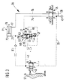
- FIG. 3 shows the second built-in valve 60 in a simplified representation in connection with a safety circuit 70, such as is used for a locking cylinder 71 in a plastic machine.
- the first port A of the built-in valve 60 is connected to a first port 72 on the closing side 73 on the locking cylinder.
- the second connection B of the built-in valve 60 is connected via a working line 74 to a 4/3-way valve 75.
- a second working line 76 leads from the directional control valve 75 to a second connection 77 on the opening side 78 of the locking cylinder 71.
- the directional control valve 75 is also connected to the pump 43 and the tank 28.
- the pressure of the pump 43 is fed via a control line 79 to the 4/2 switching valve 42 which, via the first control channel 41, either applies pump pressure to the first pressure chamber 39 or unloads it to the tank.
- the protective door 51 in the plastic machine is used here as a safety device for actuating the switching valve 42. It is also for pressure relief a line 81 is provided which leads from the closing side 73 to the switching valve 42 and in which a check valve and a throttle point are arranged.
- the built-in valve 60 serves as a closing safety device in the safety circuit 70 and, in addition to the directional control valve 75, is the second element responsible for safety. It is therefore arranged between the closing side 73 of the cylinder 71 and the directional valve 75.
- the hydraulic actuation of the locking device 60 takes place via the switching valve 42 actuated by the movable protective door 51.
- the built-in valve 60 serving as a locking device must be installed in such a way that the switching valve 42 assumes its spring-centered parallel position when the protective door 51 is closed and due to the pressurization of the open pressure surface 38 on the actuating piston 33, the lock in the installation valve 60 is released so that in the parallel position of the directional control valve 75 the pressure medium flows from the pump 43 via the working line 74 and the open installation valve 60 to the closing side 73 and the extending piston rod in the locking cylinder 71 can close a shape.
- the switching valve 42 is forcibly brought into its cross position by this and thus the locking in the built-in valve 60 is effective, so that closing of the mold is prevented at all times by the closing cylinder 71 being extended.
- the built-in valve 60 works in the safety circuit 70 in the same way as was explained in connection with the first built-in valve 10 on the basis of the 4 switching states.
- the first switching state results when the directional valve 75 is switched into its parallel position to close the mold while the protective door 51 is still open and the switching valve 42 thus relieves the first control channel 41 to the tank.
- the safety function of the built-in valve 60 is effective and the closing body 61 remains in the blocking position by pressure via line 48 into the second pressure chamber 44.
- the second switching state results when the directional valve 75 again assumes its parallel position, but the protective door 51 is closed. In this case, the built-in valve 60 is not locked, ie the valve cartridge is opened by pressure via line 41 into the first pressure chamber 39.
- the third switching state results when the directional valve 75 assumes its cross position to open the mold while the protective door 51 is still open. Even then the valve cartridge is open.
- the fourth switching state results in a corresponding manner when the protective door 51 is closed in the cross position of the directional control valve 75 and thus the closing body 61 assumes its open position when the lock in the built-in valve 60 is released.
- the pressure build-up for the closing movement in the built-in valve 60 is brought about by control oil which reaches the closing pressure surface 45 from the second connection B via the short, second control channel 48. Since this short control channel 48 is formed directly in the block 12, 14, the reliable function of the closing movement when the control line 41 is relieved and the oil pressure in the second port B is present and thus does not require any additional control.
- the displacement sensor 47 enables the control of the two switching states open and closed of the closing body 61.
- the closing body 61 has an overlap stroke 52 in which the electrical signaling for the switching positions valve open or closed takes place.
- the cartridge valve can also be used without position monitoring and can then be used as a hydraulically unlockable check valve.
- the built-in valve can also be used in such a way that the second control channel 48 is connected to the free port B of a 4/2-way valve 42, so that the opening pressure area and the closing pressure area alternately via a 4/2-pilot valve with the Pressurized or relieved to the tank. There is then a fixed association between the position of the protective door 51 and the position of the safety cartridge.
- the built-in valve by connecting the pressure chambers appropriately, it can also be achieved that the valve can also function as a check valve in the other flow direction.
Landscapes
- Engineering & Computer Science (AREA)
- Physics & Mathematics (AREA)
- Fluid Mechanics (AREA)
- Mechanical Engineering (AREA)
- General Engineering & Computer Science (AREA)
- Safety Valves (AREA)
Claims (14)
- Soupape incorporée à deux voies, à commande pilotée hydrauliquement, du type à siège (10, 60), notamment pour des circuits de sécurité, avec un corps de fermeture (19, 61) disposé dans un carter (12) et un dispositif de réglage (13) associé à ce corps et disposé au moins partiellement dans un couvercle (14) monté sur le carter (12), soupape dans laquelle le corps de fermeture (19, 61) commande la communication entre un premier raccordement (16) arrivant axialement à ce corps et un second raccordement (17) arrivant radialement, tandis que la zone de siège se trouvant entre ces raccordements a un plus petit diamètre (23) qu'une partie de guidage (22) du corps de fermeture (19, 61), de sorte que sur ce corps sont ménagées une surface circulaire (24) susceptible d'être sollicitée par la pression régnant dans le premier raccordement (16) et une surface annulaire (25) susceptible d'être sollicitée par la pression régnant dans le second raccordement (17), et avec, dans le dispositif de réglage (13), un piston de réglage (33, 62) dont le diamètre est supérieur à celui de la partie de guidage (22) et qui comporte sur son côté tourné vers le corps de fermeture (19, 61) une surface de pression d'ouverture (38), pouvant être sollicitée soit par une pression de pompe soit par une faible pression, et avec, dans le dispositif de réglage (13), une surface de pression de fermeture (45) exerçant une action contraire à celle de la surface de pression d'ouverture (38) et tout au moins égale ou supérieure à la somme de la surface circulaire (24) et de la surface annulaire (25), et avec une chambre (36) déchargée vers le réservoir, soupape caractérisée en ce que la surface de pression de fermeture (45) revêt la forme d'une surface circulaire et se situe à l'extrémité d'un piston de verrouillage (34) dont le diamètre est au moins égal ou supérieur à celui de la partie de guidage (22) sur le corps de fermeture (19, 61), en ce que ce piston de verrouillage (34) est disposé en raccordement avec le piston de réglage (33, 62) et délimite conjointement avec celui-ci la chambre déchargée (36), et en ce que cette chambre (36) est disposée entre les chambres de pression (39, 44) associées à la surface de pression d'ouverture (38) et à la surface de pression de fermeture (45).
- Soupape selon la revendication 1, caractérisée en ce que le piston de réglage (33), le piston de verrouillage (34), et la chambre déchargée (36) contiguë à celui-ci, sont disposés dans le couvercle (14) dans lequel se trouve notamment, la première chambre de pression (39).
- Soupape selon la revendication 1 ou la revendication 2, caractérisée en ce que le dispositif de réglage (13) comporte un poussoir (35) qui couple par adhérence le piston de réglage (33) au corps de fermeture (19) et qui est guidé pour glisser de façon étanche dans une paroi de séparation (21) disposée dans le carter (12) et séparant la chambre de pression (39) associée à la surface de pression d'ouverture (38), d'une chambre de commande (26) déchargée, associée au corps de fermeture (19).
- Soupape selon la revendication 3, caractérisée en ce que le piston de réglage (33) est réalisé d'un seul tenant avec le piston de verrouillage (34), tandis que le piston de réglage (33), le poussoir (35) et le corps de fermeture (19) forment des éléments constitutifs distincts les uns des autres qui sont respectivement guidés dans des parties constitutives distinctes (14, 21, 18).
- Soupape selon la revendication 3 ou la revendication 4, caractérisée en ce que la surface de section transversale du poussoir (35) est beaucoup plus petite que la surface annulaire (25) sur le corps de fermeture (19), et la surface annulaire (25) est plus petite que la surface circulaire (24) sur le corps de fermeture (19).
- Soupape selon la revendication 1, caractérisée en ce que le piston de réglage (62) est formé sur le corps de fermeture (61) et en ce qu'ils sont disposés conjointement de la façon que la première chambre de pression (39) soit associée à la surface de pression d'ouverture (38) à l'intérieur du carter (12).
- Soupape selon la revendication 6, caractérisée en ce que la chambre déchargée (36), placée entre les deux chambres de pression (39, 44), se situe à l'intérieur du carter (12) et est délimitée par une surface de séparation (64) qui sépare le carter (12) du couvercle (14) lorsque celui-ci est monté (figure 2).
- Soupape selon la revendication 6 ou la revendication 7, caractérisée en ce que le couvercle (14) comporte un alésage cylindrique (65) dans lequel est guidé le piston de verrouillage (34), en ce que ce piston de verrouillage est réalisé sous la forme d'un cylindre plongeur et s'applique contre le piston de réglage (62) dans la chambre (36) déchargée en pression.
- Soupape selon l'une ou plusieurs des revendications 1 à 8, caractérisée en ce que la somme de la surface annulaire (25) et de La surface de pression d'ouverture (38) est supérieure à la surface de pression de fermeture (45) sur le piston de verrouillage (34).
- Soupape selon l'une ou plusieurs des revendications 1 à 9, caractérisée en ce que le piston de verrouillage (34) est sollicité par un ressort (46) dans le sens de fermeture du corps de fermeture (19, 61).
- Soupape selon l'une ou plusieurs des revendications 1 à 10, caractérisée en ce que, dans le couvercle (14) est agencé un dispositif (47) associé au piston de verrouillage (34) pour la surveillance de la position du piston de fermeture.
- Soupape selon l'une des revendications 1 à 11, caractérisée en ce qu'il est mis en oeuvre pour un circuit de sécurité (70), notamment pour un vérin de fermeture (71) d'une machine ou d'une presse à matière plastique.
- Soupape selon l'une des revendications 1 à 12, caractérisée en ce qu'elle est branchée conjointement avec un distributeur (75) en série entre un raccordement à protéger (72) d'un moteur hydraulique à double effet (71) et une source de fluide sous pression (43), tandis que l'autre raccordement (77) du moteur hydraulique (71) est relié au distributeur (75), et en ce que la surface de pression d'ouverture (38) est susceptible d'être sollicitée par la pression de pompe ou bien d'être déchargée vers le réservoir (28) par l'intermédiaire d'une vanne de commutation (42) actionnée par un dispositif de sécurité.
- Soupape selon la revendication 13, caractérisée en ce que son premier raccordement A (16) est relié au moteur hydraulique (71) tandis que son second raccordement B (17) est relié au distributeur (75), et en ce que, notamment, la surface de pression de fermeture (45) est constamment sollicitée par la pression régnant dans la première canalisation de fonctionnement (74) entre la soupape incorporée (60) et le distributeur (75).
Applications Claiming Priority (2)
| Application Number | Priority Date | Filing Date | Title |
|---|---|---|---|
| DE3905015 | 1989-02-18 | ||
| DE3905015A DE3905015A1 (de) | 1989-02-18 | 1989-02-18 | Hydraulisch vorsteuerbares 2-wege-einbauventil in sitzventilbauweise |
Publications (3)
| Publication Number | Publication Date |
|---|---|
| EP0384157A2 EP0384157A2 (fr) | 1990-08-29 |
| EP0384157A3 EP0384157A3 (fr) | 1991-04-17 |
| EP0384157B1 true EP0384157B1 (fr) | 1994-01-12 |
Family
ID=6374419
Family Applications (1)
| Application Number | Title | Priority Date | Filing Date |
|---|---|---|---|
| EP90101628A Expired - Lifetime EP0384157B1 (fr) | 1989-02-18 | 1990-01-27 | Soupape à deux voies à commande pilotée hydrauliquement en manière à siège |
Country Status (2)
| Country | Link |
|---|---|
| EP (1) | EP0384157B1 (fr) |
| DE (2) | DE3905015A1 (fr) |
Families Citing this family (3)
| Publication number | Priority date | Publication date | Assignee | Title |
|---|---|---|---|---|
| DE102006055393A1 (de) * | 2006-05-05 | 2007-11-08 | Robert Bosch Gmbh | Ventil und hydraulische Steueranordnung |
| DE102009025827A1 (de) * | 2009-05-18 | 2010-11-25 | Bucyrus Dbt Europe Gmbh | Hydraulikschaltvorrichtung für die Mobilhydraulik, mobile Hydraulikmaschine und Ventileinheit |
| IT202200020595A1 (it) * | 2022-10-06 | 2024-04-06 | Pnr Italia S R L | Gruppo valvolare per il controllo e/o la regolazione della portata di un fluido in pressione |
Family Cites Families (3)
| Publication number | Priority date | Publication date | Assignee | Title |
|---|---|---|---|---|
| DE2835771A1 (de) * | 1978-08-16 | 1980-02-28 | Schwelm & Towler Hydraulics | Anordnung zur aussteuerung eines cartridgeelementes |
| DE3135273A1 (de) * | 1981-09-05 | 1983-03-24 | Klöckner-Humboldt-Deutz AG, 5000 Köln | Hydraulisches steuergeraet |
| DE3741521C1 (en) * | 1987-12-08 | 1989-02-16 | Hemscheidt Maschf Hermann | 2/2-way seat valve |
-
1989
- 1989-02-18 DE DE3905015A patent/DE3905015A1/de not_active Withdrawn
-
1990
- 1990-01-27 DE DE90101628T patent/DE59004167D1/de not_active Expired - Fee Related
- 1990-01-27 EP EP90101628A patent/EP0384157B1/fr not_active Expired - Lifetime
Also Published As
| Publication number | Publication date |
|---|---|
| DE3905015A1 (de) | 1990-08-23 |
| EP0384157A3 (fr) | 1991-04-17 |
| EP0384157A2 (fr) | 1990-08-29 |
| DE59004167D1 (de) | 1994-02-24 |
Similar Documents
| Publication | Publication Date | Title |
|---|---|---|
| DE112019002974T5 (de) | Hydraulischer Dämpfer | |
| EP0066274B1 (fr) | Arrangement de vannes pour augmenter la vitesse de sortie d'un vérin | |
| DE3323363A1 (de) | Vorgesteuertes druckreduzierventil | |
| EP0279315B1 (fr) | Dispositif de commande hydraulique | |
| EP0103250B1 (fr) | Soupape de contrôle pour contrôle hydraulique | |
| DE19931142A1 (de) | Hydraulische Ventilanordnung mit Verriegelungsfunktion | |
| WO1998007611A1 (fr) | Dispositif de commande electrohydraulique | |
| EP0975856B1 (fr) | Soupape avec dispositif de commande hydraulique | |
| EP0384157B1 (fr) | Soupape à deux voies à commande pilotée hydrauliquement en manière à siège | |
| DE2461896A1 (de) | Stelleinrichtung | |
| DE2602381A1 (de) | Zweistufige stroemungsmengen-steuerventilanordnung | |
| DE2849704C2 (fr) | ||
| DE4234626A1 (de) | Druckgesteuertes Ventil | |
| DE7626855U1 (de) | Steuerventil | |
| DE4119297C2 (de) | Hydraulische Ventileinrichtung zur Steuerung des Leerlaufs, der Druckbegrenzung und der Lastdruckkompensation | |
| DE2305579A1 (de) | Durch einen druck eines fliessfaehigen mediums betaetigtes fernsteuersystem | |
| DE3022592C2 (de) | Schiebersteuerventil | |
| DE4002927A1 (de) | Hydraulische steuerventileinrichtung | |
| DE102008059437B3 (de) | Hydraulisches Steuerventil mit zwei Steuerkolben für einen einseitig arbeitenden Differentialzylinder | |
| DE4304117C2 (de) | Druckminderventil in Kolbenschieber-Bauweise | |
| DE19757157C2 (de) | Hydraulischer Linearantrieb | |
| DE10001033B4 (de) | Hydraulischer Stellantrieb für eine Kraftfahrzeugservolenkung | |
| DE19641540C2 (de) | Hydraulisches Sicherheitsventil | |
| DE19925204B4 (de) | Entsperrbares Lasthalteventil | |
| DE19522744B4 (de) | Elektrohydraulische Steuervorrichtung |
Legal Events
| Date | Code | Title | Description |
|---|---|---|---|
| PUAI | Public reference made under article 153(3) epc to a published international application that has entered the european phase |
Free format text: ORIGINAL CODE: 0009012 |
|
| AK | Designated contracting states |
Kind code of ref document: A2 Designated state(s): DE FR GB IT |
|
| PUAL | Search report despatched |
Free format text: ORIGINAL CODE: 0009013 |
|
| AK | Designated contracting states |
Kind code of ref document: A3 Designated state(s): DE FR GB IT |
|
| 17P | Request for examination filed |
Effective date: 19911008 |
|
| RAP3 | Party data changed (applicant data changed or rights of an application transferred) |
Owner name: ROBERT BOSCH GMBH |
|
| 17Q | First examination report despatched |
Effective date: 19920812 |
|
| GRAA | (expected) grant |
Free format text: ORIGINAL CODE: 0009210 |
|
| AK | Designated contracting states |
Kind code of ref document: B1 Designated state(s): DE FR GB IT |
|
| PGFP | Annual fee paid to national office [announced via postgrant information from national office to epo] |
Ref country code: GB Payment date: 19940202 Year of fee payment: 5 |
|
| ET | Fr: translation filed | ||
| GBT | Gb: translation of ep patent filed (gb section 77(6)(a)/1977) |
Effective date: 19940117 |
|
| REF | Corresponds to: |
Ref document number: 59004167 Country of ref document: DE Date of ref document: 19940224 |
|
| ITF | It: translation for a ep patent filed | ||
| PLBE | No opposition filed within time limit |
Free format text: ORIGINAL CODE: 0009261 |
|
| STAA | Information on the status of an ep patent application or granted ep patent |
Free format text: STATUS: NO OPPOSITION FILED WITHIN TIME LIMIT |
|
| 26N | No opposition filed | ||
| PG25 | Lapsed in a contracting state [announced via postgrant information from national office to epo] |
Ref country code: GB Effective date: 19950127 |
|
| PGFP | Annual fee paid to national office [announced via postgrant information from national office to epo] |
Ref country code: FR Payment date: 19950131 Year of fee payment: 6 |
|
| GBPC | Gb: european patent ceased through non-payment of renewal fee |
Effective date: 19950127 |
|
| PG25 | Lapsed in a contracting state [announced via postgrant information from national office to epo] |
Ref country code: FR Effective date: 19960930 |
|
| REG | Reference to a national code |
Ref country code: FR Ref legal event code: ST |
|
| PGFP | Annual fee paid to national office [announced via postgrant information from national office to epo] |
Ref country code: DE Payment date: 20030225 Year of fee payment: 14 |
|
| PG25 | Lapsed in a contracting state [announced via postgrant information from national office to epo] |
Ref country code: DE Free format text: LAPSE BECAUSE OF NON-PAYMENT OF DUE FEES Effective date: 20040803 |
|
| PG25 | Lapsed in a contracting state [announced via postgrant information from national office to epo] |
Ref country code: IT Free format text: LAPSE BECAUSE OF NON-PAYMENT OF DUE FEES;WARNING: LAPSES OF ITALIAN PATENTS WITH EFFECTIVE DATE BEFORE 2007 MAY HAVE OCCURRED AT ANY TIME BEFORE 2007. THE CORRECT EFFECTIVE DATE MAY BE DIFFERENT FROM THE ONE RECORDED. Effective date: 20050127 |