EP0384236A1 - Cabine d'atomisation à poudre avec dispositif pour guider le gaz brut dans un courant aspirateur d'un séparateur - Google Patents
Cabine d'atomisation à poudre avec dispositif pour guider le gaz brut dans un courant aspirateur d'un séparateur Download PDFInfo
- Publication number
- EP0384236A1 EP0384236A1 EP90102538A EP90102538A EP0384236A1 EP 0384236 A1 EP0384236 A1 EP 0384236A1 EP 90102538 A EP90102538 A EP 90102538A EP 90102538 A EP90102538 A EP 90102538A EP 0384236 A1 EP0384236 A1 EP 0384236A1
- Authority
- EP
- European Patent Office
- Prior art keywords
- suction
- powder
- outlet opening
- opening
- spray booth
- Prior art date
- Legal status (The legal status is an assumption and is not a legal conclusion. Google has not performed a legal analysis and makes no representation as to the accuracy of the status listed.)
- Granted
Links
Images

Classifications
-
- B—PERFORMING OPERATIONS; TRANSPORTING
- B05—SPRAYING OR ATOMISING IN GENERAL; APPLYING FLUENT MATERIALS TO SURFACES, IN GENERAL
- B05B—SPRAYING APPARATUS; ATOMISING APPARATUS; NOZZLES
- B05B14/00—Arrangements for collecting, re-using or eliminating excess spraying material
- B05B14/40—Arrangements for collecting, re-using or eliminating excess spraying material for use in spray booths
- B05B14/48—Arrangements for collecting, re-using or eliminating excess spraying material for use in spray booths specially adapted for particulate material
-
- Y—GENERAL TAGGING OF NEW TECHNOLOGICAL DEVELOPMENTS; GENERAL TAGGING OF CROSS-SECTIONAL TECHNOLOGIES SPANNING OVER SEVERAL SECTIONS OF THE IPC; TECHNICAL SUBJECTS COVERED BY FORMER USPC CROSS-REFERENCE ART COLLECTIONS [XRACs] AND DIGESTS
- Y02—TECHNOLOGIES OR APPLICATIONS FOR MITIGATION OR ADAPTATION AGAINST CLIMATE CHANGE
- Y02P—CLIMATE CHANGE MITIGATION TECHNOLOGIES IN THE PRODUCTION OR PROCESSING OF GOODS
- Y02P70/00—Climate change mitigation technologies in the production process for final industrial or consumer products
- Y02P70/10—Greenhouse gas [GHG] capture, material saving, heat recovery or other energy efficient measures, e.g. motor control, characterised by manufacturing processes, e.g. for rolling metal or metal working
-
- Y—GENERAL TAGGING OF NEW TECHNOLOGICAL DEVELOPMENTS; GENERAL TAGGING OF CROSS-SECTIONAL TECHNOLOGIES SPANNING OVER SEVERAL SECTIONS OF THE IPC; TECHNICAL SUBJECTS COVERED BY FORMER USPC CROSS-REFERENCE ART COLLECTIONS [XRACs] AND DIGESTS
- Y10—TECHNICAL SUBJECTS COVERED BY FORMER USPC
- Y10S—TECHNICAL SUBJECTS COVERED BY FORMER USPC CROSS-REFERENCE ART COLLECTIONS [XRACs] AND DIGESTS
- Y10S118/00—Coating apparatus
- Y10S118/07—Hoods
-
- Y—GENERAL TAGGING OF NEW TECHNOLOGICAL DEVELOPMENTS; GENERAL TAGGING OF CROSS-SECTIONAL TECHNOLOGIES SPANNING OVER SEVERAL SECTIONS OF THE IPC; TECHNICAL SUBJECTS COVERED BY FORMER USPC CROSS-REFERENCE ART COLLECTIONS [XRACs] AND DIGESTS
- Y10—TECHNICAL SUBJECTS COVERED BY FORMER USPC
- Y10S—TECHNICAL SUBJECTS COVERED BY FORMER USPC CROSS-REFERENCE ART COLLECTIONS [XRACs] AND DIGESTS
- Y10S55/00—Gas separation
- Y10S55/46—Spray booths
Definitions
- the invention relates to a powder spray booth of the type highlighted in the preamble of claim 1.
- a powder booth of the type defined at the outset is known from British Patent Specification 13 15 671.
- a trough-shaped bottom and a vertical rear wall are formed between side walls by a common flat line which starts from the lower edge of an injection opening, is led up on the outlet side and from above into the filter device mounted on a movable carriage is deflected.
- the front wall of this line has a rectangular opening, in front of which there is at a distance a diaphragm protruding from this opening on all sides, which forms in the wall plane a suction slot surrounding the opening, through which raw gas is sucked directly from the cabin into the line becomes.
- the intake cross section at the bottom of the window is, however, larger than the slot cross section formed between the panel and the inner cabin wall. The amount of raw gas extracted there is correspondingly larger.
- This older device is to provide an improved device for recovering excess spray material to provide.
- the vast majority of the powder that does not adhere to the workpiece is first excreted and guided along large wall surfaces, where it adheres and can only be partially detached by the air flow, so the walls must be cleaned especially in shorter time intervals.
- the invention is based on the powder spray booth defined at the outset, but, in contrast to the previously discussed embodiment, pursues the task of transferring the raw gas laden with the excess powder particles in a separator suction flow in such a way that as little powder as possible on the cabin floor or is deposited on the cabin or line walls and a larger proportion of powder reaches a separator directly without external contact.
- the invention is particularly concerned with making this flow so even by suitable formation of guide means in the area of influence of the outlet opening that only small amounts of powder are excreted there and the raw gas stream with a relatively high powder content enters the separator suction flow. Since a swirling of the flowing raw gas cannot be completely avoided at different deflections, especially at the workpiece, it is of particular importance for the transfer into the suction flow that this flow is calmed down first. A certain calming is also achieved according to GB-PS 13 15 671 by making the flow path long and reasonably uniform. However, this requires a large amount of space and cannot be realized in many constructions.
- suction paths leading approximately radially to the outlet opening are provided as suction openings for raw gas, the opening area of which increases downwards towards the cabin floor, and the opening cross section of at least one suction opening or one suction path is provided adjustable.
- the outlet flow can thus be designed as a radial flow which is approximately uniformly spread into the outlet opening, the individual flow threads being under largely uniform transverse loading and being able to relax almost completely. This results in the dissolution of almost the entire swirling of the suction flow, if one takes into account in particular the given default values and adjustment options for individual cross sections and thus the ratio of the flow velocities of different flow paths.
- the uniformity of the individual flows can be achieved in a relatively simple manner in that the diaphragm is inclined towards the cabin floor in the sense of an enlarged cross section of the suction opening.
- the diaphragm is expediently pivotally adjustable with its upper edge in a joint and can be locked in its inclined position.
- the suction openings are designed as suction slots arranged close to the peripheral wall. In this way, the inner surface of the peripheral wall is rinsed thoroughly, so that any powder particles deposited there can be loosened again and continued with the flow.
- the width and length of the individual suction openings can un be designed differently.
- the individual design and dimensioning of these suction openings can then be made dependent on the flow conditions in the respective cabin.
- the width and / or length of the suction openings can be designed differently almost as required.
- the inlet and outlet openings can be arranged horizontally offset from one another.
- the outlet opening is preferably to be arranged over half the height of the spray chamber when the outlet opening is even higher after a preferred exercise in cyclone booths.
- the setting of the opening cross-sections is relatively simple with bent-out wall parts, which can be deformed to a greater or lesser extent as required and then allow the suction flow to be easily adapted to the pressure and flow conditions in a specific spray chamber. In this way, the tendency to form flow vortices can be suppressed and the individual flow can be adjusted in the horizontal and vertical directions.
- the flow can also be influenced in various ways within the spray chamber so that the larger amount of powder falls below the outlet opening. This can be taken into account in that a suction shaft with a suction opening which is at least open at the bottom is led down from the outlet opening to at least half the height of the cabin floor. Even with a high powder density, sufficient conveying is often opened up into the suction area of the outlet opening.
- Another possibility is to bring the suction shaft down to just above the cabin floor and widen it with a suction shoe to form a narrow suction slot opposite the cabin floor. In this way, with an increase in the flow rate under the
- Suction shaft a high suction power can be developed, through which large amounts of powder can be conveyed.
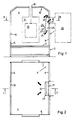
- the powder spray booth (1) shown in the drawing stands on a base frame (2) and has a booth floor (3) over which a spray space (4) is formed, which is formed by two side walls (5,6) and end walls (7,8 ), which are referred to as a peripheral wall (9), and is delimited by a cabin roof (10).
- Workpieces (15) hanging on a transport device can be continuously driven through the cabin through a longitudinal slot (13) provided on the cabin roof, from which through openings (14) are formed in the end walls (7, 8).
- a spray opening (16) is formed in the side wall (5) and an outlet opening (17) is formed in the side wall (6).
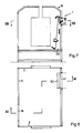
- These openings (16, 17) are at least shown opposite one another in FIG. 2, but in the case of elongated cabins they are often offset from one another in the longitudinal direction of the cabin, as shown in FIG. 8, or several are offset toward the end walls (7, 8)
- manually or automatically guided spraying devices mostly in the form of powder spray guns, can also be used, but other devices which introduce the powder into the cabin air or another gas used there.
- devices are common to favor the precipitation of the powder on the workpiece, in particular the different electrostatic charging of the workpiece and powder, which is also assumed here.
- a line (18) leads from the outlet opening (17) to a powder separator (19).
- This is usually a filter unit, but can also be, for example, a cyclone separator or any other suitable separating device that may be attached to the cabin. The only important thing is that by
- Vacuum on or in the separator generates a suction air flow through the outlet opening (17) so that an air or gas flow through the remaining cabin openings into the spray chamber (4) and around the workpiece (15) is maintained.
- a separate outlet line (18) is therefore not necessary.
- the main flow enters through the spray opening (16), where the flow velocity of the carrier medium is usually increased by means of one or more powder spray guns for the powder.
- Spray opening and outlet opening according to Fig. 8 brings additional swirling.
- the proportion of the spray powder deposited on the cabin floor (3) in the total amount of powder is, however, directly dependent on the degree of turbulence on the way into the spray room. The amount of precipitation at the spray opening is greatest.
- a diaphragm (22) is attached within the spray chamber (4) at a distance from the side wall (6) or the peripheral wall (9), which here has the shape of a rectangular plate, with its upper edge on a hinge (23) is suspended. It can be pivoted in accordance with the double arrow (24) and can be determined by any inhibition in a certain inclination position.
- the lower edge (27) of the screen is generally slightly inclined towards the interior of the spray chamber, so that there the inlet gap (25) is larger than in the remaining edge area of the screen. The greatest amount of air is also introduced there and from the area of the cabin floor (3) the largest part of the powder particles deposited there.
- the swivel setting on the joint (23) allows this distribution and thus the respective situation in a spray room to be adapted.
- the raw gas drawn off from the spray chamber (4) reaches the entire edge or a larger part of the edge of the diaphragm (27) into a flat calming space (28) upstream of the outlet opening (17).
- the individual flows can equalize, so that the turbulence is reduced so far and at least approximately a laminar flow is achieved, which does not or only slightly changes the flow behavior even under the influence of the suction effect of the separator (19).
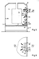
- a somewhat inclined tubular suction shaft (31) is led up from its curved suction end (32) resting on the cabin floor (3) here to the outlet opening (17). It is provided on at least one side with a row of suction openings (33) one above the other, which are formed by wedge-shaped guide flaps (34).
- a pronounced main sweep flow indicated by the arrows (35) is generated directly on the cabin floor (3) and deflected smoothly at the lower and at the upper end of the suction shaft (31).
- the suction shaft is close to the side wall (6) and thus approximately perpendicular, but like the suction shaft (31) according to FIG. 3 it can be pivoted about the joint (23). It ends at the bottom in a suction shoe (36), the cross section of which increases towards the cabin floor (3), and forms a suction end (321) separated from it only by a suction gap (37).
- Suction openings (331) are provided in the front walls and a vertical slot (38) with widened gaps (39) is formed towards the side wall (6). In this way, raw gas can be sucked in practically from the entire vicinity of the shaft, which reduces and evenens the flow velocities. For special purposes, however, extraction shafts without side extraction openings can also be used.
- FIG. 7 A comparable embodiment is shown in Fig. 7, where the arrow (42) only shows a front suction opening.
- the spray opening (16) and the suction shaft (322) are almost diagonally opposite.
Landscapes
- Details Or Accessories Of Spraying Plant Or Apparatus (AREA)
- Prevention Of Fouling (AREA)
- Glanulating (AREA)
Priority Applications (1)
| Application Number | Priority Date | Filing Date | Title |
|---|---|---|---|
| AT90102538T ATE84246T1 (de) | 1989-02-18 | 1990-02-09 | Pulverspruehkabine mit einer leitvorrichtung fuer rohgas in eine abscheider-saugstroemung. |
Applications Claiming Priority (2)
| Application Number | Priority Date | Filing Date | Title |
|---|---|---|---|
| DE3905057 | 1989-02-18 | ||
| DE3905057A DE3905057A1 (de) | 1989-02-18 | 1989-02-18 | Pulverspruehkabine mit einer leitvorrichtung fuer rohgas in eine abscheider-saugstroemung |
Publications (2)
| Publication Number | Publication Date |
|---|---|
| EP0384236A1 true EP0384236A1 (fr) | 1990-08-29 |
| EP0384236B1 EP0384236B1 (fr) | 1993-01-07 |
Family
ID=6374447
Family Applications (1)
| Application Number | Title | Priority Date | Filing Date |
|---|---|---|---|
| EP90102538A Expired - Lifetime EP0384236B1 (fr) | 1989-02-18 | 1990-02-09 | Cabine d'atomisation à poudre avec dispositif pour guider le gaz brut dans un courant aspirateur d'un séparateur |
Country Status (4)
| Country | Link |
|---|---|
| US (1) | US5056460A (fr) |
| EP (1) | EP0384236B1 (fr) |
| AT (1) | ATE84246T1 (fr) |
| DE (2) | DE3905057A1 (fr) |
Cited By (3)
| Publication number | Priority date | Publication date | Assignee | Title |
|---|---|---|---|---|
| WO1995010365A1 (fr) * | 1993-10-14 | 1995-04-20 | Nordson Corporation | Module de recuperation de poudre |
| DE19644360A1 (de) * | 1996-10-25 | 1998-04-30 | Pbs Pulverbeschichtungs Und Sp | Farbsprühkabine |
| WO2021233984A1 (fr) * | 2020-05-20 | 2021-11-25 | Gema Switzerland Gmbh | Pièce principale pour une cellule de revêtement d'une installation de revêtement |
Families Citing this family (23)
| Publication number | Priority date | Publication date | Assignee | Title |
|---|---|---|---|---|
| US5169448A (en) * | 1991-01-15 | 1992-12-08 | Northern Telecom Limited | Tackiness tester |
| US5141767A (en) * | 1991-01-15 | 1992-08-25 | Northern Telecom Limited | Method for providing a measure of tackiness of a body surface |
| US5851248A (en) * | 1992-10-02 | 1998-12-22 | Nordson Corporation | Filter cartridge assembly for powder coating booth and collection system |
| DE4413349C2 (de) * | 1994-04-18 | 1998-02-19 | Boellhoff Verfahrenstech | Absaugvorrichtung für Pulver oder Staub, die an eine Pulverbeschichtungskabine anschließbar ist |
| US5599369A (en) * | 1994-04-29 | 1997-02-04 | Owens-Brockway Glass Container Inc. | Hood for metal-oxide vapor coating glass containers |
| DE4446089C2 (de) * | 1994-12-22 | 2001-05-10 | Eisenmann Kg Maschbau | Verfahren zur Pulverbeschichtung und Lackieranlage zur Durchführung des Verfahrens |
| DE19616220A1 (de) * | 1996-04-23 | 1997-10-30 | Erich Kraemer | Pulverbeschichtungskabine |
| US6007318A (en) | 1996-12-20 | 1999-12-28 | Z Corporation | Method and apparatus for prototyping a three-dimensional object |
| US7037382B2 (en) * | 1996-12-20 | 2006-05-02 | Z Corporation | Three-dimensional printer |
| JPH11179248A (ja) * | 1997-12-25 | 1999-07-06 | Nippon Parkerizing Co Ltd | 粉体塗装装置及び方法 |
| US6068702A (en) * | 1998-03-13 | 2000-05-30 | Nordson Corporation | Powder coating apparatus for use in multiple powder coating techniques |
| DE19900243A1 (de) * | 1999-01-07 | 2000-08-10 | Basf Coatings Ag | Spritzstand mit Absaugvorrichtungen |
| DE19936782A1 (de) * | 1999-08-09 | 2001-03-15 | Gescha Absauganlagen Vertriebs | Absauggerät zum Absaugen verunreinigter Luft |
| IT1316191B1 (it) * | 2000-01-25 | 2003-04-03 | Wagner Itep S P A | Cabina di verniciatura con sistema di recupero delle polverimigliorato. |
| DE10005656C2 (de) | 2000-02-09 | 2003-01-30 | Wagner Internat Ag Altstaetten | Pulverbeschichtungsanlage mit Rückgewinnungs- und Filtereinheit |
| US6663693B2 (en) * | 2001-10-05 | 2003-12-16 | Nordson Corporation | Duct cleaning for powder spray system |
| US20040084814A1 (en) * | 2002-10-31 | 2004-05-06 | Boyd Melissa D. | Powder removal system for three-dimensional object fabricator |
| US20070095279A1 (en) * | 2005-10-27 | 2007-05-03 | Langeman Gary D | Spray enclosure |
| DE202005019313U1 (de) * | 2005-12-08 | 2006-02-23 | J. Wagner Ag | Pulverbeschichtungskabine |
| DE202011051599U1 (de) * | 2011-10-11 | 2011-11-04 | Alois Gans | Pulverbeschichtungsanlage |
| GB201806201D0 (en) * | 2018-04-16 | 2018-05-30 | Carlisle Fluid Tech Inc | Coating Booth |
| US11084208B2 (en) | 2018-10-17 | 2021-08-10 | General Electric Company | Additive manufacturing systems and methods including louvered particulate containment wall |
| CN121057841A (zh) * | 2023-04-12 | 2025-12-02 | 阿科玛股份有限公司 | 用于涂覆玻璃容器的涂覆罩的可调导流板 |
Citations (5)
| Publication number | Priority date | Publication date | Assignee | Title |
|---|---|---|---|---|
| GB1315671A (en) * | 1969-01-31 | 1973-05-02 | Berridge Eng Ltd | Method and apparatus for use in applying particulate material to articles for the purpose of coating the same |
| US4245551A (en) * | 1979-03-05 | 1981-01-20 | Nordson Corporation | Coating booth for electrostatic application of pulverized materials |
| US4354451A (en) * | 1980-01-30 | 1982-10-19 | Esb Elektrostatische Spruh- Und Beschichtungsanlagen G.F. Vohringer Gmbh | Device for spray-coating a workpiece with powder particles |
| DE3229717A1 (de) * | 1982-08-10 | 1984-02-16 | ESB Elektrostatische Sprüh- und Beschichtungsanlagen G.F. Vöhringer GmbH, 7758 Meersburg | Pulverspruehkabine |
| ATE10445T1 (de) * | 1980-03-11 | 1984-12-15 | Protectaire Systems Company | Spritzkabine und verfahren zu ihrer bedienung. |
Family Cites Families (14)
| Publication number | Priority date | Publication date | Assignee | Title |
|---|---|---|---|---|
| DE262998C (fr) * | ||||
| DE595602C (de) * | 1932-02-24 | 1934-04-19 | Carl Hofmann Fa | Ringbank fuer Ringspinn- und Ringzwirnmaschinen |
| US2583489A (en) * | 1946-10-09 | 1952-01-22 | Benjamin Electric Mfg Co | Spray booth |
| AT167839B (de) * | 1949-06-21 | 1951-03-10 | Waagner Biro Ag | Filteranlage für Gase |
| DE1726283U (de) * | 1955-12-09 | 1956-07-12 | Elmar Dipl Kfm D Messerschmitt | Absaugvorrichtung, insbesondere fuer trockenhorden. |
| CH412651A (de) * | 1963-10-10 | 1966-04-30 | Froehlich Albert | Mobile Spritzkabine |
| GB1150782A (en) * | 1965-10-07 | 1969-04-30 | Svenska Flaektfabriken Ab | Spray Painting Booth |
| CH475800A (de) * | 1967-04-24 | 1969-07-31 | Froehlich Albert | Mobile Spritzkabine |
| CA1164787A (fr) * | 1980-03-11 | 1984-04-03 | Stanley C. Napadow | Cabine de pistolage, et mode d'emploi connexe |
| US4303417A (en) * | 1980-10-03 | 1981-12-01 | George Koch Sons, Inc. | Spray booth with reconditioning filter system |
| DE3131565C2 (de) * | 1981-08-10 | 1984-12-13 | Ransburg-Gema AG, St.Gallen | Kabine zum Sprühbeschichten von Gegenständen mit Pulver |
| DE3500005A1 (de) * | 1985-01-02 | 1986-07-10 | ESB Elektrostatische Sprüh- und Beschichtungsanlagen G.F. Vöhringer GmbH, 7758 Meersburg | Beschichtungskabine zum ueberziehen der oberflaeche von werkstuecken mit beschichtungspulver |
| DE8703220U1 (de) * | 1987-03-04 | 1987-07-02 | Fa. Paul Rippert, 4836 Herzebrock | Vorrichtung zum Abschirmen von Arbeitsplätzen mit Staubanfall |
| DE8715970U1 (de) * | 1987-12-03 | 1988-02-11 | Schaber, Gerhard, 7270 Nagold | Vorrichtung zum Absaugen von verunreinigter Luft |
-
1989
- 1989-02-18 DE DE3905057A patent/DE3905057A1/de not_active Withdrawn
-
1990
- 1990-02-09 DE DE9090102538T patent/DE59000711D1/de not_active Expired - Fee Related
- 1990-02-09 EP EP90102538A patent/EP0384236B1/fr not_active Expired - Lifetime
- 1990-02-09 AT AT90102538T patent/ATE84246T1/de not_active IP Right Cessation
- 1990-02-20 US US07/483,209 patent/US5056460A/en not_active Expired - Fee Related
Patent Citations (5)
| Publication number | Priority date | Publication date | Assignee | Title |
|---|---|---|---|---|
| GB1315671A (en) * | 1969-01-31 | 1973-05-02 | Berridge Eng Ltd | Method and apparatus for use in applying particulate material to articles for the purpose of coating the same |
| US4245551A (en) * | 1979-03-05 | 1981-01-20 | Nordson Corporation | Coating booth for electrostatic application of pulverized materials |
| US4354451A (en) * | 1980-01-30 | 1982-10-19 | Esb Elektrostatische Spruh- Und Beschichtungsanlagen G.F. Vohringer Gmbh | Device for spray-coating a workpiece with powder particles |
| ATE10445T1 (de) * | 1980-03-11 | 1984-12-15 | Protectaire Systems Company | Spritzkabine und verfahren zu ihrer bedienung. |
| DE3229717A1 (de) * | 1982-08-10 | 1984-02-16 | ESB Elektrostatische Sprüh- und Beschichtungsanlagen G.F. Vöhringer GmbH, 7758 Meersburg | Pulverspruehkabine |
Cited By (5)
| Publication number | Priority date | Publication date | Assignee | Title |
|---|---|---|---|---|
| WO1995010365A1 (fr) * | 1993-10-14 | 1995-04-20 | Nordson Corporation | Module de recuperation de poudre |
| DE19644360A1 (de) * | 1996-10-25 | 1998-04-30 | Pbs Pulverbeschichtungs Und Sp | Farbsprühkabine |
| DE19644360C2 (de) * | 1996-10-25 | 2002-01-03 | Pbs Pulverbeschichtungs Und Sp | Farbsprühkabine mit Düsen zur Erzeugung horizontal gerichteter Querluftströme |
| WO2021233984A1 (fr) * | 2020-05-20 | 2021-11-25 | Gema Switzerland Gmbh | Pièce principale pour une cellule de revêtement d'une installation de revêtement |
| CN115666795A (zh) * | 2020-05-20 | 2023-01-31 | 瑞士金马有限公司 | 用于涂敷设施的涂敷单元的基体 |
Also Published As
| Publication number | Publication date |
|---|---|
| DE59000711D1 (de) | 1993-02-18 |
| US5056460A (en) | 1991-10-15 |
| DE3905057A1 (de) | 1990-08-23 |
| ATE84246T1 (de) | 1993-01-15 |
| EP0384236B1 (fr) | 1993-01-07 |
Similar Documents
| Publication | Publication Date | Title |
|---|---|---|
| EP0384236B1 (fr) | Cabine d'atomisation à poudre avec dispositif pour guider le gaz brut dans un courant aspirateur d'un séparateur | |
| EP0100932B1 (fr) | Cabine de pulvérisation de poudre | |
| EP0044310B1 (fr) | Installation de revetement de pieces d'oeuvre par poudre comportant une cabine pour recevoir temporairement la piece d'oeuvre | |
| DE3109154C2 (de) | Vorrichtung zum Abscheiden von Fremdkörpern, insbesondere Schwerteilen wie Metall-, Holz- und Pappteilen o.dgl. aus Baumwollfaserflocken | |
| DE202006021158U1 (de) | Vorrichtung zum Abtrennen von Nasslack-Overspray | |
| DE3912958C2 (fr) | ||
| DE1802161A1 (de) | Verfahren und Vorrichtung zum Klassieren und Abgeben von Material | |
| DE3012877A1 (de) | Anlage zum pulverbeschichten von werkstuecken | |
| DE2161198C3 (de) | Vorrichtung zur Reinigung der Abluft einer Spritzkabine | |
| DE3626053C2 (fr) | ||
| CH687593A5 (de) | Pulver-Spruehbeschichtungsvorrichtung. | |
| DE19824802A1 (de) | Pulverförder-Injektor | |
| CH626817A5 (fr) | ||
| DE1913708C3 (de) | Verfahren und Vorrichtung zum Trennen von koernigem Gut | |
| DE69511772T2 (de) | Zufuhrvorrichtung für einen Scheibenfilter | |
| DE2224519B2 (de) | Ein- oder mehrstufiger Wäscher | |
| DE1421310A1 (de) | Nassstaubabscheider | |
| DE3149253C2 (fr) | ||
| CH688589A5 (de) | Vorrichtung an einer Karde zum Abnehmen und Zusammenfassen eines aus einem Lieferwerk der Karde austretenden Faserflors. | |
| EP0281520A2 (fr) | Elément de séparation pour délimiter la largeur d'un rideau de coulée | |
| DE1269594B (de) | Vorrichtung zum Entfernen von wasserunloeslichen Stoffen aus Luft | |
| DE202010004167U1 (de) | Fließbettsichter | |
| DE102005050199A1 (de) | Vorrichtung zum Bestäuben von Produkten, insbesondere Druckprodukten | |
| DE10352525B9 (de) | Zyklonsichter | |
| DE2031081A1 (de) | Spritzkasten |
Legal Events
| Date | Code | Title | Description |
|---|---|---|---|
| PUAI | Public reference made under article 153(3) epc to a published international application that has entered the european phase |
Free format text: ORIGINAL CODE: 0009012 |
|
| AK | Designated contracting states |
Kind code of ref document: A1 Designated state(s): AT CH DE FR GB IT LI SE |
|
| 17P | Request for examination filed |
Effective date: 19900807 |
|
| 17Q | First examination report despatched |
Effective date: 19920514 |
|
| GRAA | (expected) grant |
Free format text: ORIGINAL CODE: 0009210 |
|
| AK | Designated contracting states |
Kind code of ref document: B1 Designated state(s): AT CH DE FR GB IT LI SE |
|
| PG25 | Lapsed in a contracting state [announced via postgrant information from national office to epo] |
Ref country code: SE Effective date: 19930107 |
|
| REF | Corresponds to: |
Ref document number: 84246 Country of ref document: AT Date of ref document: 19930115 Kind code of ref document: T |
|
| ITF | It: translation for a ep patent filed | ||
| REF | Corresponds to: |
Ref document number: 59000711 Country of ref document: DE Date of ref document: 19930218 |
|
| ET | Fr: translation filed | ||
| GBT | Gb: translation of ep patent filed (gb section 77(6)(a)/1977) |
Effective date: 19930318 |
|
| PLBE | No opposition filed within time limit |
Free format text: ORIGINAL CODE: 0009261 |
|
| STAA | Information on the status of an ep patent application or granted ep patent |
Free format text: STATUS: NO OPPOSITION FILED WITHIN TIME LIMIT |
|
| 26N | No opposition filed | ||
| PGFP | Annual fee paid to national office [announced via postgrant information from national office to epo] |
Ref country code: GB Payment date: 20001212 Year of fee payment: 12 |
|
| PGFP | Annual fee paid to national office [announced via postgrant information from national office to epo] |
Ref country code: FR Payment date: 20010221 Year of fee payment: 12 |
|
| PGFP | Annual fee paid to national office [announced via postgrant information from national office to epo] |
Ref country code: AT Payment date: 20010226 Year of fee payment: 12 |
|
| PGFP | Annual fee paid to national office [announced via postgrant information from national office to epo] |
Ref country code: CH Payment date: 20010227 Year of fee payment: 12 |
|
| PGFP | Annual fee paid to national office [announced via postgrant information from national office to epo] |
Ref country code: DE Payment date: 20010426 Year of fee payment: 12 |
|
| REG | Reference to a national code |
Ref country code: GB Ref legal event code: IF02 |
|
| PG25 | Lapsed in a contracting state [announced via postgrant information from national office to epo] |
Ref country code: GB Free format text: LAPSE BECAUSE OF NON-PAYMENT OF DUE FEES Effective date: 20020209 Ref country code: AT Free format text: LAPSE BECAUSE OF NON-PAYMENT OF DUE FEES Effective date: 20020209 |
|
| PG25 | Lapsed in a contracting state [announced via postgrant information from national office to epo] |
Ref country code: LI Free format text: LAPSE BECAUSE OF NON-PAYMENT OF DUE FEES Effective date: 20020228 Ref country code: CH Free format text: LAPSE BECAUSE OF NON-PAYMENT OF DUE FEES Effective date: 20020228 |
|
| PG25 | Lapsed in a contracting state [announced via postgrant information from national office to epo] |
Ref country code: DE Free format text: LAPSE BECAUSE OF NON-PAYMENT OF DUE FEES Effective date: 20020903 |
|
| GBPC | Gb: european patent ceased through non-payment of renewal fee |
Effective date: 20020209 |
|
| REG | Reference to a national code |
Ref country code: CH Ref legal event code: PL |
|
| PG25 | Lapsed in a contracting state [announced via postgrant information from national office to epo] |
Ref country code: FR Free format text: LAPSE BECAUSE OF NON-PAYMENT OF DUE FEES Effective date: 20021031 |
|
| REG | Reference to a national code |
Ref country code: FR Ref legal event code: ST |
|
| PG25 | Lapsed in a contracting state [announced via postgrant information from national office to epo] |
Ref country code: IT Free format text: LAPSE BECAUSE OF NON-PAYMENT OF DUE FEES;WARNING: LAPSES OF ITALIAN PATENTS WITH EFFECTIVE DATE BEFORE 2007 MAY HAVE OCCURRED AT ANY TIME BEFORE 2007. THE CORRECT EFFECTIVE DATE MAY BE DIFFERENT FROM THE ONE RECORDED. Effective date: 20050209 |