EP0384298A2 - Vorrichtung zur Gasanalyse - Google Patents
Vorrichtung zur Gasanalyse Download PDFInfo
- Publication number
- EP0384298A2 EP0384298A2 EP90102968A EP90102968A EP0384298A2 EP 0384298 A2 EP0384298 A2 EP 0384298A2 EP 90102968 A EP90102968 A EP 90102968A EP 90102968 A EP90102968 A EP 90102968A EP 0384298 A2 EP0384298 A2 EP 0384298A2
- Authority
- EP
- European Patent Office
- Prior art keywords
- output
- pass filter
- photo diode
- band pass
- gas analyzer
- Prior art date
- Legal status (The legal status is an assumption and is not a legal conclusion. Google has not performed a legal analysis and makes no representation as to the accuracy of the status listed.)
- Granted
Links
Images


Classifications
-
- G—PHYSICS
- G01—MEASURING; TESTING
- G01N—INVESTIGATING OR ANALYSING MATERIALS BY DETERMINING THEIR CHEMICAL OR PHYSICAL PROPERTIES
- G01N21/00—Investigating or analysing materials by the use of optical means, i.e. using sub-millimetre waves, infrared, visible or ultraviolet light
- G01N21/75—Systems in which material is subjected to a chemical reaction, the progress or the result of the reaction being investigated
- G01N21/76—Chemiluminescence; Bioluminescence
- G01N21/766—Chemiluminescence; Bioluminescence of gases
Definitions
- the present invention relates to a gas analyzer, for example to a chemical luminescence analyzer (hereinafter referred to as CLA).
- CLA chemical luminescence analyzer
- a CLA is, by far, inexpensiver than a photomultiplier tube, superior in efficiency at normal temperature, and capable of being small-sized, so that a photo diode has been used as a light-measuring element in many cases.
- the gas analyzer according to the above described publication has exhibited disadvantages in that if the output signals of said two photo diodes are reduced, stationary noises are increased, so that it is impossible to detect the spike noises in an accuracy required for the analyzer.
- Horiba, Ltd. has proposed in the Japanese Utility Model Application Laid-Open No. Hei 1-14282o that two photo diodes are disposed for a sample to be measured in parallel to each other so that a total sum of outputs of both photo diodes may be held when a difference occurs between both photo diodes in output.
- the present invention has been achieved paying attention to the above described matters and it is an object of the present invention to provide a gas analyzer capable of eliminating the influences through the spike noises incidental to the photo diode and remarkably improving the S/N ratio thereof to achieve a highly accurate measurement in spite of the simple and intensive construction.
- one photo diode is used as a detecting sensor, an output of said photo diode being supplied to a band pass filter and a high pass filter connected in parallel to each other, respectively, so that when an output of said high pass filter is equal or greater than a set value, an output of said band pass filter is sample held.
- one photo diode is used as a detecting sensor, an output of said photo diode being supplied to band pass filters connected with each other in parallel and having frequency characteristics different to each other, and the respective outputs of said band pass filters being leveled followed by taking a difference between the leveled outputs.
- the output of the photo diode is supplied to the band pass filter and the high pass filter, respectively.
- the output of the band pass filter is taken in as a datum as it is.
- the sample hold is carried out on the basis of the output from the high pass filter,thereby removing the spike noises from the output of the band pass filter.
- the output of the photo diode is supplied into two band pass filters having frequency characteristics different to each other.
- the noise ingredients in the outputs of the respective band pass filters are compensated among themselves, whereby removing the spike noises
- Fig.1 shows an example of a construction of a chopping type CLA according to the first preferred embodiment of the present invention.
- reference numeral 1 designates a reaction cell adapted to receive, for example, a sample gas containing a NO gas to be measured and an ozone gas.
- Reference numeral 2 designates a photo diode installed in front of a cell window (not shown) of the reaction cell 1 for detecting light produced by a reaction between said ozone gas and said NO gas.
- Said photo diode 2 is, for example, a silicon diode.
- Reference numeral 3 designates a preamplifier for suitably amplifying an output of said photo diode 2 (this output is proportional to a concentration of the NO gas).
- Reference numerals 4, 5 designate a band pass filter (hereinafter referred to as BPF) and a high pass filter (hereinafter referred to as HPF) disposed in parallel to each other on an output side of said preamplifier 3, respectively.
- a sample and hold circuit 8 is disposed on an output side of the BPF 4 through a rectifier circuit 6 and a leveling circuit 7, which are connected in series to each other.
- Reference numeral 9 designates an output terminal of said and sample hold circuit 8.
- a comparator 10 for comparing an output F of said HPF 5 with a comparator level R to supply an appointed comparator output G when said output F is larger than said comparator level R and a one-shot generating circuit 11 receiving said comparator output G to supply an appointed sample and hold instruction H are disposed on an output side of the HPF 5.
- Reference numeral 12 designates a standard power source providing said comparator level R.
- Said preamplifier output B is supplied to the BPF 4 and the HPF 5, respectively.
- An output C as shown in Fig. 3 (C)
- an output F as shown in Fig. 3(F) is generated by the filter 5.
- the output C of the BPF 4 is rectified in the rectification circuit 6 and then leveled in the leveling circuit. After that the output from the leveling circuit 7 is supplied to the sample and hold circuit 8.
- Figs. 3(D), (E) show a rectification circult output D and a leveling circuit E, respectively.
- the output F of the HPF 5 is supplied to the comparator 10 to be compared with the comparator level R. At this time, when said output F is smaller than the comparator level R, no output is generated by said comparator 10. Accordingly, the output from the BPF 4, which has been leveled in the above described manner, is continuously taken into the sample and hold circuit 8. However, when the spike noises (sp) are contained in said output F and this output F is larger than the comparator level R, the comparator output G, as shown in Fig. 3(G) is outputted from the comparator 10. This output G is supplied to the one-shot generating circuit 11 to generate the output H, as shown in Fig.
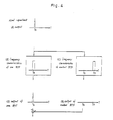
- Fig. 2 shows an example of the construction of a chopping type CLA according to the second preferred embodiment of the present invention.
- reference numerals 13, 14 designate band pass filters (BPFs) having different frequency characteristics disposed in parallel to each other on an output side of a photo diode 2
- reference numerals 15, 16 designate circuits for rectifying and leveling outputs of said BPFs 13, 14,
- reference numeral 17 designates a differential amplifier as a subtraction circuit for calculating a difference between outputs of said rectifying and leveling circuits 15, 16, and reference numeral 18 designates an output terminal of said differential amplifier 17.
- BPFs band pass filters
- the signal ingredient output has a frequency characteristic, as shown in Fig. 4(A) and the BPFs 13, 14 have frequency characteristics, as shown in Fig. 4(B), (C), respectively.
- Said signal ingredient output is supplied to the BPF 13 and BPF 14, respectively, to obtain an output as shown in Fig. 4(A) merely from one BPF 13 but not to obtain an output from the other BPF 14, as indicated in Fig. 4(D), (E), so that a signal ingredient output similar to that shown in Fig. 4(A) is obtained from the differential amplifier 17.
- noise ingredients provided in the output of the preamplifier 3
- said noise ingredients have an output as shown in Fig. 5(A).
- the BPFs 13, 14 have the frequency characteristics as shown in Fig. 5(B) and Fig. 5(C), respectively, outputs having different frequencies are obtained from the respective BPFs 13,14, as shown in Fig. 4(D), (E),whereby they are treated in the rectifying and leveling circuits 15, 16 so that a difference between them may be neglected followed by being compensated with each other in the differential amplifier 17.
- the present invention is not limited by the above described two preferred embodiments, but it can be practiced in the form of various kinds of modification.
- the output C of the BPF 4 may be subjected to the rectifying treatment and the leveling treatment at the same time.
- the present invention can be applied also to CLAs other than the chopping type CLA and gas analyzers other than CLAs. That is to say, in the case where there is a sufficient difference (rise time) between the signal resulting from the change of the gas concentration and the change of the spike noises, it is possible to omit the BPF 4, the rectifying circuit 6 and the leveling circuit 7 in Fig. 1.
- the signal treatment may be conducivelyted by means of a CPU. That is to say, for example, in the first preferred embodiment the output of the preamplifier 3 is supplied to the CPU where the output is subjected to the appointed treatment. In this case, the sample and hold treatment is not conducted but an influence by the spike noises can be acted to subtract it. In such case, a smooth output wave form can be obtained even though the gas concentration is changed.
Landscapes
- Physics & Mathematics (AREA)
- Chemical & Material Sciences (AREA)
- Biochemistry (AREA)
- General Health & Medical Sciences (AREA)
- Plasma & Fusion (AREA)
- Health & Medical Sciences (AREA)
- Life Sciences & Earth Sciences (AREA)
- Analytical Chemistry (AREA)
- Engineering & Computer Science (AREA)
- Chemical Kinetics & Catalysis (AREA)
- General Physics & Mathematics (AREA)
- Immunology (AREA)
- Pathology (AREA)
- Investigating Or Analysing Materials By Optical Means (AREA)
- Photometry And Measurement Of Optical Pulse Characteristics (AREA)
- Sampling And Sample Adjustment (AREA)
Applications Claiming Priority (2)
| Application Number | Priority Date | Filing Date | Title |
|---|---|---|---|
| JP20666/89U | 1989-02-23 | ||
| JP1989020666U JPH0520993Y2 (de) | 1989-02-23 | 1989-02-23 |
Publications (3)
| Publication Number | Publication Date |
|---|---|
| EP0384298A2 true EP0384298A2 (de) | 1990-08-29 |
| EP0384298A3 EP0384298A3 (de) | 1991-10-02 |
| EP0384298B1 EP0384298B1 (de) | 1994-07-20 |
Family
ID=12033523
Family Applications (1)
| Application Number | Title | Priority Date | Filing Date |
|---|---|---|---|
| EP90102968A Expired - Lifetime EP0384298B1 (de) | 1989-02-23 | 1990-02-15 | Vorrichtung zur Gasanalyse |
Country Status (4)
| Country | Link |
|---|---|
| EP (1) | EP0384298B1 (de) |
| JP (1) | JPH0520993Y2 (de) |
| AT (1) | ATE108903T1 (de) |
| DE (1) | DE69010709T2 (de) |
Cited By (1)
| Publication number | Priority date | Publication date | Assignee | Title |
|---|---|---|---|---|
| US6404488B1 (en) | 1999-09-06 | 2002-06-11 | University Of Liege | Photometer |
Family Cites Families (2)
| Publication number | Priority date | Publication date | Assignee | Title |
|---|---|---|---|---|
| US4220412A (en) * | 1978-10-25 | 1980-09-02 | Eastman Kodak Company | Illuminant discrimination apparatus and method |
| US4657744A (en) * | 1985-07-02 | 1987-04-14 | Sensors, Inc. | Chemiluminescent gas analyzer for measuring the oxides of nitrogen |
-
1989
- 1989-02-23 JP JP1989020666U patent/JPH0520993Y2/ja not_active Expired - Lifetime
-
1990
- 1990-02-15 EP EP90102968A patent/EP0384298B1/de not_active Expired - Lifetime
- 1990-02-15 AT AT90102968T patent/ATE108903T1/de not_active IP Right Cessation
- 1990-02-15 DE DE69010709T patent/DE69010709T2/de not_active Expired - Fee Related
Cited By (1)
| Publication number | Priority date | Publication date | Assignee | Title |
|---|---|---|---|---|
| US6404488B1 (en) | 1999-09-06 | 2002-06-11 | University Of Liege | Photometer |
Also Published As
| Publication number | Publication date |
|---|---|
| JPH0520993Y2 (de) | 1993-05-31 |
| ATE108903T1 (de) | 1994-08-15 |
| EP0384298B1 (de) | 1994-07-20 |
| DE69010709D1 (de) | 1994-08-25 |
| EP0384298A3 (de) | 1991-10-02 |
| DE69010709T2 (de) | 1995-02-23 |
| JPH02110837U (de) | 1990-09-05 |
Similar Documents
| Publication | Publication Date | Title |
|---|---|---|
| US4773422A (en) | Single channel pulse oximeter | |
| USRE33643E (en) | Pulse oximeter with circuit leakage and ambient light compensation | |
| US3967933A (en) | Dual channel nitrogen oxides analyzer | |
| US5463467A (en) | Light source pulsed with irregular pulse sequence in analog photometric signal evaluation for a test carrier analysis system | |
| PL1549932T3 (pl) | Sposób wykrywania gazu i urządzenie do wykrywania gazu | |
| EP0151613B1 (de) | Atemanalysevorrichtung | |
| US7630084B2 (en) | System and method for acquiring and evaluating optical signals | |
| EP0384298A2 (de) | Vorrichtung zur Gasanalyse | |
| US4669872A (en) | Temperature measuring device | |
| JPS61194332A (ja) | ガス濃度を測定する方法およびこの方法を実施するための装置 | |
| JPH01214723A (ja) | 分光蛍光光度計 | |
| JPS59176649A (ja) | 粒子分析装置 | |
| JP2000074968A (ja) | 信号検出装置 | |
| JP2934653B2 (ja) | 自動分析装置 | |
| JPS59182341A (ja) | 試料発光の異方性測定装置 | |
| US6411380B1 (en) | Detection device for a spectrophotometer | |
| JP3177379B2 (ja) | 油分濃度計 | |
| JPS6154488A (ja) | ライブタイム測定方法 | |
| JP3324186B2 (ja) | 発光分光分析装置 | |
| JPH01156646A (ja) | 蛍光x線分析方法 | |
| US4171912A (en) | Element analyzer exploiting a magneto-optic effect | |
| JPH02242140A (ja) | ブレイクダウン分光分析方法及び装置 | |
| GB1591202A (en) | Absorption spectrometry | |
| JP2569500B2 (ja) | X線分析計測装置 | |
| RU1782118C (ru) | Абсорбционный способ определения концентрации веществ |
Legal Events
| Date | Code | Title | Description |
|---|---|---|---|
| PUAI | Public reference made under article 153(3) epc to a published international application that has entered the european phase |
Free format text: ORIGINAL CODE: 0009012 |
|
| AK | Designated contracting states |
Kind code of ref document: A2 Designated state(s): AT DE |
|
| PUAL | Search report despatched |
Free format text: ORIGINAL CODE: 0009013 |
|
| AK | Designated contracting states |
Kind code of ref document: A3 Designated state(s): AT DE |
|
| 17P | Request for examination filed |
Effective date: 19910920 |
|
| 17Q | First examination report despatched |
Effective date: 19930914 |
|
| GRAA | (expected) grant |
Free format text: ORIGINAL CODE: 0009210 |
|
| AK | Designated contracting states |
Kind code of ref document: B1 Designated state(s): AT DE |
|
| PG25 | Lapsed in a contracting state [announced via postgrant information from national office to epo] |
Ref country code: AT Effective date: 19940720 |
|
| REF | Corresponds to: |
Ref document number: 108903 Country of ref document: AT Date of ref document: 19940815 Kind code of ref document: T |
|
| REF | Corresponds to: |
Ref document number: 69010709 Country of ref document: DE Date of ref document: 19940825 |
|
| PGFP | Annual fee paid to national office [announced via postgrant information from national office to epo] |
Ref country code: DE Payment date: 19950224 Year of fee payment: 6 |
|
| PLBE | No opposition filed within time limit |
Free format text: ORIGINAL CODE: 0009261 |
|
| STAA | Information on the status of an ep patent application or granted ep patent |
Free format text: STATUS: NO OPPOSITION FILED WITHIN TIME LIMIT |
|
| 26N | No opposition filed | ||
| PG25 | Lapsed in a contracting state [announced via postgrant information from national office to epo] |
Ref country code: DE Effective date: 19961101 |