EP0384335B1 - Hydraulische Drehkolbenmaschine - Google Patents
Hydraulische Drehkolbenmaschine Download PDFInfo
- Publication number
- EP0384335B1 EP0384335B1 EP90103107A EP90103107A EP0384335B1 EP 0384335 B1 EP0384335 B1 EP 0384335B1 EP 90103107 A EP90103107 A EP 90103107A EP 90103107 A EP90103107 A EP 90103107A EP 0384335 B1 EP0384335 B1 EP 0384335B1
- Authority
- EP
- European Patent Office
- Prior art keywords
- housing
- rotor
- cam
- vanes
- machine
- Prior art date
- Legal status (The legal status is an assumption and is not a legal conclusion. Google has not performed a legal analysis and makes no representation as to the accuracy of the status listed.)
- Expired
Links
- 239000012530 fluid Substances 0.000 claims description 38
- 230000002093 peripheral effect Effects 0.000 claims description 3
- 238000010586 diagram Methods 0.000 description 2
- 238000010276 construction Methods 0.000 description 1
- 230000007812 deficiency Effects 0.000 description 1
- 238000011161 development Methods 0.000 description 1
- 230000018109 developmental process Effects 0.000 description 1
- 238000007789 sealing Methods 0.000 description 1
- 238000000926 separation method Methods 0.000 description 1
Images

Classifications
-
- F—MECHANICAL ENGINEERING; LIGHTING; HEATING; WEAPONS; BLASTING
- F01—MACHINES OR ENGINES IN GENERAL; ENGINE PLANTS IN GENERAL; STEAM ENGINES
- F01C—ROTARY-PISTON OR OSCILLATING-PISTON MACHINES OR ENGINES
- F01C21/00—Component parts, details or accessories not provided for in groups F01C1/00 - F01C20/00
- F01C21/08—Rotary pistons
- F01C21/0809—Construction of vanes or vane holders
- F01C21/0818—Vane tracking; control therefor
- F01C21/0827—Vane tracking; control therefor by mechanical means
- F01C21/0836—Vane tracking; control therefor by mechanical means comprising guiding means, e.g. cams, rollers
Definitions
- the present invention is directed to rotary hydraulic machines according to the preamble of claim 1.
- Such machines of the sliding-vane type are capable of functioning as hydraulic pumps or motors.
- Rotary hydraulic machines of the subject type generally include a housing, a rotor mounted for rotation within the housing and having a plurality of radially extending peripheral slots, and a plurality of vanes individually slidably mounted in the slots.
- a cam ring surrounds the rotor and has a radially inwardly directed surface forming a vane track and one or more fluid pressure cavities between the cam surface and the rotor. Inlet and outlet passages feed hydraulic fluid to and from the cavities.
- undervane fluid pressure either intermittent or continuous, usually requires the use of valves for feeding the fluid to the undervane chambers prior to the primary machine cavities, and also does not overcome the problem of vane impact against the cam ring surface except where combined with the vane springs.
- So-called inner vane machines have addressed, but not entirely overcome the problems in question.
- cam means are provided within the housing which limit the travel of the vanes inwardly.
- the cams however have profiled surfaces which are equidistant from the profiled surfaces of the vane track surface only in the section situated between the port openings used for the delivery and draining of the working fluid.
- the cam means show flat surfaces so that the separation between the vane track surface and the cam ring surface is non-uniform. Therefore, the clearance between the outer ends of the vanes and the vane track surface is non-uniform so that two distinct disadvantages will follow.
- First in the event of fluctuation or loss of fluid pressure, even minimum sealing is precluded.
- Second when the machine is initially started, the vanes travel for a substantial distance and gather momentum before impact against the vane track surface. This tends to damage the vane tips and the vane track surface.
- the problem to be solved by the present invention is to overcome the deficiencies mentioned above.
- a rotary hydraulic machine that includes facility ensuring that the vanes are continually positioned adjacent to the cam ring surface. Furthermore, frictional wear can be reduced, and the machine is less expensive to manufacturer than are prior art machines of similar type.
- the machine of the present invention can also be used for dividing a single input flow of hydraulic fluid into two or more output flows at a predetermined flow ratio.
- Prior art devices for this purpose have involved relatively complex and expensive specialised structures.
- the present invention contemplates a vane-type rotary hydraulic machine that comprises a housing, a rotor mounted within the housing and having a plurality of radially extending peripheral slots, and a plurality of vanes individually slidably mounted in the rotor slots.
- a cam ring within the housing surrounds the rotor and has a radially inwardly directed surface forming a track for sliding engagement with the vanes, and at least one fluid pressure cavity between the cam ring surface and the rotor. Fluid inlet and outlet passages in the housing are coupled to the pressure cavity.
- a cam mechanism is mounted with the housing in fixed position with respect to the cam ring and has a surface for engaging the radially inner edges of the vanes to position the radially outer vane edges adjacent to the cam ring surface.
- such cam mechanism takes the form of a pair of cam plates having continuous radially orientated surfaces contoured substantially identically to the cam ring surface and spaced radially inwardly therefrom by a distance corresponding to, and preferably slightly greater than, the radial dimension of the rotor vanes.
- the cam plates are carried by the housing and positioned in cylindrical pockets formed in the opposed axially outwardly facing surfaces of the rotor.
- the cam plates uniformly engage the inner edges of the vanes at axially spaced positions.
- fluid pressure chambers are formed in the rotor beneath the vane slots, so that fluid pressure urges the vanes against the cam ring surface during normal operation while lifting the vanes from the cam plate surfaces, thereby eliminating frictional contact and wear between the vanes and the cam plates surfaces.
- the rotor is mounted for free rotation within the housing on a stub shaft completely enclosed by the housing.
- the rotor and cam ring form at least two fluid pressure cavities, preferably two cavities radially symmetrically positioned with respect to the stub shaft.
- the machine thus forms a vane-type flow divider for dividing an input flow of hydraulic fluid under pressure into two output flows at a predetermined flow ratio, specifically at a 1:1 ratio in the preferred embodiment of the invention. Pressure drop between the inlet and outlets is greatly reduced as compared with prior art devices for a similar purpose.
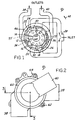
- FIG. 1 schematically illustrates a balanced dual-lobe vane-type rotary hydraulic machine 10 as comprising a rotor 12 rotatable mounted on a shaft 14.
- Rotor 12 has a circular periphery and a circumferential array of radially directed slots 16 in which a corresponding plurality of vanes 18 are radially slidably disposed.
- a cam ring 20 radially surrounds rotor 12, and has a radially inwardly directed cam ring surface 22 that cooperates with rotor 12 and vanes 18 to form a pair of diametrically opposed fluid cavities 24, 26.
- Hydraulic fluid is fed from an inlet 28 to a pair of inlet ports 30, 32 in communication with cavities 24, 26, and the respective cavities also communicate through outlet ports 34, 36 and cross-over passages 35, 37 with the respective fluid outlets 38, 40.
- a chamber 44 is formed in rotor 12 beneath each slot 16 and communicates with ports 30, 32 so that hydraulic fluid pressure urges vanes 18 radially outwardly against surface 22 of cam ring 20.
- machine 10 is of generally conventional construction, and can operate either as a pump, in which rotor 12 is driven in the direction 42 by shaft 14 to pump fluid from low pressure inlet 28 to high pressure outlets 38, 40, or as a motor in which flow of fluid from high pressure inlet 28 to low pressure outlets 38, 40 drives rotor 12 and shaft 14 in the direction 42.
- a cam plate 46 (FIG. 1) is mounted in fixed position relative to cam ring 20 surrounding shaft 14.
- Cam plate 46 has a radially outwardly directed edge surface 48 that engages the radially inner edges of vanes 18 and is substantially identical in contour, yet reduced in size to the opposing surface 22 of cam ring 20.
- Cam plate surface 48 is spaced from cam ring surface 22 by a distance slightly greater than the radial dimension of vanes 18.
- cam plate 46 positions vanes 18 radially adjacent to surface 22 of cam ring 20 at all positions of rotor 12.
- vanes are thus automatically positioned to substantially seal cavities 24, 26 upon initial operation of machine 10, and minimize travel of vanes 18 into radial impact with cam ring surface 22 as fluid pressure is supplied to chambers 44.
- fluid pressure is applied to chambers 44, such fluid pressure urges vanes 18 against cam ring surface 22 so that the vane inner edges are spaced from surface 48 of cam plate 46, thereby reducing sliding friction and wear between the vanes and the cam plate surface.
- rotor 12 is not rotatably coupled to shaft 14, but rather freely rotates with respect thereto, while shaft 14 is completely enclosed within the surrounding housing.
- machine 10 forms a flow divider for dividing input fluid flow at inlet 28 into separate output flows at outlets 38, 40.
- FIGS. 2-4 illustrate a presently preferred embodiment of rotary hydraulic fluid flow divider 10.
- Rotor 12 is freely rotatably mounted on stub shaft 14, which is affixed by a bolt 50 to the cover plate 52 of machine housing 54.
- a washer 56 cooperates with bolt 50 to capture a backup plate 58, with cam ring 20 being sandwiched between backup plate 58 and cover plate 52 to form the rotor cavity.
- Backup plate 58 and cam ring 20 are surrounded by a cup-shaped casing 60 that is affixed by bolts 62 to cover plate 52 to complete housing 54.
- Cover plate 52 and backup plate 58 have axially opposed flat surfaces 53, 59 that face opposing axially outwardly orientated flat surfaces 13, 15 of rotor 12.
- a cam plate 46 is mounted on the rotor-facing surface of each plate 52, 58 and is held thereon by the pins 64. Each cam plate is thus positioned in a substantially cylindrical pocket 74 (Fig. 4) in the opposing rotor surface, with the outer edge surface 48 of each cam plate 48 engaging the opposing inner edges of vanes 18 as previously described.
- Inlet 28 (Figs. 1 and 2) communicates with ports 30, 32 as previously described, and thence through a passage 66 (Fig. 3) to a sealed cavity 68 in backup plate 58.
- a passage 70 extends from cavity 68 to an annular channel 72 on the rotor-opposing face of backup plate 68 to form a hydraulic clamp mechanism to hold backup plate 58 to cam ring 22 to end cover 52.
- Channel 72 is at a radius from the axis of rotation of rotor 12 corresponding to the radial position of fluid chambers 44, and thus feeds fluid at substantially inlet pressure to rotor chambers 44 for urging vanes 18 radially outwardly against cam ring surface 22.
- multi-lobe machines can be provided to make three, four etc. fluid travel cavities.
- inlet and outlet passages are multiplied in accordance with the number of the lobes.
- the input flow then is divided in three or four etc. output flows.
- the cavities normally are equal in size, then also the flows are equal in rate. Yet it is also possible to make the volumes of the cavities different so as to provide a desired predetermined flow ratio between the output flows.
Landscapes
- Engineering & Computer Science (AREA)
- Mechanical Engineering (AREA)
- General Engineering & Computer Science (AREA)
- Rotary Pumps (AREA)
- Hydraulic Motors (AREA)
- Pipeline Systems (AREA)
Claims (5)
ein Gehäuse (54);
ein Rotor (12) ist zur Drehung innerhalb des Gehäuses gelagert und weist eine Mehrzahl von radial sich erstreckenden peripheren Schlitzen (16) auf, die jeweils in einer Uterflügelkammer (44) enden;
eine Mehrzahl von Flügel (18) sind individuell in den Schlitzen (16) verschieblich gelagert und weisen eine vorbestimmte radiale Dimension auf;
ein Nockenring (20) innerhalb des Gehäuses (54) umgibt den Rotor (12) und weist eine radial nach innen gerichtete Flügelbahnoberfläche (22) auf;
mindestens ein Fluidverschiebungsraum (24, 26) ist zwischen der Flügelbahnoberfläche (22) und dem Rotor (12) vorgesehen;
Fluideinlaß- (30, 32) und Auslaß- (34, 36) Einrichtungen sind in dem Gehäuse (54) hydraulisch mit mindestens dem einen Raum (24, 26) verbunden;
eine Nockeneinrichtung (46) ist innerhalb des Gehäuses in fester Stellung innerhalb des Nockenrings (20) montiert und weist eine radial nach außen gerichtete Nockenoberfläche (48) auf, die während des Nichtbetriebes der Maschine oder im Fall von Fluktuation oder Druckverlust wirksam wird, um an den inneren Enden der Flügel (18) anzugreifen und die äußeren radialen Enden benachbart, jedoch mit einem bestimmten Abstand von der Nockenringoberfläche (22) zu positionieren; das Gehäuse (54) weist eine Einrichtung (70, 72) zur Zuführung von unter Druck stehendem Fluid zu den Unterflügelkammern (44) auf, um die Flügel (18) von der Nockenoberfläche (48) anzuheben und die äußeren Enden der Flügel (18) gegen die Flügelbahnoberfläche (22) zu drängen, dadurch gekennzeichnet,
daß die Nockenoberfläche (48) eine kontinuierliche Kontur mit im wesentlichen der gleichen Form wie die Kontur der Flügelbahnoberfläche (22), jedoch reduziert in ihrer Größe, aufweist, so daß die Nockenoberfläche (48) von der Flügelbahnoberfläche (22) um einen im wesentlichen gleichförmigen Abstand augeordnet ist, der ein wenig größer als die radial Abmessung der Flügen (18) ist.
dadurch gekennzeichnet, daß der Rotor (2) eine im wesentlichen ebene Seitenfläche und eine in der Seitenfläche geformte Tasche aufweist,
daß das Gehäuse eine Einrichtung zur Bildung einer im wesentlichen flachen Seite gegenüber der Rotorseitenfläche aufweist und daß die Nockeneinrichtung (46) eine flache Nockenplatte umfaßt, die an dem Gehäuse (54) befestigt und in der Tasche gelegen ist.
dadurch gekennzeichnet, daß der Rotor (12) zwei im wesentlichen ebene Seitenflächen (13, 15) aufweist, die jeweils im wesentlichen kreisförmige, axial nach außen sich öffnende und darin eingeformte Taschen (54) aufweisen,
daß das Gehäuse (54) eine Einrichtung zur Bildung von flachen Seiten (53, 59) aufweist, die diesen Seitenflächen (13, 15) gegenüberstehen und
daß die Nockeneinrichtung (46) zwei im wesentlichen identische Platten aufweist, die an dem Gehäuse (54) befestigt sind und jeweils in einer der Taschen (74) zum hinsichtlich Druck ausgeglichenen Eingriff an den radial inneren Enden der Flügel (18) gelegen sind.
daß der Rotor (12) zur freien Drehung innerhalb des Gehäuses (54) auf einer Stummelachse (14) gelagert ist, die vollständig von dem Gehäuse (54) umschlossen ist, daß die Maschine mindestens zwei Stromverschiebungsräume (24, 26) zwischen der Flügelbahnoberfläche (22) und dem Rotor (12) aufweist, daß eine Einrichtung (28, 30, 32) in dem Gehäuse (54) zur Förderung des Eingangsstromes an unter Druck stehendem hydraulischen Fluid zu den Räumen (24, 26) und eine Einrichtung (34, 36, 38, 40) in dem Gehäuse zur Lieferung mindestens zweier Auslaßströme aus den Räumen (24, 26) vorgesehen sind.
daß der Rotor (12) und der Nockenring (20) so konstruiert und angeordnet sind, daß zwei (24, 26) der Räume radial symmetrisch mit Bezug auf die Stummelachse (14) angeordnet sind.
Applications Claiming Priority (2)
| Application Number | Priority Date | Filing Date | Title |
|---|---|---|---|
| US07/314,884 US4963080A (en) | 1989-02-24 | 1989-02-24 | Rotary hydraulic vane machine with cam-urged fluid-biased vanes |
| US314884 | 1989-02-24 |
Publications (2)
| Publication Number | Publication Date |
|---|---|
| EP0384335A1 EP0384335A1 (de) | 1990-08-29 |
| EP0384335B1 true EP0384335B1 (de) | 1992-07-08 |
Family
ID=23221901
Family Applications (1)
| Application Number | Title | Priority Date | Filing Date |
|---|---|---|---|
| EP90103107A Expired EP0384335B1 (de) | 1989-02-24 | 1990-02-19 | Hydraulische Drehkolbenmaschine |
Country Status (4)
| Country | Link |
|---|---|
| US (1) | US4963080A (de) |
| EP (1) | EP0384335B1 (de) |
| JP (1) | JP3058888B2 (de) |
| DE (1) | DE69000176T2 (de) |
Cited By (1)
| Publication number | Priority date | Publication date | Assignee | Title |
|---|---|---|---|---|
| WO2017106909A1 (en) * | 2015-12-21 | 2017-06-29 | Mathers Hydraulics Technologies Pty Ltd | Hydraulic machine with chamfered ring |
Families Citing this family (14)
| Publication number | Priority date | Publication date | Assignee | Title |
|---|---|---|---|---|
| EP0543809A1 (de) * | 1990-08-17 | 1993-06-02 | KUNTA, Norbert Josef | Hydraulisches leistungssystem mit geleiteten flügeln |
| JP2003065247A (ja) * | 2001-08-30 | 2003-03-05 | Showa Corp | ベーンポンプ |
| JP2003120497A (ja) * | 2001-10-16 | 2003-04-23 | Ebara Corp | ベーン式回転機械 |
| JP4080818B2 (ja) * | 2002-08-21 | 2008-04-23 | 株式会社荏原製作所 | ベーン式液圧モータ |
| US20080124237A1 (en) * | 2006-11-07 | 2008-05-29 | Viken James P | Bi-Directional Pump Mechanism for Balanced Flow Fluid Exchanger |
| DE102006058980B4 (de) * | 2006-12-14 | 2016-08-04 | Hella Kgaa Hueck & Co. | Flügelzellenpumpe |
| US9188005B2 (en) * | 2007-10-18 | 2015-11-17 | Standex International Corporation | Sliding vane pump with internal cam ring |
| EP2212521A1 (de) | 2007-10-18 | 2010-08-04 | Standex International Corporation | Flügelzellenpumpe |
| US8277208B2 (en) * | 2009-06-11 | 2012-10-02 | Goodrich Pump & Engine Control Systems, Inc. | Split discharge vane pump and fluid metering system therefor |
| CN106090065B (zh) | 2009-11-20 | 2019-03-29 | 诺姆·马瑟斯 | 液压转矩转换器和转矩放大器 |
| KR101220371B1 (ko) * | 2010-09-17 | 2013-01-09 | 현대자동차주식회사 | 베인펌프 |
| WO2016116809A1 (en) | 2015-01-19 | 2016-07-28 | Norman Ian Mathers | Hydro-mechanical transmission with multiple modes of operation |
| CN110382822B (zh) | 2017-03-06 | 2022-04-12 | 马瑟斯液压技术有限公司 | 包括具有启动马达功能的液压机械的具有台阶式辊叶片和流体动力系统的液压机械 |
| EP4375498A3 (de) | 2022-11-07 | 2024-10-16 | Mathers Hydraulics Technologies Pty Ltd | Leistungsverstärkungs-, speicher- und regenerationssystem und verfahren mit tides, wellen und/oder wind |
Family Cites Families (12)
| Publication number | Priority date | Publication date | Assignee | Title |
|---|---|---|---|---|
| US440120A (en) * | 1890-11-04 | Rotary steam-engine | ||
| US1666466A (en) * | 1927-02-03 | 1928-04-17 | Edward C Peters | Rotary pump |
| US2330565A (en) * | 1939-10-30 | 1943-09-28 | Walter W Eckart | Power transmission pump |
| FR919498A (fr) * | 1945-12-28 | 1947-03-10 | Pesco Products Co | Pompe à engrenages perfectionnée |
| GB1140213A (en) * | 1966-05-05 | 1969-01-15 | Exnii Metallorezh Stankov | Rotary hydraulic motors |
| US3632238A (en) * | 1969-09-05 | 1972-01-04 | Eaton Yale & Towne | Pump assembly |
| JPS5356703A (en) * | 1976-11-03 | 1978-05-23 | Aisin Seiki Co Ltd | Vane pump |
| US4183352A (en) * | 1977-10-12 | 1980-01-15 | Spencer Hugh J | Pressure-isolating circulating pump for solar water heating |
| JPS5669491A (en) * | 1979-11-13 | 1981-06-10 | Kayaba Ind Co Ltd | Vane pump |
| US4386891A (en) * | 1981-04-23 | 1983-06-07 | General Motors Corporation | Rotary hydraulic vane pump with undervane passages for priming |
| US4470780A (en) * | 1982-10-27 | 1984-09-11 | Columbus Mckinnon Corporation | Air motor vane lifting device |
| DE3528139C2 (de) * | 1985-08-06 | 1993-10-21 | Manfred Becker | Verbrennungsmotor |
-
1989
- 1989-02-24 US US07/314,884 patent/US4963080A/en not_active Expired - Fee Related
-
1990
- 1990-02-19 EP EP90103107A patent/EP0384335B1/de not_active Expired
- 1990-02-19 DE DE9090103107T patent/DE69000176T2/de not_active Expired - Fee Related
- 1990-02-23 JP JP2044278A patent/JP3058888B2/ja not_active Expired - Fee Related
Cited By (2)
| Publication number | Priority date | Publication date | Assignee | Title |
|---|---|---|---|---|
| WO2017106909A1 (en) * | 2015-12-21 | 2017-06-29 | Mathers Hydraulics Technologies Pty Ltd | Hydraulic machine with chamfered ring |
| EA039170B1 (ru) * | 2015-12-21 | 2021-12-14 | МЭТЕРС ГИДРАУЛИКС ТЕКНОЛОДЖИС ПиТиУай ЭлТэДэ | Гидравлическая машина, характеризующаяся наличием кольца со скошенной кромкой |
Also Published As
| Publication number | Publication date |
|---|---|
| US4963080A (en) | 1990-10-16 |
| DE69000176D1 (de) | 1992-08-13 |
| JP3058888B2 (ja) | 2000-07-04 |
| JPH02298683A (ja) | 1990-12-11 |
| EP0384335A1 (de) | 1990-08-29 |
| DE69000176T2 (de) | 1993-01-07 |
Similar Documents
| Publication | Publication Date | Title |
|---|---|---|
| US4971535A (en) | Tandem rotary pump with pressure chamber between two intermediate side plates | |
| JP2899063B2 (ja) | 回転油圧機械 | |
| US4963080A (en) | Rotary hydraulic vane machine with cam-urged fluid-biased vanes | |
| US3311064A (en) | Vane-type rotary pumps | |
| EP0244672B1 (de) | Gerotor-Motor mit Ventilanordnung im Gerotorstern | |
| US20020068001A1 (en) | Rotary hydraulic vane pump with improved undervane porting | |
| EP0134043B1 (de) | Kraftübertragung | |
| EP1007850A1 (de) | Flügelrotorpumpe mit hydraulisch verstellbaren flügeln | |
| EP0068354B1 (de) | Pumpe oder Motor für ein Fluid vom Flügelzellentyp | |
| EP0391288A3 (de) | Pumpvorrichtung | |
| GB1565969A (en) | Sliding-vane type hydraulic rotary machine | |
| US20060002802A1 (en) | Hydraulic pump or motor | |
| US3711227A (en) | Vane-type fluid pump | |
| US3479962A (en) | Power transmission | |
| EP0500022B1 (de) | Zweirotorenflügelpumpe | |
| US3762843A (en) | Van type rotary hydraulic transducer | |
| GB2383611A (en) | Rotary vane-type machine | |
| EP0781924B1 (de) | Hydraulische Flügelzellenmaschine | |
| US3869228A (en) | Axial pressure balancing means for a hydraulic device | |
| US3491699A (en) | Power transmission | |
| GB2334760A (en) | Vane pumps or motors | |
| US5380178A (en) | Rotary device and method of assembly | |
| EP0242963A2 (de) | Rotationsverdrängerpumpe | |
| RU2056535C1 (ru) | Двухсекционная роликолопастная гидромашина | |
| JPH0622149Y2 (ja) | タンデムポンプ |
Legal Events
| Date | Code | Title | Description |
|---|---|---|---|
| PUAI | Public reference made under article 153(3) epc to a published international application that has entered the european phase |
Free format text: ORIGINAL CODE: 0009012 |
|
| AK | Designated contracting states |
Kind code of ref document: A1 Designated state(s): DE FR GB IT SE |
|
| 17P | Request for examination filed |
Effective date: 19901116 |
|
| 17Q | First examination report despatched |
Effective date: 19911227 |
|
| ITF | It: translation for a ep patent filed | ||
| GRAA | (expected) grant |
Free format text: ORIGINAL CODE: 0009210 |
|
| AK | Designated contracting states |
Kind code of ref document: B1 Designated state(s): DE FR GB IT SE |
|
| REF | Corresponds to: |
Ref document number: 69000176 Country of ref document: DE Date of ref document: 19920813 |
|
| ET | Fr: translation filed | ||
| PLBE | No opposition filed within time limit |
Free format text: ORIGINAL CODE: 0009261 |
|
| STAA | Information on the status of an ep patent application or granted ep patent |
Free format text: STATUS: NO OPPOSITION FILED WITHIN TIME LIMIT |
|
| 26N | No opposition filed | ||
| PGFP | Annual fee paid to national office [announced via postgrant information from national office to epo] |
Ref country code: FR Payment date: 19950113 Year of fee payment: 6 |
|
| PGFP | Annual fee paid to national office [announced via postgrant information from national office to epo] |
Ref country code: SE Payment date: 19950116 Year of fee payment: 6 |
|
| PGFP | Annual fee paid to national office [announced via postgrant information from national office to epo] |
Ref country code: DE Payment date: 19950123 Year of fee payment: 6 |
|
| PGFP | Annual fee paid to national office [announced via postgrant information from national office to epo] |
Ref country code: GB Payment date: 19950126 Year of fee payment: 6 |
|
| EAL | Se: european patent in force in sweden |
Ref document number: 90103107.0 |
|
| PG25 | Lapsed in a contracting state [announced via postgrant information from national office to epo] |
Ref country code: GB Effective date: 19960219 |
|
| PG25 | Lapsed in a contracting state [announced via postgrant information from national office to epo] |
Ref country code: SE Effective date: 19960220 |
|
| GBPC | Gb: european patent ceased through non-payment of renewal fee |
Effective date: 19960219 |
|
| PG25 | Lapsed in a contracting state [announced via postgrant information from national office to epo] |
Ref country code: FR Effective date: 19961031 |
|
| PG25 | Lapsed in a contracting state [announced via postgrant information from national office to epo] |
Ref country code: DE Effective date: 19961101 |
|
| REG | Reference to a national code |
Ref country code: FR Ref legal event code: ST |
|
| PG25 | Lapsed in a contracting state [announced via postgrant information from national office to epo] |
Ref country code: IT Free format text: LAPSE BECAUSE OF NON-PAYMENT OF DUE FEES;WARNING: LAPSES OF ITALIAN PATENTS WITH EFFECTIVE DATE BEFORE 2007 MAY HAVE OCCURRED AT ANY TIME BEFORE 2007. THE CORRECT EFFECTIVE DATE MAY BE DIFFERENT FROM THE ONE RECORDED. Effective date: 20050219 |