EP0384649A2 - Anordnung und Verfahren zur Montage von optischen Fasern - Google Patents
Anordnung und Verfahren zur Montage von optischen Fasern Download PDFInfo
- Publication number
- EP0384649A2 EP0384649A2 EP90301632A EP90301632A EP0384649A2 EP 0384649 A2 EP0384649 A2 EP 0384649A2 EP 90301632 A EP90301632 A EP 90301632A EP 90301632 A EP90301632 A EP 90301632A EP 0384649 A2 EP0384649 A2 EP 0384649A2
- Authority
- EP
- European Patent Office
- Prior art keywords
- optical fibre
- fabric
- optical
- arrangement according
- fibre
- Prior art date
- Legal status (The legal status is an assumption and is not a legal conclusion. Google has not performed a legal analysis and makes no representation as to the accuracy of the status listed.)
- Withdrawn
Links
Images

Classifications
-
- G—PHYSICS
- G01—MEASURING; TESTING
- G01M—TESTING STATIC OR DYNAMIC BALANCE OF MACHINES OR STRUCTURES; TESTING OF STRUCTURES OR APPARATUS, NOT OTHERWISE PROVIDED FOR
- G01M11/00—Testing of optical apparatus; Testing structures by optical methods not otherwise provided for
- G01M11/08—Testing mechanical properties
- G01M11/083—Testing mechanical properties by using an optical fiber in contact with the device under test [DUT]
- G01M11/086—Details about the embedment of the optical fiber within the DUT
Definitions
- the invention relates to devices and methods for mounting optical fibres on structures. Embodiments of the invention enable those structures to be monitored using the optical fibres.
- a mounting device is provided which includes an optical fibre connected to a support sheet. The device is mounted on a structure and the structure is monitored by monitoring changes in light as it passes through the optical fibre in the mounted device.
- Lott et al. present a reinforcement sheet in which glass fibres are interwoven with a base fabric or laid against and bonded to the base fabric.
- Dildilian discloses a woven carpet joining tape in which fibre glass weft threads provide increased strength.
- the glass fibres are not used to effect light transmission.
- Courtney-Pratt in U.S. Patent 3,321,658 discloses a light guide plate. This light guide does not function as a sensor, and the face plate product is not used in fabricating a composite structure.
- an optical fibre mounting arrangement comprising an optical fibre and a supporting device for the optical fibre characterised in that the supporting device is a fabric in which the optical fibre is incorporated.
- a method of mounting an optical fibre characterised by the step of incorporating the optical fibre into a fabric.
- the prior art does not show a sensing optical fibre woven into or laminated between composite structural fibre matrixes to provide a device which may be attached and/or embedded in composite structures during fabrication, and then used to monitor the temperature, pressure, stress and/or strain in the structure.
- an optical fibre is attached to a fabric which is readily adapted to be affixed on or into a structure.
- the optical fibre can be used in a monitoring system which incorporates one or more optical fibres.
- the optical fibre may be embedded in the weave of a fabric of structural fibres to form the mounting device which may be used in fabricating composite structures.
- the optical fibre device is directly incorporated into the weave of composite fabric (i.e., as a weft or warp thread).
- the optical fibre is laminated between two fabric sheets.
- the optical fibre-containing fabric can be used during the fabrication of composite structures so as to provide a finished structure having sensing optical fibres affixed to or embedded therein. Such structures as aircraft wings and rocket casings are readily monitored for temperature, pressure, strain and/or stress changes by connecting an optical fibre thereto.
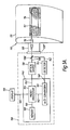
- the optical monitoring system 10 of Figure 1 is electrically passive and includes an optical fibre 12 which is supported by sheet 14 which is connected to aircraft wing 15.
- Optical fibre 12 is connected to connectors 16 and 17.
- the optical fibre mounting system and the method of installation thereof are useful for monitoring structures, such as wing 15, for stress, strain, etc.
- the supporting sheet 14 is preferably a structural fibre fabric in which the structural fibres are preferably graphite or glass.
- the optical fibre 12 and sheet 14 are readily stored in a roll, which is easily unwound and cut to the length desired to be affixed to the structure.
- connectors 16 and 17 are affixed to the ends of the cut length of optical fibre 12 and sheet 14 for connection to light source and detection system.
- the sheet 14 is preferably combined with resin and/or adhesive to adhere to or form part of the structure.
- Optical fibres useful in embodiments of the invention are characterized by attenuation or loss of light intensity of less than 100 dB per kilometre of optical fibre length as the light is propagated therethrough.
- the optical fibres include a cladding and a core having different indexes of refraction.
- Preferred optical fibres include a glass or plastic core.
- Optical fibres are adapted to guide coherent light without significant changes in the properties of the light due to the optical fibre in the absence of variations in its surroundings such as changes in temperature, pressure stress, strain, etc.
- Structural fibres useful in embodiments of the invention add substantial strength to composite structures.
- Such structural fibres may, for example, include structural glass fibres which are characterized by attenuation or loss of light intensity by 50 percent in 3 cm (or greater than 150 dB per kilometre) of structural glass fibre length for light propagated therethrough.
- Structural glass fibres are not composed of cores clad with transparent material.
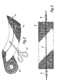
- optical fibre 12 and the sheet 14 connected thereto are shown being unrolled from roll 80, and then cut to the desired length using scissors 82.
- connectors 16 and 17 are then attached to the optical fibre 12.
- the optical fibre 12 is then fabricated onto a structure, such as wing 15 as shown in Figure 1.
- the fabricated structure is monitored by propagating light through the installed optical fibre and continuously monitoring the light to detect changes in temperature, pressure, stress and/or strain in the structure.
- the optical source 36 transmits electromagnetic radiation, such as light, through optical fibre 38 to fibre connector 16.
- Connector 16 connects fibres 12 and 38.
- Fibre 12 is connected via connector 17 to fibre 42.
- the fibres 12,38 and 42 may be single mode or multimode.
- the optical fibres 38 and 42 extend through connector 39 ⁇ and are protected by shielding 39.
- the optical fibre 42 channels light to optical detector 44.
- Optical detector 44 is connected to signal conditioning electronics 46 by electrical conductor 48.
- Signal conditioning electronics 46 is connected by electrical conductor 37 to optical source 36.
- Optical signal conditioner 58 includes source 36, detector 44 and signal conditioning electronics 46.
- Signal conditioning electronics 46 includes analog to digital (A/D) converter 60 which is connected by electrical conductor 48 to detector 44, and by electrical conductor 62 to microprocessor 64.
- A/D analog to digital
- Microprocessor 64 sends signals to and receives signals from memory 68 through electrical conductor 66, and is connected to display 70 by electrical conductor 69.
- the detector 44 is a means for detecting and indicating changes in the light signal provided by the optical source 36.
- the detector 44 detects the electromagnetic radiation propagating through optical fibres 12 and 42.
- the signal from detector 44 is converted to digital form in A/D converter 60 and fed into the microprocessor 64.
- Signals from the microprocessor 64 are displayed by display 70. Any type of physical movement of the optical fibre 12, such as slight bending, will have an effect upon at least one property of light propagated through the fibre. Changes in properties of the light result from the physical movement of the structure which moves the optical fibre 12.
- an optical time domain reflectometry monitoring system 110 is shown.
- System 110 is useful for detecting the magnitude and/or location of stress and/or strain in a structure, such as wing 115.
- the electrically passive optical monitoring system 110 includes an optical fibre 112 which is supported by sheet 114 which is connected to wing 115.
- the optical source 136 transmits electromagnetic radiation, such as light, through optical fibre 138 to fibre connector 116.
- Connector 116 connects fibres 112 and 138.
- the fibres 138 and 112 may be single mode or multimode.
- the optical fibre 138 extends through connector 139 ⁇ and is protected by shielding 139.
- An optical fibre 142 channels the light from coupler 138C to optical detector 144.
- Optical detector 144 is connected to signal conditioning electronics 146 by electrical conductor 148.
- Signal conditioning electronics 146 is connected by electrical conductor 150 to optical source 136.
- Optical signal conditioner 158 includes source 136, detector 144 and signal conditioning electronics 146.
- Signal conditioning electronics 146 includes analog to digital (A/D) converter 160 which is connected by electrical conductor 148 to detector 144, and by electrical conductor 162 to microprocessor 164.
- Microprocessor 164 sends signals to and receives signals from memory 168 through electrical conductor 166, and is connected to display 170 by electrical conductor 169.
- the detector 144 converts light from fibre 142 into a corresponding electrical signal. Changes in the properties of the light signal as it is propagated through the fibre 112 are caused by stress and strain in the wing 115.
- the detector 144 detects the light propagating through optical fibre 142. Variations in the intensity of the light reflected from fibre 112 are monitored by monitoring the corresponding electrical signal from detector 144. The location and magnitude of stress and strain are determined in microprocessor 164.
- Support sheets may be made of fibres and/or films.
- the support sheet may include an adhesive coating on at least one side thereof.
- the support sheet may include a release coating on at least one side thereof.
- the adhesive coating is on the opposite side of the sheet from the release coating.
- a release coated sheet may be positioned over the adhesive coating to prevent adhesion of the adhesive coating to the side of the sheet without an adhesive coating while the sheet is stored in a roll and during handling prior to installation of the sheet into or on the structure.
- the fibrous support sheet is preferably woven.
- Structures to be monitored may be made of metal sheeting, polymeric, (organic or inorganic) composite or other suitable material.
- Preferred organic polymeric materials include thermoplastic and thermoset polymers. These materials may include a matrix of metal, for example aluminium, thermoplastic such as polyetherether ketone (PEEK), thermoset polymer or ceramic.
- a preferred composite structure includes high strength filaments or fibres in a polymeric matrix such as a crosslinked epoxy or maleinide.
- the support sheet and optical fibre supported thereby are preferably incorporated into composite structures during fabrication.
- Composite structures are fabricated by forming a mixture of structural fibres and resin (prepreg).
- the resin is preferably adapted to form a thermoplastic or a thermoset polymer which encloses the structural fibres and supports the sheet which supports the optical fibre.
- the polymer and structural fibres form the shape of a desired structure such as a wing or a missile casing.
- Epoxy resins are well established for use in making high performance composite structures which include high strength fibre.
- Preferred fibre materials are metal, glass, boron, carbon, graphite, (continuous or chopped filaments) or the like, such as disclosed by Chu et al in the U.S. Patent No. 4,677,305. Structures made of these composites can weigh considerably less than their metal counterparts of equivalent strength and stiffness.
- the structures may be fabricated as taught by Gill et al (assigned to Hercules Incorporated) in U.S. Patent 4,581,086.
- Helical applicators may be used to deposit a ply or plies of continuous structural filaments into the form of the structure as taught by Gill et al in U.S. Patent 4,519,869 (Assignee, Hercules Incorporated).
- multiphase epoxy thermosets having rubber within a disperse phase may be used to make structures, as taught by Bard in U.S. Patent 4,680,076 (assigned to Hercules Incorporated).
- Optical fibres attached to the structural fabric may be embedded in or attached to these structures during fabrication. Attachment to the structures of the optical fibres after construction may be carried out using the same or a different matrix material than is used to fabricate the underlying structures.
- the changes in the intensity of the light transmitted through fibre 38 may be monitored by signal conditioning electronics 46 (Fig. 1) or 146 (Fig. 1A). Instead, the changes in the polarization state of the transmitted light can be monitored by signal conditioning electronics 46 (Fig. 1) or 146 (Fig. 1A). Alternatively another possibility is to use interferometrics to monitor the transmitted light.
Landscapes
- Chemical & Material Sciences (AREA)
- Analytical Chemistry (AREA)
- Physics & Mathematics (AREA)
- General Physics & Mathematics (AREA)
- Light Guides In General And Applications Therefor (AREA)
- Length Measuring Devices By Optical Means (AREA)
- Optical Transform (AREA)
- Woven Fabrics (AREA)
- Testing Or Calibration Of Command Recording Devices (AREA)
- Investigating Or Analysing Materials By Optical Means (AREA)
Applications Claiming Priority (2)
| Application Number | Priority Date | Filing Date | Title |
|---|---|---|---|
| US313262 | 1989-02-21 | ||
| US07/313,262 US4930852A (en) | 1989-02-21 | 1989-02-21 | Optical fiber mounting and structural monitoring |
Publications (2)
| Publication Number | Publication Date |
|---|---|
| EP0384649A2 true EP0384649A2 (de) | 1990-08-29 |
| EP0384649A3 EP0384649A3 (de) | 1991-05-15 |
Family
ID=23215015
Family Applications (1)
| Application Number | Title | Priority Date | Filing Date |
|---|---|---|---|
| EP19900301632 Withdrawn EP0384649A3 (de) | 1989-02-21 | 1990-02-15 | Anordnung und Verfahren zur Montage von optischen Fasern |
Country Status (5)
| Country | Link |
|---|---|
| US (1) | US4930852A (de) |
| EP (1) | EP0384649A3 (de) |
| JP (1) | JPH0333244A (de) |
| CA (1) | CA2010447A1 (de) |
| IL (1) | IL93467A0 (de) |
Cited By (3)
| Publication number | Priority date | Publication date | Assignee | Title |
|---|---|---|---|---|
| EP0573778A1 (de) * | 1992-05-08 | 1993-12-15 | Rockwell International Corporation | Faseroptischer Sensor für Verbindungsstellen |
| WO1999061875A1 (en) * | 1998-05-26 | 1999-12-02 | Minnesota Mining And Manufacturing Company | Sensing tapes for strain and/or temperature sensing |
| EP1883725A2 (de) * | 2005-05-27 | 2008-02-06 | Milliken&Company | Glasfasersubstrat als komponente für sensor oder beleuchtungsvorrichtung |
Families Citing this family (22)
| Publication number | Priority date | Publication date | Assignee | Title |
|---|---|---|---|---|
| US5250802A (en) * | 1991-11-04 | 1993-10-05 | Teledyne Ryan Aeronautical, Division Of Teledyne Industries, Inc. | Fiber optic stress sensor for structural joints |
| WO1993025866A1 (en) * | 1992-06-05 | 1993-12-23 | Monash University | Sensing patches utilising incorporated waveguide sensor |
| CA2103652A1 (en) * | 1992-08-10 | 1994-02-11 | Kenji Furuichi | Safety apparatus for fuel tank |
| ATE201787T1 (de) * | 1992-11-25 | 2001-06-15 | Simmonds Precision Products | Datenverarbeitungsstrukturen und methoden |
| US5355429A (en) * | 1992-12-30 | 1994-10-11 | Minnesota Mining And Manufacturing Company | Optical fiber strain relief apparatus |
| US5433115A (en) * | 1993-06-14 | 1995-07-18 | Simmonds Precision Products, Inc. | Contactless interrogation of sensors for smart structures |
| US5515041A (en) * | 1993-06-14 | 1996-05-07 | Simmonds Precision Products Inc. | Composite shaft monitoring system |
| US5602540A (en) * | 1993-06-14 | 1997-02-11 | Simmonds Precision Products Inc. | Fluid gauging apparatus with inductive interrogation |
| US5581248A (en) * | 1993-06-14 | 1996-12-03 | Simmonds Precision Products, Inc. | Embeddable device for contactless interrogation of sensors for smart structures |
| CN1422350A (zh) * | 2000-04-12 | 2003-06-04 | 光线有限公司 | 用以进一步传输入射光的产品和生产该产品的方法以及该产品和方法的使用 |
| CA2386884C (en) * | 2001-05-29 | 2010-02-09 | Queen's University At Kingston | Optical loop ring-down |
| KR20040073461A (ko) * | 2001-12-08 | 2004-08-19 | 우벤 알로이즈 | 경보등을 구비한 풍력 설비의 로터 블레이드 |
| US7578199B2 (en) * | 2003-08-27 | 2009-08-25 | Airbus Uk Limited | Apparatus and method suitable for measuring the displacement or load on an aircraft component |
| GB2405934A (en) * | 2003-09-09 | 2005-03-16 | Qinetiq Ltd | Resistance strain/moisture gauge |
| WO2008021881A2 (en) * | 2006-08-09 | 2008-02-21 | Shell Oil Company | Method of applying a string of interconnected strain sensors to an object, a pliable support structure, and method of producing a mineral hydrocarbon fluid |
| GB0722319D0 (en) * | 2007-11-14 | 2007-12-27 | Rolls Royce Plc | Component monitoring arrangement |
| US7777496B2 (en) * | 2008-07-18 | 2010-08-17 | The United States Of America As Represented By The Secretary Of The Army | Remote sensor system for monitoring the condition of earthen structure and method of its use |
| WO2010025159A1 (en) | 2008-08-27 | 2010-03-04 | Shell Oil Company | Monitoring system for well casing |
| FR3010522B1 (fr) * | 2013-09-06 | 2017-04-28 | Airbus Operations Sas | Systeme de controle non destructif d'une piece en materiau composite et aeronef comprenant un tel systeme |
| EP3557214B1 (de) * | 2018-04-20 | 2022-08-24 | Hamilton Sundstrand Corporation | Blatt für einen propeller mit blattverbundstruktur und einem in die blattverbundstruktur eingebetteten extrinsic fabry-perot interferometric sensor |
| CN111351633A (zh) * | 2018-12-20 | 2020-06-30 | 中国移动通信集团四川有限公司 | 光纤交接箱的监控装置、方法、系统、设备和介质 |
| MY201978A (en) * | 2019-09-13 | 2024-03-27 | Petroliam Nasional Berhad | Optical cable |
Family Cites Families (30)
| Publication number | Priority date | Publication date | Assignee | Title |
|---|---|---|---|---|
| US2523865A (en) * | 1947-06-27 | 1950-09-26 | Bigelow Sanford Carpet Co Inc | Tape and carpet joined therewith |
| US2787570A (en) * | 1954-03-17 | 1957-04-02 | Gen Tire & Rubber Co | Reinforced sheet material |
| GB841200A (en) * | 1956-09-17 | 1960-07-13 | American Optical Corp | Improvements in or relating to electronic image forming tubes |
| US3599679A (en) * | 1968-10-22 | 1971-08-17 | Monsanto Co | Inextensible filamentary structure and fabrics woven therefrom |
| US4097460A (en) * | 1971-07-23 | 1978-06-27 | Hercules Incorporated | Poly(arylacetylenes) and thermoset resins therefrom |
| US4070333A (en) * | 1972-06-12 | 1978-01-24 | Hercules Incorporated | Poly(arylacetylene) molding compositions |
| US4144218A (en) * | 1977-07-08 | 1979-03-13 | Hercules Incorporated | Thermosetting compositions containing a poly (arylacetylene) and a poly (phenylene oxide) |
| US4138193A (en) * | 1977-09-27 | 1979-02-06 | General Cable Corporation | Multiple fiber laminate for optical waveguides |
| US4307386A (en) * | 1977-12-09 | 1981-12-22 | Roderick Iain Davidson | Security system and strip or strand incorporating fibre-optic wave guide means therefor |
| US4239335A (en) * | 1978-08-28 | 1980-12-16 | Sea-Log Corporation | Fiber reinforced optical fiber cable |
| DE2938649A1 (de) * | 1978-09-28 | 1980-04-10 | Australian Telecomm | Vorrichtung und verfahren zur signaluebertragung in lichtleitern |
| US4355865A (en) * | 1980-03-21 | 1982-10-26 | Amp Incorporated | Laminated optical fiber cable |
| DE3142392A1 (de) * | 1981-03-26 | 1983-05-11 | Vereinigte Flugtechnische Werke Gmbh, 2800 Bremen | Messanordnung zum feststellen von rissen |
| DE3111858A1 (de) * | 1981-03-26 | 1982-10-14 | Vereinigte Flugtechnische Werke Gmbh, 2800 Bremen | Messanordnung zum feststellen von rissen |
| US4422719A (en) * | 1981-05-07 | 1983-12-27 | Space-Lyte International, Inc. | Optical distribution system including light guide |
| US4654520A (en) * | 1981-08-24 | 1987-03-31 | Griffiths Richard W | Structural monitoring system using fiber optics |
| US4812645A (en) * | 1981-08-24 | 1989-03-14 | G2 Systems Corporation | Structural monitoring system using fiber optics |
| US4581086A (en) * | 1982-01-07 | 1986-04-08 | Hercules Incorporated | Fabricating large, thick wall, tubular structures |
| DE3243026A1 (de) * | 1982-05-15 | 1984-05-24 | Messerschmitt-Bölkow-Blohm GmbH, 8012 Ottobrunn | Messanordnung zum feststellen von rissen |
| CA1212529A (en) * | 1982-07-08 | 1986-10-14 | Dee R. Gill | Manufacture of filamentary composites |
| EP0116685A1 (de) * | 1982-11-20 | 1984-08-29 | Messerschmitt-Bölkow-Blohm Gesellschaft mit beschränkter Haftung | Optische Messanordnung zum Feststellen von Rissen |
| ZA844474B (en) * | 1983-06-17 | 1985-02-27 | Bicc Plc | Optical fibre ribbon structure |
| DE3343510A1 (de) * | 1983-12-01 | 1985-06-13 | Westland PLC, Yeovil, Somerset | Einrichtung zum anzeigen des ansatzes von rissen oder bruechen |
| GB8406144D0 (en) * | 1984-03-08 | 1984-04-11 | French S | Decorative floor-covering |
| US4537469A (en) * | 1984-05-25 | 1985-08-27 | Grumman Aerospace Corporation | Multi-function composite material utilizing embedded optical fibers |
| DE3447122A1 (de) * | 1984-12-22 | 1986-06-26 | Messerschmitt-Bölkow-Blohm GmbH, 2800 Bremen | Messanordnung zum feststellen von rissen in prueflingen |
| US4656208A (en) * | 1985-02-19 | 1987-04-07 | Hercules Incorporated | Thermosetting epoxy resin compositions and thermosets therefrom |
| US4677305A (en) * | 1985-06-28 | 1987-06-30 | Simmonds Precision Products, Inc. | Opto-acoustic fuel quantity gauging system |
| US4734577A (en) * | 1986-01-30 | 1988-03-29 | Grumman Aerospace Corporation | Continuous strain measurement along a span |
| US4680076A (en) * | 1986-08-28 | 1987-07-14 | Hercules Incorporated | Multiphase epoxy thermosets having rubber within disperse phase |
-
1989
- 1989-02-21 US US07/313,262 patent/US4930852A/en not_active Expired - Lifetime
-
1990
- 1990-02-15 EP EP19900301632 patent/EP0384649A3/de not_active Withdrawn
- 1990-02-20 CA CA002010447A patent/CA2010447A1/en not_active Abandoned
- 1990-02-20 IL IL93467A patent/IL93467A0/xx unknown
- 1990-02-21 JP JP2038516A patent/JPH0333244A/ja active Pending
Cited By (4)
| Publication number | Priority date | Publication date | Assignee | Title |
|---|---|---|---|---|
| EP0573778A1 (de) * | 1992-05-08 | 1993-12-15 | Rockwell International Corporation | Faseroptischer Sensor für Verbindungsstellen |
| WO1999061875A1 (en) * | 1998-05-26 | 1999-12-02 | Minnesota Mining And Manufacturing Company | Sensing tapes for strain and/or temperature sensing |
| US6215927B1 (en) | 1998-05-26 | 2001-04-10 | Minnesota Mining & Maufacturing Company | Sensing tapes for strain and/or temperature sensing |
| EP1883725A2 (de) * | 2005-05-27 | 2008-02-06 | Milliken&Company | Glasfasersubstrat als komponente für sensor oder beleuchtungsvorrichtung |
Also Published As
| Publication number | Publication date |
|---|---|
| EP0384649A3 (de) | 1991-05-15 |
| CA2010447A1 (en) | 1990-08-21 |
| IL93467A0 (en) | 1990-11-29 |
| JPH0333244A (ja) | 1991-02-13 |
| US4930852A (en) | 1990-06-05 |
Similar Documents
| Publication | Publication Date | Title |
|---|---|---|
| US4930852A (en) | Optical fiber mounting and structural monitoring | |
| US5029977A (en) | Mounting system | |
| EP0401153B1 (de) | Fiberoptisches Defektmeldesystem | |
| US5649035A (en) | Fiber optic strain gauge patch | |
| US4634217A (en) | High tensile wire provided with light guide sensor | |
| US4772092A (en) | Crack detection arrangement utilizing optical fibres as reinforcement fibres | |
| US5256468A (en) | Smart skin array woven fiber optic ribbon and arrays and packaging thereof | |
| US4936649A (en) | Damage evaluation system and method using optical fibers | |
| US5355429A (en) | Optical fiber strain relief apparatus | |
| US4537469A (en) | Multi-function composite material utilizing embedded optical fibers | |
| EP1672351B1 (de) | Herstellungsverfahren für die Herstellung eines modularen Sensors zur Schadensdetektion | |
| US8172180B2 (en) | Temperature monitoring | |
| US20070196059A1 (en) | Tape-shaped optical fiber cable | |
| EP3639001B1 (de) | Sensortextilien | |
| US5094527A (en) | Temperature compensated strain sensor for composite structures | |
| GB2440955A (en) | Wind turbine blade monitoring | |
| CN109901272B (zh) | 一种多芯光纤智能复合筋、制备方法以及安全监测方法 | |
| JPS648770B2 (de) | ||
| Kang et al. | Development of fibre optic ingress/egress methods for smart composite structures | |
| EP1217350B1 (de) | Sensor für mechanische Spannungen, mit periodisch angeordneten farbveränderlichen taktilen Folien, zur Detektion einer falschen Handhabung von optischen Fasern | |
| CA1131953A (en) | Optical fibre transmission cable reinforcement | |
| CN116009170B (zh) | 一种adss光缆融冰系统 | |
| CN111811685A (zh) | 一种光纤光栅温度传感器、组件及制作方法 | |
| GB2036336A (en) | Measuring stress and strain using optical fibres | |
| CN215262041U (zh) | 一种传感光缆 |
Legal Events
| Date | Code | Title | Description |
|---|---|---|---|
| PUAI | Public reference made under article 153(3) epc to a published international application that has entered the european phase |
Free format text: ORIGINAL CODE: 0009012 |
|
| AK | Designated contracting states |
Kind code of ref document: A2 Designated state(s): DE FR GB IT NL SE |
|
| PUAL | Search report despatched |
Free format text: ORIGINAL CODE: 0009013 |
|
| AK | Designated contracting states |
Kind code of ref document: A3 Designated state(s): DE FR GB IT NL SE |
|
| 17P | Request for examination filed |
Effective date: 19911016 |
|
| 17Q | First examination report despatched |
Effective date: 19921104 |
|
| STAA | Information on the status of an ep patent application or granted ep patent |
Free format text: STATUS: THE APPLICATION IS DEEMED TO BE WITHDRAWN |
|
| 18D | Application deemed to be withdrawn |
Effective date: 19930515 |