EP0384663A1 - Ventiltriebvorrichtung mit elektromagnetischer Kraft - Google Patents
Ventiltriebvorrichtung mit elektromagnetischer Kraft Download PDFInfo
- Publication number
- EP0384663A1 EP0384663A1 EP90301698A EP90301698A EP0384663A1 EP 0384663 A1 EP0384663 A1 EP 0384663A1 EP 90301698 A EP90301698 A EP 90301698A EP 90301698 A EP90301698 A EP 90301698A EP 0384663 A1 EP0384663 A1 EP 0384663A1
- Authority
- EP
- European Patent Office
- Prior art keywords
- magnetic pole
- inlet
- valve
- exhaust valve
- movable magnetic
- Prior art date
- Legal status (The legal status is an assumption and is not a legal conclusion. Google has not performed a legal analysis and makes no representation as to the accuracy of the status listed.)
- Granted
Links
Images
Classifications
-
- F—MECHANICAL ENGINEERING; LIGHTING; HEATING; WEAPONS; BLASTING
- F01—MACHINES OR ENGINES IN GENERAL; ENGINE PLANTS IN GENERAL; STEAM ENGINES
- F01L—CYCLICALLY OPERATING VALVES FOR MACHINES OR ENGINES
- F01L9/00—Valve-gear or valve arrangements actuated non-mechanically
- F01L9/20—Valve-gear or valve arrangements actuated non-mechanically by electric means
Definitions
- This invention relates to an electromagnetic force valve driving apparatus for opening and closing the inlet/exhaust valve of an engine by an electromagnetic force produced by an electromagnet.
- a camshaft on which cams for inlet and exhaust are disposed is provided on the upper portion of the engine or on one side thereof.
- a crankshaft and the camshaft are connected by rotary transmission means such as a belt, and the camshaft is driven rotationally in synchronism with the rotational phase of the engine.
- the cam face of the camshaft and the axial end face of the valve are connected via a link mechanism such as a rocker arm or push rod.
- the inlet/exhaust valve which is biased in the closing direction at all times by a valve spring, is driven in the opening direction by the link mechanism which acts to push the axial end face of the valve.
- valve timing cannot be altered during engine operation. Since the valve timing is adjusted in conformity with the rotational speed of the engine, engine output and efficiency decline when the engine is running at a speed (rpm) different from the prescribed speed.
- the distance between the magnetic pole of the electromagnet and the movable magnetic pole is at a maximum at the moment that the attractive force starts acting upon the movable magnetic pole. Consequently, the attractive force between the magnetic pole of the electromagnet and the movable magnetic pole is at a minimum at this time. Accordingly, acceleration of the movable magnetic pole immediately after it starts moving is low, and therefore the size of the opening of the valve operatively associated with the movable magnetic pole is small.
- the distance between the electromagnet and the movable magnetic pole is large even in the case where a braking force is applied to the movable magnetic pole just prior to valve seating in order to mitigate shock when the valve is seated, as described in the specification of Japanese Patent Application Laid-Open no. 61-76713, the braking force is too small to reduce the seating shock sufficiently.
- the present invention has been devised in view of the foregoing points and its object is to provide an electromagnetic force valve driving apparatus in which the magnetic force that acts upon the valve is maximised when the valve starts moving and when the valve is seated.
- an electromagnetic force valve driving apparatus comprising a freely reciprocable movable magnetic pole connected to an inlet/exhaust valve, an upper fixed magnetic pole opposing one end of the movable magnetic pole, a first electromagnet comprising a yoke member communicating with the upper fixed magnetic pole and having a lower magnetic pole opposing the other end of the movable magnetic pole, a second electromagnet having a magnetic pole opposing the upper magnetic pole and the one end of the movable magnetic pole, a spring for subjecting the movable magnetic pole to a force which moves the pole in the direction of the one end thereof, and energizing control means for energizing the first and second electromagnets when the inlet/exhaust valve is released and immediately before it is seated, thereby causing a repulsive force to act between the one end of the movable magnetic pole and the upper fixed magnetic pole.
- a repulsive force is caused to act between the one end of the movable magnetic pole and the upper fixed magnetic pole when the inlet/exhaust valve is released.
- the repulsive force drives the inlet/exhaust valve in the opening direction.
- Energization is resumed for a prescribed period of time just prior to seating of the valve, thereby decelerating the valve in the closing direction to mitigate seating shock.
- an electromagnetic force valve driving apparatus for high output and superlative fuel economy in which driving of the inlet/exhaust valve in the opening direction and braking of the valve at seating are achieved by an electromagnetic force, and a large amount of drive in the opening direction as well as a large acceleration at seating is obtained.
- the degree to which the inlet/exhaust valve opens is enlarged, i.e., the inlet/exhaust resistance is diminished.
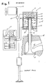
- An engine 6 has an inlet valve for opening and closing the inlet port of a cylinder, and a discharge valve for opening and closing the discharge port of the cylinder.
- the discussion that follows will deal primarily with the inlet valve.
- Numeral 4 denotes the inlet valve, which is formed of a heat-resistant, light weight ceramic. It is also permissible to form the inlet valve 4 of a heat-resistant alloy, as in the prior art.
- the inlet valve 4 is axially supported by a valve guide 41 so as to slidable in the axial direction and has a bevelled portion which is seated on a valve seat 42 disposed at the outlet of an intake conduit 43, thereby closing the inlet port.
- a movable magnetic pole 3 comprising a magnetic material is fixedly secured to the axial end portion of the inlet valve 4 by a fixing member 33.
- the axial end portion of the movable magnetic pole 3 is formed to have a radially projecting end magnetic pole 31.
- An upper electromagnet 1 is disposed in close proximity to the end magnetic pole 31 on the upper side thereof and comprises a central magnetic pole 12 opposing the end magnetic pole 31, a peripheral magnetic pole 13 opposing the central magnetic pole 12, and an upper coil 11 for producing magnetic lines of force in the central magnetic pole 12 and peripheral magnetic pole 13.
- a lower electromagnet 2 is provided about the outer periphery of the movable magnetic pole 3 and comprises an upper magnetic pole 23 opposing the peripheral magnetic pole 13 and the end magnetic pole 31, a lower magnetic pole 22 opposing the outer peripheral surface of the movable magnetic pole 3, and a lower coil 21 for generating magnetic lines of force in the upper magnetic pole 23 and the lower magnetic pole 22.
- a spring 32 for applying an upwardly directed force to the inlet valve 4 via the movable magnetic pole 3 is disposed between the end magnetic pole 31 and the lower magnetic pole 22.
- the upper coil 11 and the lower coil 21 are connected to an input/output interface 54 within a control unit 5.
- a rotary sensor 61 Connected to the input/output interface 54 in addition to the upper coil 11 and lower coil 21 is a rotary sensor 61 provided in close proximity to the output shaft of the engine 6.
- the control unit 5 comprises, in addition to the input/output interface 54 which supervises signal input/output with the external equipment, a ROM 52 in which programs and data are stored in advance, a CPU 51 for performing processing under control of the programs stored in the ROM 52, a RAM 53 for temporarily storing input signals and the results of processing, and a control memory 55 for controlling the flow of signals within the control unit 5.
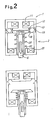
- Figure 2 is a view illustrating the upper electromagnet 1 and lower electromagnet 2, which constitute the valve drive section. The cross-section hatching in Figure 1 has been removed from Figure 2.
- the inlet valve 4 is urged upwardly by the spring 32 and held at a position where it is seated on the valve seat 42.
- a current is passed through the upper coil 11 in such a manner that a North (N) pole is produced in the central magnetic pole 12 and a South (S) pole in the peripheral magnetic pole 13.
- a current is passed through the lower coil 21 as well to produce an N pole in the lower magnetic pole 22 and an S pole in the upper magnetic pole 23.
- the inlet valve 4 When the inlet valve 4 is thus driven downwardly to increase the distance between the end magnetic pole 31 and central magnetic pole 12, the repulsive force decreases and the upwardly directed force produced by the spring 32 increases.
- the inlet valve 4 stops at a position where the downward repulsive force and the upward spring force balance each other.
- a table giving the correlation between each set time period and engine rpm is stored in the ROM 52 beforehand.
- the first, second and third times mentioned above are obtained by calculating the set time corresponding to engine rpm from the rpm of the engine 6, which is sensed by the rotation sensor 61, and the correlation table.
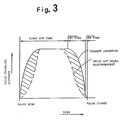
- Figure 3 shows so-called cam profile curves, in which the horizontal axis represents the opening timing of the inlet valve 4, and the vertical axis represents the amount of valve movement.
- the curves in this diagram indicate the change in the amount of movement of the inlet valve with the passage of time.
- the curve indicated by the solid line is that according to the present invention, while the curve indicated by the dashed line is that obtained with the conventional apparatus using electromagnets.
- the valve In the conventional apparatus associated with the curve indicated by the dashed line, the valve is driven by an attractive force produced electromagnetically.
- the attractive force is at a minimum at the moment the force begins to act, and the distance over which the electromagnetic force acts diminishes with movement of the valve, as a result of which the attractive force increases. Accordingly, acceleration immediately after the start of movement is low. On the other hand, in the apparatus of the present invention, the acceleration is high immediately after the valve begins moving, as described above.
- the area defined between the profile curve and the horizontal axis indicates the degree of valve opening. It will be understood that this area, as obtained with the apparatus of the present invention, is larger than that of the prior art by the amount indicated by the shaded portions.
- the apparatus of the present invention is such that inlet/discharge resistance at the opening of an inlet/discharge valve is smaller than in the prior art apparatus and the performance of the engine 6 is improved over the prior-art apparatus.
- a map giving the correlation between engine rpm and valve opening timing can be stored in the ROM 52 in advance, and engine output and efficiency can be improved over the entire region of engine rpm by altering the valve opening timing as the rotational speed of the engine 6 changes.
Landscapes
- Engineering & Computer Science (AREA)
- Mechanical Engineering (AREA)
- General Engineering & Computer Science (AREA)
- Valve Device For Special Equipments (AREA)
- Magnetically Actuated Valves (AREA)
- Electromagnets (AREA)
Applications Claiming Priority (2)
| Application Number | Priority Date | Filing Date | Title |
|---|---|---|---|
| JP38429/89 | 1989-02-20 | ||
| JP1038429A JP2772534B2 (ja) | 1989-02-20 | 1989-02-20 | 電磁力バルブ駆動装置 |
Publications (2)
| Publication Number | Publication Date |
|---|---|
| EP0384663A1 true EP0384663A1 (de) | 1990-08-29 |
| EP0384663B1 EP0384663B1 (de) | 1995-01-25 |
Family
ID=12525067
Family Applications (1)
| Application Number | Title | Priority Date | Filing Date |
|---|---|---|---|
| EP90301698A Expired - Lifetime EP0384663B1 (de) | 1989-02-20 | 1990-02-16 | Ventiltriebvorrichtung mit elektromagnetischer Kraft |
Country Status (4)
| Country | Link |
|---|---|
| US (1) | US5009389A (de) |
| EP (1) | EP0384663B1 (de) |
| JP (1) | JP2772534B2 (de) |
| DE (1) | DE69016223T2 (de) |
Cited By (6)
| Publication number | Priority date | Publication date | Assignee | Title |
|---|---|---|---|---|
| FR2751695A1 (fr) * | 1996-07-26 | 1998-01-30 | Daimler Benz Ag | Moteur a combustion interne sans circuit d'huile de graissage |
| DE19854377A1 (de) * | 1998-11-25 | 2000-05-31 | Bayerische Motoren Werke Ag | Herstellverfahren für einen stößelgeführten Anker eines Aktuators für Hubventile einer Brennkraftmaschine |
| FR2799302A1 (fr) * | 1999-10-04 | 2001-04-06 | Peugeot Citroen Automobiles Sa | Actionneur electrique notamment pour soupape de moteur de vehicule automobile |
| EP1052381A3 (de) * | 1999-05-12 | 2002-06-12 | Toyota Jidosha Kabushiki Kaisha | Elektromagnetische Hubventilsteuerungseinrichtung für eine Brennkraftmaschine |
| US6532919B2 (en) | 2000-12-08 | 2003-03-18 | Ford Global Technologies, Inc. | Permanent magnet enhanced electromagnetic valve actuator |
| EP1318279A1 (de) * | 2001-12-04 | 2003-06-11 | Ford Global Technologies, Inc. | Elektromagnetischer Ventilaktuator mit Unterstützung durch Dauermagnet |
Families Citing this family (14)
| Publication number | Priority date | Publication date | Assignee | Title |
|---|---|---|---|---|
| JP2759329B2 (ja) * | 1988-12-28 | 1998-05-28 | 株式会社いすゞセラミックス研究所 | 電磁力バルブ駆動装置 |
| DE4142996A1 (de) * | 1991-12-24 | 1993-07-01 | Bosch Gmbh Robert | Verfahren zum messen der mechanischen bewegung eines magnetventilankers, insbesondere von elektrisch gesteuerten einspritzanlagen |
| US5515818A (en) * | 1993-12-15 | 1996-05-14 | Machine Research Corporation Of Chicago | Electromechanical variable valve actuator |
| US5417403A (en) * | 1994-01-14 | 1995-05-23 | Cummins Engine Company, Inc. | Captured ring and threaded armature solenoid valve |
| US6308690B1 (en) * | 1994-04-05 | 2001-10-30 | Sturman Industries, Inc. | Hydraulically controllable camless valve system adapted for an internal combustion engine |
| DE19531437A1 (de) * | 1995-08-26 | 1997-02-27 | Fev Motorentech Gmbh & Co Kg | Verfahren zur Erfassung des Ventilspiels an einem durch einen elektromagnetischen Aktuator betätigten Gaswechselventil |
| US5865371A (en) * | 1996-07-26 | 1999-02-02 | Siemens Automotive Corporation | Armature motion control method and apparatus for a fuel injector |
| US5991143A (en) * | 1998-04-28 | 1999-11-23 | Siemens Automotive Corporation | Method for controlling velocity of an armature of an electromagnetic actuator |
| DE19830667C2 (de) * | 1998-07-09 | 2002-10-31 | Daimler Chrysler Ag | Vorrichtung zur Bestimmung der Öffnungs- und Schließzeitpunkte eines Gaswechselventiles |
| US6128175A (en) * | 1998-12-17 | 2000-10-03 | Siemens Automotive Corporation | Apparatus and method for electronically reducing the impact of an armature in a fuel injector |
| US6476599B1 (en) | 1999-03-25 | 2002-11-05 | Siemens Automotive Corporation | Sensorless method to determine the static armature position in an electronically controlled solenoid device |
| US6359435B1 (en) | 1999-03-25 | 2002-03-19 | Siemens Automotive Corporation | Method for determining magnetic characteristics of an electronically controlled solenoid |
| DE19954416A1 (de) * | 1999-11-12 | 2001-05-17 | Bayerische Motoren Werke Ag | Verfahren zum Anschwingen eines elektromagnetischen Aktuators |
| JP6768589B2 (ja) * | 2017-04-21 | 2020-10-14 | 小倉クラッチ株式会社 | 励磁装置および無励磁作動ブレーキ |
Citations (2)
| Publication number | Priority date | Publication date | Assignee | Title |
|---|---|---|---|---|
| US4392632A (en) * | 1980-07-10 | 1983-07-12 | Robert Bosch Gmbh | Electromagnetic valve with a plug member comprising a permanent magnet |
| EP0281192A1 (de) * | 1987-03-03 | 1988-09-07 | Magnavox Government and Industrial Electronics Company | Elektromagnetische Ventilsteuerung |
Family Cites Families (3)
| Publication number | Priority date | Publication date | Assignee | Title |
|---|---|---|---|---|
| JPS55159377A (en) * | 1979-05-26 | 1980-12-11 | Aisin Seiki Co Ltd | Control method and apparatus for solenoid valve |
| US4726389A (en) * | 1986-12-11 | 1988-02-23 | Aisan Kogyo Kabushiki Kaisha | Method of controlling injector valve |
| JP3355676B2 (ja) * | 1992-12-01 | 2002-12-09 | 株式会社村田製作所 | 偏向ヨーク |
-
1989
- 1989-02-20 JP JP1038429A patent/JP2772534B2/ja not_active Expired - Lifetime
-
1990
- 1990-02-15 US US07/480,578 patent/US5009389A/en not_active Expired - Fee Related
- 1990-02-16 DE DE69016223T patent/DE69016223T2/de not_active Expired - Fee Related
- 1990-02-16 EP EP90301698A patent/EP0384663B1/de not_active Expired - Lifetime
Patent Citations (2)
| Publication number | Priority date | Publication date | Assignee | Title |
|---|---|---|---|---|
| US4392632A (en) * | 1980-07-10 | 1983-07-12 | Robert Bosch Gmbh | Electromagnetic valve with a plug member comprising a permanent magnet |
| EP0281192A1 (de) * | 1987-03-03 | 1988-09-07 | Magnavox Government and Industrial Electronics Company | Elektromagnetische Ventilsteuerung |
Non-Patent Citations (2)
| Title |
|---|
| AUTOMOTIVE ENGINEERING. vol. 96, no. 12, December 1988, WARRENDALE US pages 59 - 64; "Ceramics in internal combustion engines" * |
| PATENT ABSTRACTS OF JAPAN vol. 7, no. 203 (M-241)(1348) 08 September 1983, & JP-A-58 101206 (AICHI) 16 June 1983, * |
Cited By (7)
| Publication number | Priority date | Publication date | Assignee | Title |
|---|---|---|---|---|
| FR2751695A1 (fr) * | 1996-07-26 | 1998-01-30 | Daimler Benz Ag | Moteur a combustion interne sans circuit d'huile de graissage |
| DE19854377A1 (de) * | 1998-11-25 | 2000-05-31 | Bayerische Motoren Werke Ag | Herstellverfahren für einen stößelgeführten Anker eines Aktuators für Hubventile einer Brennkraftmaschine |
| EP1052381A3 (de) * | 1999-05-12 | 2002-06-12 | Toyota Jidosha Kabushiki Kaisha | Elektromagnetische Hubventilsteuerungseinrichtung für eine Brennkraftmaschine |
| FR2799302A1 (fr) * | 1999-10-04 | 2001-04-06 | Peugeot Citroen Automobiles Sa | Actionneur electrique notamment pour soupape de moteur de vehicule automobile |
| EP1091368A1 (de) * | 1999-10-04 | 2001-04-11 | Peugeot Citroen Automobiles SA | Elektrische Betätigungsvorrichtung, insbesondere für ein Fahrzeugmotorventil |
| US6532919B2 (en) | 2000-12-08 | 2003-03-18 | Ford Global Technologies, Inc. | Permanent magnet enhanced electromagnetic valve actuator |
| EP1318279A1 (de) * | 2001-12-04 | 2003-06-11 | Ford Global Technologies, Inc. | Elektromagnetischer Ventilaktuator mit Unterstützung durch Dauermagnet |
Also Published As
| Publication number | Publication date |
|---|---|
| EP0384663B1 (de) | 1995-01-25 |
| DE69016223D1 (de) | 1995-03-09 |
| US5009389A (en) | 1991-04-23 |
| DE69016223T2 (de) | 1995-05-24 |
| JPH02218808A (ja) | 1990-08-31 |
| JP2772534B2 (ja) | 1998-07-02 |
Similar Documents
| Publication | Publication Date | Title |
|---|---|---|
| EP0384663B1 (de) | Ventiltriebvorrichtung mit elektromagnetischer Kraft | |
| US4955334A (en) | Control apparatus for valve driven by electromagnetic force | |
| US5095856A (en) | Electromagnetic valve actuating system | |
| EP0367553A1 (de) | Ventilsteuerungsvorrichtung für Brennkraftmaschinen | |
| JP2596459B2 (ja) | バルブの電磁力駆動装置 | |
| US5111779A (en) | Electromagnetic valve actuating system | |
| EP0394492B1 (de) | Elektromagnetisch angetriebene ventilregelungseinheit | |
| US5076221A (en) | Electromagnetic valve actuating system | |
| US6532919B2 (en) | Permanent magnet enhanced electromagnetic valve actuator | |
| US5765513A (en) | Electromechanically actuated valve | |
| EP0367552B1 (de) | Ventilsteuerungsvorrichtung für Brennkraftmaschinen | |
| EP0406444A1 (de) | Elektromagnetischer ventilbetätiger | |
| US5119772A (en) | Electromagnetic valve actuating system | |
| JPH0129965B2 (de) | ||
| JP2982009B2 (ja) | 電磁力バルブ駆動装置 | |
| EP1052381A3 (de) | Elektromagnetische Hubventilsteuerungseinrichtung für eine Brennkraftmaschine | |
| JPH0392518A (ja) | 電磁力バルブ駆動装置 | |
| EP1318279B1 (de) | Elektromagnetischer Ventilaktuator mit Unterstützung durch Dauermagnet | |
| JP2005105887A (ja) | エンジンの動弁装置 | |
| JPH03185207A (ja) | 電磁力バルブ駆動装置 | |
| JPH03182611A (ja) | 電磁力バルブ駆動装置 |
Legal Events
| Date | Code | Title | Description |
|---|---|---|---|
| PUAI | Public reference made under article 153(3) epc to a published international application that has entered the european phase |
Free format text: ORIGINAL CODE: 0009012 |
|
| AK | Designated contracting states |
Kind code of ref document: A1 Designated state(s): DE FR GB |
|
| 17P | Request for examination filed |
Effective date: 19901207 |
|
| 17Q | First examination report despatched |
Effective date: 19910318 |
|
| GRAA | (expected) grant |
Free format text: ORIGINAL CODE: 0009210 |
|
| AK | Designated contracting states |
Kind code of ref document: B1 Designated state(s): DE FR GB |
|
| REF | Corresponds to: |
Ref document number: 69016223 Country of ref document: DE Date of ref document: 19950309 |
|
| ET | Fr: translation filed | ||
| PGFP | Annual fee paid to national office [announced via postgrant information from national office to epo] |
Ref country code: GB Payment date: 19950725 Year of fee payment: 6 |
|
| PGFP | Annual fee paid to national office [announced via postgrant information from national office to epo] |
Ref country code: FR Payment date: 19950809 Year of fee payment: 6 Ref country code: DE Payment date: 19950809 Year of fee payment: 6 |
|
| PLBE | No opposition filed within time limit |
Free format text: ORIGINAL CODE: 0009261 |
|
| STAA | Information on the status of an ep patent application or granted ep patent |
Free format text: STATUS: NO OPPOSITION FILED WITHIN TIME LIMIT |
|
| 26N | No opposition filed | ||
| PG25 | Lapsed in a contracting state [announced via postgrant information from national office to epo] |
Ref country code: GB Effective date: 19960216 |
|
| GBPC | Gb: european patent ceased through non-payment of renewal fee |
Effective date: 19960216 |
|
| PG25 | Lapsed in a contracting state [announced via postgrant information from national office to epo] |
Ref country code: FR Effective date: 19961031 |
|
| PG25 | Lapsed in a contracting state [announced via postgrant information from national office to epo] |
Ref country code: DE Effective date: 19961101 |
|
| REG | Reference to a national code |
Ref country code: FR Ref legal event code: ST |