EP0384746A2 - Milieu d'enregistrement magnéto-optique pouvant être surécrit - Google Patents
Milieu d'enregistrement magnéto-optique pouvant être surécrit Download PDFInfo
- Publication number
- EP0384746A2 EP0384746A2 EP90301894A EP90301894A EP0384746A2 EP 0384746 A2 EP0384746 A2 EP 0384746A2 EP 90301894 A EP90301894 A EP 90301894A EP 90301894 A EP90301894 A EP 90301894A EP 0384746 A2 EP0384746 A2 EP 0384746A2
- Authority
- EP
- European Patent Office
- Prior art keywords
- layer
- temperature
- medium
- room temperature
- magnetization
- Prior art date
- Legal status (The legal status is an assumption and is not a legal conclusion. Google has not performed a legal analysis and makes no representation as to the accuracy of the status listed.)
- Withdrawn
Links
- 230000005291 magnetic effect Effects 0.000 claims abstract description 71
- 229920006395 saturated elastomer Polymers 0.000 claims abstract description 22
- 239000000758 substrate Substances 0.000 claims abstract description 4
- 230000005415 magnetization Effects 0.000 claims description 250
- 230000008878 coupling Effects 0.000 claims description 72
- 238000010168 coupling process Methods 0.000 claims description 72
- 238000005859 coupling reaction Methods 0.000 claims description 72
- 230000003247 decreasing effect Effects 0.000 claims description 53
- 230000007423 decrease Effects 0.000 claims description 49
- 229910045601 alloy Inorganic materials 0.000 claims description 36
- 239000000956 alloy Substances 0.000 claims description 36
- 229910052761 rare earth metal Inorganic materials 0.000 claims description 33
- 238000000034 method Methods 0.000 claims description 20
- 150000002910 rare earth metals Chemical class 0.000 claims description 15
- 239000000203 mixture Substances 0.000 claims description 13
- 150000003624 transition metals Chemical class 0.000 claims description 9
- 229910052723 transition metal Inorganic materials 0.000 claims description 8
- 239000000463 material Substances 0.000 claims description 5
- 229910052732 germanium Inorganic materials 0.000 claims description 3
- 229910052710 silicon Inorganic materials 0.000 claims description 3
- 229910052804 chromium Inorganic materials 0.000 claims description 2
- 229910052802 copper Inorganic materials 0.000 claims description 2
- 229910052738 indium Inorganic materials 0.000 claims description 2
- 229910052719 titanium Inorganic materials 0.000 claims description 2
- 230000007704 transition Effects 0.000 claims 19
- 239000010408 film Substances 0.000 claims 18
- 239000010409 thin film Substances 0.000 claims 2
- 238000004519 manufacturing process Methods 0.000 claims 1
- 230000015572 biosynthetic process Effects 0.000 description 22
- 239000013598 vector Substances 0.000 description 22
- 230000005855 radiation Effects 0.000 description 12
- 238000010586 diagram Methods 0.000 description 11
- 230000008859 change Effects 0.000 description 8
- 230000000694 effects Effects 0.000 description 5
- 239000002902 ferrimagnetic material Substances 0.000 description 5
- 239000003302 ferromagnetic material Substances 0.000 description 5
- 239000000696 magnetic material Substances 0.000 description 5
- 230000003287 optical effect Effects 0.000 description 5
- 230000014509 gene expression Effects 0.000 description 3
- 230000003993 interaction Effects 0.000 description 3
- 238000004544 sputter deposition Methods 0.000 description 3
- OVSKIKFHRZPJSS-UHFFFAOYSA-N 2,4-D Chemical compound OC(=O)COC1=CC=C(Cl)C=C1Cl OVSKIKFHRZPJSS-UHFFFAOYSA-N 0.000 description 2
- XKRFYHLGVUSROY-UHFFFAOYSA-N Argon Chemical compound [Ar] XKRFYHLGVUSROY-UHFFFAOYSA-N 0.000 description 2
- 230000000052 comparative effect Effects 0.000 description 2
- 238000002474 experimental method Methods 0.000 description 2
- 230000005294 ferromagnetic effect Effects 0.000 description 2
- 239000007789 gas Substances 0.000 description 2
- 230000010287 polarization Effects 0.000 description 2
- 239000007787 solid Substances 0.000 description 2
- 229910052692 Dysprosium Inorganic materials 0.000 description 1
- 229910052688 Gadolinium Inorganic materials 0.000 description 1
- 230000005374 Kerr effect Effects 0.000 description 1
- 229910052771 Terbium Inorganic materials 0.000 description 1
- 229910052786 argon Inorganic materials 0.000 description 1
- 238000006243 chemical reaction Methods 0.000 description 1
- 238000001816 cooling Methods 0.000 description 1
- 230000005672 electromagnetic field Effects 0.000 description 1
- 230000009881 electrostatic interaction Effects 0.000 description 1
- 239000011521 glass Substances 0.000 description 1
- 229910052742 iron Inorganic materials 0.000 description 1
- 238000001755 magnetron sputter deposition Methods 0.000 description 1
- 230000007246 mechanism Effects 0.000 description 1
- 238000004321 preservation Methods 0.000 description 1
- 230000008569 process Effects 0.000 description 1
- 230000005428 wave function Effects 0.000 description 1
Images










Classifications
-
- G—PHYSICS
- G11—INFORMATION STORAGE
- G11B—INFORMATION STORAGE BASED ON RELATIVE MOVEMENT BETWEEN RECORD CARRIER AND TRANSDUCER
- G11B11/00—Recording on or reproducing from the same record carrier wherein for these two operations the methods are covered by different main groups of groups G11B3/00 - G11B7/00 or by different subgroups of group G11B9/00; Record carriers therefor
- G11B11/10—Recording on or reproducing from the same record carrier wherein for these two operations the methods are covered by different main groups of groups G11B3/00 - G11B7/00 or by different subgroups of group G11B9/00; Record carriers therefor using recording by magnetic means or other means for magnetisation or demagnetisation of a record carrier, e.g. light induced spin magnetisation; Demagnetisation by thermal or stress means in the presence or not of an orienting magnetic field
- G11B11/105—Recording on or reproducing from the same record carrier wherein for these two operations the methods are covered by different main groups of groups G11B3/00 - G11B7/00 or by different subgroups of group G11B9/00; Record carriers therefor using recording by magnetic means or other means for magnetisation or demagnetisation of a record carrier, e.g. light induced spin magnetisation; Demagnetisation by thermal or stress means in the presence or not of an orienting magnetic field using a beam of light or a magnetic field for recording by change of magnetisation and a beam of light for reproducing, i.e. magneto-optical, e.g. light-induced thermomagnetic recording, spin magnetisation recording, Kerr or Faraday effect reproducing
- G11B11/10582—Record carriers characterised by the selection of the material or by the structure or form
- G11B11/10586—Record carriers characterised by the selection of the material or by the structure or form characterised by the selection of the material
-
- Y—GENERAL TAGGING OF NEW TECHNOLOGICAL DEVELOPMENTS; GENERAL TAGGING OF CROSS-SECTIONAL TECHNOLOGIES SPANNING OVER SEVERAL SECTIONS OF THE IPC; TECHNICAL SUBJECTS COVERED BY FORMER USPC CROSS-REFERENCE ART COLLECTIONS [XRACs] AND DIGESTS
- Y10—TECHNICAL SUBJECTS COVERED BY FORMER USPC
- Y10S—TECHNICAL SUBJECTS COVERED BY FORMER USPC CROSS-REFERENCE ART COLLECTIONS [XRACs] AND DIGESTS
- Y10S428/00—Stock material or miscellaneous articles
- Y10S428/90—Magnetic feature
Definitions
- the present invention relates to an over write capable magnetooptical recording medium having a controlled exchange coupling force between magnetic layers.
- the magnetooptical recording/reproduction method is most attractive due to its unique advantages that information can be erased after use and new information can be written thereon.
- Data to be recorded is binarized in advance, and is recorded by a mark or bit (B1) having "A-directed” magnetization and a mark or bit (B0) having "non-A-directed” magnetization.
- These marks B1 and B0 correspond to "1" and "0" levels of a digital signal, respectively.
- the direction of magnetization of the recording tracks can be aligned in the "non-A direction” by applying a strong bias field before recording. This processing is called “initialization”.
- the mark (B1) having "A-directed” magnetization is formed on the tracks. Data is recorded in accordance with the presence/absence and/or a mark length of the mark (B1).
- a characteristic feature of laser i.e., excellent coherence in space and time, is effectively used to focus a beam into a spot as small as the diffraction limit determined by the wavelength of the laser light.
- the focused light is radiated onto the track surface to write data by producing less than 1 ⁇ m in diameter on the recording layer.
- a recording density up to 108 mark/cm2 can be theoretically attained, since a laser beam can be concentrated into a spot with a size as small as its wavelength.
- a laser beam L is focused onto a recording layer 1 to heat it, while a bias field (Hb) is externally applied to the heated portion in the direction opposite the initialized direction.
- a coersivity Hc of the locally heated portion is decreased below the bias field (Hb).
- Hb bias field
- Ferromagnetic and ferrimagnetic materials differ in the temperature dependencies of the magnetization and Hc. Ferromagnetic materials have Hc which decreases around the Curie temperature and allow data recording based on this phenomenon. Thus, data recording in ferromagnetic materials is referred to as Tc recording (Curie temperature recording).
- ferrimagnetic materials have a compensation temperature, below the Curie temperature, at which magnetization (M) becomes zero.
- the Hc abruptly increases around this temperature and hence abruptly decreases outside this temperature.
- the decreased Hc is cancelled by a relatively weak bias field (Hb). Namely, recording is enabled. This process is called Tcomp. recording (compensation point recording).
- Fig. 2 illustrates the principle of data reading based on the magnetooptical effect.
- Light is an electromagnetic wave with an electromagnetic-field vector normally emanating in all directions in a plane perpendicular to the light path.
- Lp linearly polarized beams
- M direction of magnetization
- the mark (B1) magnetized along the "A direction” looks brighter than the mark (B0) magnetized along the "non-A-direction", and the detector produces a stronger electrical signal for the mark (B1).
- the electrical signal from the detector is modulated in accordance with the recording data, thus reading the data.
- This recording medium consists of two film layers, i.e., a high-coercivity layer which can be perpendicularly magnetized and has a low Curie temperature, and a low-coercivity layer which can be perpendicularly magnetized and has a high Curie temperature.
- the high- and low-coercivity layers are exchange-coupled to each other.
- the high-coercivity layer having a low Curie temperature is subjected to information recording and preservation. Since the recorded information is transferred to the low-coercivity layer, the low-coercivity layer having a high Curie temperature and large ⁇ k is subjected to read access of information.
- a multilayered magnetooptical recording medium which has a first layer as a recording layer and a second layer as a reference layer, and realizes an over-write operation by only light modulation utilizing differences of exchange coupling forces ⁇ w , Curie temperatures, and coercivities of these layers has been invented and filed in a patent application (Japanese Patent Laid-Open No. 62-175948). This application will be quoted as a "prior application” hereinafter.
- the exchange coupling force ⁇ w is referred to as an interface wall energy.
- a laser beam used in recording is pulse-modulated in accordance with information to be recorded.
- Such an operation has been performed in conventional magnetooptical recording, and means for pulse-modulating a beam intensity according to binary information to be recorded is well known. For example, this means is described in detail in THE BELL SYSTEM TECHNICAL JOURNAL, Vol. 62 (1983), 1923 - 1936.
- One characteristic feature of the over-write operation of the invention of the prior application is high and low levels of a beam intensity. More specifically, when the beam intensity is at high level, an "A-directed" magnetization of a reference layer (second layer) is reversed to a "non-A direction" by a bias field (Hb), and a mark having a "non-A-directed” magnetization (or “A-directed” magnetization) is formed in a recording layer (first layer) by the "non-A-directed” magnetization of the second layer. When the beam intensity is at low level, a mark having an "A-directed” magnetization (or “non-A-directed” magnetization) is formed in the reference layer by the "A-directed” magnetization of the reference layer.
- Hb bias field
- a beam is not a single beam but "two proximate beams".
- a first beam is turned on at low level and is not modulated in principle, thereby always forming a "non-A-directed (or "A-directed") mark, i.e., erasing previous information.
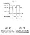
- a second beam is pulse-modulated between high level and base level (including zero level) equal to or lower than the low level in accordance with information, so that an "A-directed (or "non-A-directed") mark is formed to record information (Fig. 3).
- An over write capable medium consists of at least two magnetic layers each having a perpendicular magnetic anisotropy.
- a first layer serves as a recording layer
- a second layer serves as a reference layer.
- the invention of the prior application is divided into first and second aspects.
- the recording medium has a multilayered structure, which is divided into two layers, as shown in Fig. 4A.
- the first layer is the recording layer, which exhibits high coersivity at room temperature and has low reversing temperature.
- the second layer is the reference layer, which exhibits low coersivity at room temperature and has a higher reversing temperature than the first layer. Both the layers comprise perpendicular magnetic layers.
- each of the first and second layers may comprise a multilayered film.
- the coersivity of a first layer is represented by H C1 ; that of a second layer H C2 ; the Curie temperature of the first layer, T C1 ; that of the second layer, T C2 ; the room temperature, T R ; the temperature of the recording medium when a low level laser beam is radiated, T L ; that when a high level laser beam is radiated, T H ; a coupling field applied to the first layer, H D1 ; and a coupling field applied to the second layer, H D2 .
- the recording medium satisfies the following Formula 1, and satisfies Formulas 2 to 5 at the room temperature.
- T R ⁇ T C1 T L ⁇ T C2 ⁇ T H (1) H C1 > H C2 +
- symbol “ ⁇ ” means “equal to” or “substantially equal to”.
- the upper sign corresponds to an A (antiparallel) type medium
- the lower sign corresponds to a P (parallel) type medium (these media will be described later).
- the P type medium includes a ferromagnetic material and a magnetostatic coupling medium.
- the relationship between the coersivity and the temperature is as shown in the graph of Fig. 5. Referring to Fig. 5.
- the thin curve represents the characteristics of the first layer and the bold curve represents those of the second layer.
- an initial field (Hini.) when applied to the recording medium at room temperature, the direction of magnetization of the second layer is reversed without reversing that of the first layer, according to Formula 5.
- the second layer When the initial field (Hini.) is applied to the recording layer before recording, the second layer can be magnetized in the "A direction" (in the drawings, the "A direction” is indicated by an upward arrow, and the "non-A direction” is indicated by a downward arrow). If the initial field (Hini.) is decreased to zero, the direction of magnetization of the second layer can be left unchanged without being re-reversed, according to Formula 4.
- Fig. 4B schematically shows a state wherein only the second layer is magnetized in the "A direction" immediately before recording.
- the direction of magnetization in the first layer represents previously recorded data. Since the direction of magnetization in the first layer 1 does not change the basic operation mechanism, it is indicated by X in the following description.
- the table in Fig. 4B is modified as shown in Condition 1 in Fig. 6 for the sake of simplicity.
- the high-level laser beam is radiated onto the recording meidum to increase the medium temperature to T H . Since T H is high than the Curie temperature T C1 , magnetization of the first layer 1 disappears. In addition, since T H is near the Curie temperature T H2 , magnetization of the second layer 2 also disappears completely or almost completely.
- the bias field (Hb) in the "A direction" or “non-A direction” is applied to the medium in accordance with the type thereof.
- the bias field (Hb) can be a stray field from the medium itself. For the sake of simplicity, assume that the bias field (Hb) in the "non-A direction" is applied to the medium.
- a change in conditions due to high-level laser beam irradiation is called a high-temperature cycle herein.
- Condition 1 in Fig. 7 the low-level laser beam is radiated onto the medium to increase the medium temperature to T L . Since T L is near the Curie temperature T C1 , magnetization of the first layer disapperas completely or almost completely. However, since T L is below the Curie temperature T C2 , magnetization of the second layer does not disappear (condition 2 L in Fig. 7). In Condition 2 L , although the bias field (Hb) is unnecessary, it cannot be turned on or off at high speed. Therefore, the bias field (Hb) is left applied inevitably.
- a change in conditions due to low-level laser beam irradiation is called a low-temperature cycle herein.
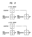
- Fig. 8 summarizes the above descriptions.
- marks, having either "A directional" magnetization or “non-A directional” magnetization, which are opposite to each other, are formed in the high- and low-temperature cycles regardless of the direction of magnetization in the first layer. More specifically, an over-write operation is enabled by pulse modulating the laser beam between high level (high-temperature cycle) and low level (low-temperature cycle) in accordance with data to be recorded.
- the recording medium normally has a disk shape, and is rotated during recording. For this reason, a recorded portion mark is again influenced by the initial field (Hini.) which is applied by initial field apply means during a single rotation. As a result, the direction of magnetization of the second layer is aligned along the original "A direction". However, at the room temperature magnetization of the first layer, and the recorded data can be held.
- initial field Hini.
- a perpendicular magnetic film constituting the first layer and the second layer is selected from the group consisting of (1) crystalline or amorphous ferromagnetic or ferrimagnetic materials having the Curie temperature and no compensation temperature, and (2) crystalline or amorphous ferrimagnetic materials having both the compensation temperature and the Curie temperature.
- the first aspect utilizing the Curie temperature has been described.
- the second aspect of the present invention utilizes decreased coersivity H C at a predetermined temperature exceeding the room temperature.
- the second aspect uses a temperatue T S1 at which the first layer is magnetically coupled to the second layer, in place of the temperature T C1 in the first aspect.
- a temperature T S2 at which the second layer is reversed under the influence of the field Hb is used.
- the second aspect can provide the same effect as in the first aspect.
- the coersivity of the first layer is represented by H C1 : that of the second layer, H C2 ; a temperature at which the first layer is magnetically coupled to the second layer, T S1 ; a temperature at which the direction of magnetization of the second layer is reversed upon influence of the field Hb, T S2 ; room temperature, T R ; a temperature of the medium when a low-level laser beam is applied thereto, T L ; a temperature of the medium when a high-level laser beam is applied thereto; T H , a coupling filed applied to the first layer, H D1 ; and a coupling field applied to the second layer, H D2 .
- the recording medium satisfies the following Formula 6, and satisfies Formulas 7 to 10 at the room temperature.
- upper signs of double signs ⁇ and ⁇ correspond to an A (antiparallel) type medium
- lower signs correspond to a P (parallel) type medium (these media will be descrbed later).
- the recording medium is constituted by the first and second layers, each of the which preferably comprises an amorphous ferrimagnetic material selected from transition metal (e.g., Fe, Co) - heavy rare earth metal (e.g., Gd, Tb, Dy, and the like) alloy compositions.
- transition metal e.g., Fe, Co
- heavy rare earth metal e.g., Gd, Tb, Dy, and the like
- the direction and level of magnetization appearing outside the alloy are determined by the relationship between the direction and level of spin of transition metal atoms (to be referred to as TM hereinafter) and those of heavy rare earth metal atoms (to be referred to as RE hereinafter) inside the alloy.
- TM transition metal atoms
- RE heavy rare earth metal atoms
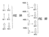
- the direction and level of TM spin are represented by a dotted vector TM-1
- those of RE spin are indicated by a solid vector RE-1
- the direction and level of magnetization of the alloy as a whole are represented by a double-solid vector MA-1.
- the vector MA-1 is represented by a sum of vectors TM-1 and RE-1.
- the vectors TM and RE are directed in the opposite directions due to the mutual effect of the TM spin and the RE spin. Therefore, when these vectors are equal to each other, the sum of vecotrs TM-2 and RE-1 or the sum of vectors TM-2 and RE-1 is zero (i.e., the level of magnetization appearing outside the alloy is zero).
- the alloy composition making the sum of vectors zero is called a compensation composition.
- the alloy the another composition it has a strength equal to a difference between the strengths of both the spins, and has a vector (MA-1 or MA-2) having a direction equal to that of larger vector. Magnetization of this vector appears outside the alloy. For example, as shown in Fig. 9B, a pair of vectors correspond to a vector MA-1 (model 1), and a pair of vectors correspond to a vector MA-2 (model 2).
- the alloy composition is referred to as "XX rich" named after the larger spin name (e.g., RE rich).
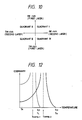
- the first and second layer can be classified into TM rich and RE rich compositions. Therefore, if the composition of the first layer is plotted along the ordinate and that of the second layer is plotted along the abscissa, the types of the recording media according to the present invention can be classified into four quardrants, as shown in Fig. 11.
- the P type medium described previously belongs to Quardrant I and III, and the A type medium belongs to Quadrant II and IV. Referring to Fig. 10, the intersection (origin) of the abscissa and the ordinate represents the compensation composition of both the layers.
- a certain alloy composition has characteristics wherein the coersivity temporarily increases infinitely and then abruptly decreases before a temperature reaches the Curie temperature (at which the coersivity is zero).
- the temperature corresponding to the infinite coersivity is called a compensation temperature (Tcomp.).
- Tcomp. The temperature corresponding to the infinite coersivity.
- No compensation temperature is present between the room temperature and the Curie temperature in the TM rich alloy composition.
- the compensation temperature below the room temperature is nonsense in the magnetooptical recording, and hence, it is assumed in this specification that the compensation temperature is present between the room temperature and the Curie temperature.
- the recording medium in Quadrant I includes all the four types of media.
- the graphs of Figs. 11A to 11D respectively show the relationship between the coersivity and the temperature of the four types of media. Note that thin curves represent characteristics of the first layer and bold curves represent those of second layer.
- the medium No. 1 satisfies Formula 11 : T R ⁇ Tcomp.1 ⁇ T C1 ⁇ T L ⁇ Tcomp.2 ⁇ T C2 ⁇ T H (11)
- the graph of Fig. 12 shows this relation. Note that thin curves indicate the first layer, and bold curves indicate the second layer. Those identifications are same in the following graphs.
- a condition that reverses the direction of magnetization of the reference layer 2 without reversing that of the recording layer 1 by the initial field (Hini.) at the room temperature T R is represented by Formula 12.
- the medium No. 1 satisfies Formula 12 at the T R .
- H C2 coersivity of reference layer 2
- M S1 saturation magnetization of layer 1
- M S2 saturation magnetization of layer 2 t1: film thickness of layer 1 t2: film thickness of layer 2 ⁇ w : interface wall energy
- a condition for the Hini. is represented by Formula 15. If the Hini. disappears, reversed magnetization of the reference layer 2 is influenced by magnetization of the recording layer 1 due to an exchange coupling force.
- the condition that can hold the direction of magnetization of the layer 2 is represented by Formulas 13 and 14.
- the medium No. 1 satisfies Formulas 13 and 14. H C1 > ( ⁇ w /2M S1 t1) (13) H C2 > ( ⁇ w /2M S2 t2) (14) H C2 + ( ⁇ w /2M S2 t2) ⁇
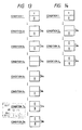
- the layer 2's magnetization of the recording medium which can satisfy Formulas 12 to 14 at the T R is aligned along the "A direction" model 1, in Fig. 9B by the Hini. which satisfies Formula 15. At this time, the recording layer 1 is maintained in the recorded state (Condition 1 in Figs. 13 and 14).
- Condition 1 is held to a point immediately before the recording.
- the bias field (Hb) is applied in the upward direction.
- Condition 1 when the medium temperature is increased to T L upon irradiation of the high-level laser beam, since the temperature T L is substantially equal to the Curie temperature T C1 of the recording layer 1, magnetization of the layer 1 disappears (Condition 2 H ).
- the temperature of the medium increases accordingly.
- the temperature of the medium slightly exceeds the temperature Tcomp.2 of the layer 2
- the relationship between the strengths of the vectors is reversed (from the model 1 to the model 2, in Fig. 9B) although the directions of the RE and TM spins remain the same.
- the direction of magnetization of the layer 2 is reversed to be along the "non-A direction" (Condition 3 H ).
- Condition 4 H when an irradiated portion is separated from the laser beam spot, the temperature of the medium begins to decrease. When the temperature of the medium decreases slightly below the temperature T C2 , magnetization appears in the layer 2. In this case, magnetization of the model 3 of Fig. 9B is generated by Hb (Condition 5 H ). However, since the temperature is yet higher than the temperature T C1 , no magnetization appears in the layer 1.
- Condition 6 H since the temperature of the medium is higher than the temperature T C1 , magnetization of the layer 1 has not yet appeared. In addition, since the coersivity H C2 at this temperature is high, the direction of magnetization of the layer 2 cannot be reversed by the field Hb.
- Condition 8 H the temperature of the medium decreases from the temperature in Condition 8 H to the room temperature. Since the coersivity H C1 at the room temperature is sufficiently high, Condition 8 H is maintained without reversing the direction of magnetization of the layer 1 by the field Hb. In this way, bit formation in the "non-A direction" is completed.
- Condition 1 immediately before recording, the medium temperature is increased to T L upon irradiation of the low-level laser beam. Since the temperature T L is substantially equal to the Curie temperature T C1 of the recording layer 1, magnetization of the layer 1 disappears (Condition 2 L ).
- Condition 2 L when an irradiated portion is separated from the laser beam spot, the medium temperature begins to fall.
- the medium temperature is slightly below the temperature T C1
- the recording layer 1 is influenced by the RE and TM spins (model 1) of the reference layer 2 due to the exchange coupling force.
- the exchange coupling force acts to align each of the RE and TM spins of the layers 1 and 2.
- magnetization of model 2 without regard to the bias field ⁇ Hb, appears in the layer 1 (Condition 3 L ). Since the temperature in Condition 3 L is higher than the temperature Tcomp.1, the TM spin is larger than the RE spin.
- the relationship between the RE and TM spins of the first layer is reversed (from the model 2 to the model 1) in the same manner as in the high-temperature cycle.
- the magnetization of the layer 1 is "A direction" (Condition 4 L ).
- Condition 4 L is maintained even if the medium temperature is decreased to the room temperature. In this way, mark formation in the "A direction" is completed.
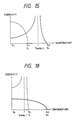
- the medium No. 2 satisfies Formula 16: T R ⁇ T C1 ⁇ T L ⁇ Tcomp.2 ⁇ T C2 ⁇ T H (16)
- the graph of Fig. 15 shows this relation.
- a condition that reverses the direction of magnetization of the layer 2 without reversing that of the layer 1 by the initial field (Hini.) at the room temperature T R is represented by Formula 17.
- the medium No. 2 satisfies Formula 17 at the T R : H C1 > H C2 + ( ⁇ w /2M S1 t1) + ( ⁇ w /2M S2 t2) (17)
- H C1 coersivity of layer 1
- H C2 coersivity of layer 2
- a condition for the Hini. is represented by Formula 20. If the Hini. disappears, reversed magnetization of the layer 2 is influenced by magnetization of the layer 1 due to an exchange coupling force.
- the condition that can hold the direction of magnetization of the layer 2 is represented by Formulas 18 and 19.
- the medium No. 2 satisfies Formulas 18 and 19. H C1 > ( ⁇ w /2M S1 t1) (18) H C2 > ( ⁇ w /2M S2 t2) (19) H C2 + ( ⁇ w /2M S2 t2) ⁇
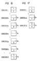
- the layer 2's magnetization of the recording medium which can satisfy Formulas 17 to 19 at the T R is aligned along the "A direction" model 1, in Fig. 9B by the Hini. which satisfies Formula 20. At this time, the layer 1 is maintained in the recorded state (Condition 1 in Figs. 16 and 17).
- Condition 1 is held to a point immediately before the recording.
- the bias field (Hb) is applied in the upward direction.
- Condition 1 when the medium temperature is increased to T L upon irradiation of the high-level laser beam, since the temperature T L is substantially equal to the Curie temperature T C1 of the layer 1, magnetization of the layer 1 disappears (Condition 2 H ).
- the temperature of the medium increases accordingly.
- the temperature of the medium slightly exceeds the temperature Tcomp.2 of the layer 2
- the relationship between the strengths of the vectors is reversed (from the model 1 to the model 2, in Fig. 9B) although the directions of the RE and TM spins remain the same.
- the direction of magnetization of the layer 2 is reversed to the "non-A direction" (Condition 3 H ).
- Condition 4 H when an irradiated portion is separated from the laser beam spot, the temperature of the medium begins to decrease. When the temperature of the medium decreases slightly below the temperature T C2 , magnetization appears in the layer 2. In this case, magnetization of the model 3 is generated by Hb (condition 5 H ). However, since the temperature is yet higher than the temperature T C1 , no magnetization appears in the layer 1.
- Condition 6 H since the temperature of the medium is higher than the temperature T C1 , magnetization of the layer 1 has not yet appeared. In addition, since the coersivity H C2 at this temperature is high, the direction of magnetization of the layer 2 cannot be reversed by the field Hb.
- Condition 7 H the temperature of the medium decreases from the temperature in Condition 7 H to the room temperature. Since the coersivity H C1 at the room temperature is sufficiently high, Condition 7 H is maintained without reversing the direction of magnetization of the layer 1 by the field Hb. In this way, bit formation in the "non-A direction" is completed.
- Condition 1 immediately before recording, the medium temperature is increased to T L upon irradiation of the low-level laser beam. Since the temperature T L is substantially equal to the Curie temperature T C1 of the layer 1, magnetization of the layer 1 disappears (Condition 2 L ).
- Condition 3 L is maintained even if the medium temperature is decreased to the room temperature. As a result, a mark in the "A direction" is formed in the layer 1.
- the medium No. 3 satisfies Formula 21: T R ⁇ Tcomp.1 ⁇ T C1 ⁇ T L ⁇ T C2 ⁇ T H (21)
- the graph of Fig. 18 shows this relation.
- a condition that reverses the direction of magnetization of the layer 2 without reversing that of the layer 1 by the initial field (Hini.) at the room temperature T R is represented by Formula 22.
- the medium No. 3 satisfies Formula 22 at the T R : H C1 > H C2 + ( ⁇ w /2M S1 t1) + ( ⁇ w /2M S2 t2) (22) where H C1 : coersivity of layer 1 H C2 : coersivity of layer 2 M S1 : saturation magnetization of layer 1 M S2 : saturation magnetization of layer 2 t1: film thickness of layer 1 t2: film thickness of layer 2 ⁇ w : interface wall energy
- a condition for the Hini. is represented by Formula 25. If the Hini. disappears, reversed magnetization of the layer 2 is influenced by magnetization of the layer 1 due to an exchange coupling force.
- the condition that can hold the direction of magnetization of the layer 2 is represented by Formulas 23 and 24.
- the medium No. 3 satisfies Formulas 23 and 24.
- the layer 2's magnetization of the recording medium which can satisfy Formulas 22 to 24 at the T R is aligned along the "A direction" (model 1) by the Hini. which satisfies Formula 25. At this time, the layer 1 is maintained in the recorded state (Condition 1 in Figs. 19 and 20).
- Condition 1 is held to a point immediately before the recording.
- the bias field (Hb) is applied in the downward direction.
- Condition 1 when the medium temperature is increased to T L upon irradiation of the high-level laser beam, since the temperature T L is substantially equal to the Curie temperature T C1 of the layer 1, magnetization of the layer 1 disappears (Condition 2 H ).
- Condition 3 H when an irradiated portion is separated from the laser beam spot, the temperature of the medium begins to decrease. When the temperature of the medium decreases slightly below the temperature T C2 , magnetization appears in the layer 2. In this case, magnetization of the model 4 is generated by Hb. However, since the temperature is yet higher than the temperature T C1 , no magnetization appears in the layer 1. This state is Condition 4 H .
- the temperature of the medium decreases from the temperature in Condition 6 H to the room temperature. Since the coersivity H C1 at the room temperature is sufficiently high, magnetization of the layer 1 is stably maintained. In this way, mark formation in the "non-A direction" is completed.
- Condition 1 immediately before recording, the medium temperature is increased to T L upon irradiation of the low-level laser beam. Since the temperature T L is substantially equal to the Curie temperature T C1 of the layer 1, magnetization of the layer 1 disappears. However, at this temperature, since the coersivity H C2 of the layer 2 is sufficiently high, magnetization of the layer 2 will not be reversed by the bias field Hb (Condition 2 L ).
- Condition 2 L when an irradiated portion is separated from the laser beam spot, the medium temperature begins to fall.
- the medium temperature is slightly below the temperature T C1 , the respective spins of the layer 1 are influenced by the RE and TM spins of the layer 2 due to the exchange coupling force.
- the exchange coupling force acts to align each of the RE and TM spins of the layers 1 and 2.
- magnetization of the model 2 of Fig. 9B appears in the layer 1.
- the Tm spin is larger than the RE spin (Condition 3 L ).
- Condition 4 L is maintained even if the medium temperature is decreased to the room temperature. In this way, mark formation in the "A direction" is completed.
- the medium No. 4 satisfies Formula 26: T R ⁇ T C1 ⁇ T L ⁇ T C2 ⁇ T H (26)
- the graph of Fig. 21 shows this relation.
- a condition that reverses the direction of magnetization of the layer 2 without reversing that of the layer 1 by the initial field (Hini.) at the room temperature T R is represented by Formula 27.
- the medium No. 4 satisfies Formula 27 at the T R : H C1 > H C2 + ( ⁇ w /2M S1 t1) + ( ⁇ w /2M S2 t2) (27) where H C1 : coersivity of layer 1 H C2 : coersivity of layer 2 M S1 : saturation magnetization of layer 1 M S2 : saturation magnetization of layer 2 t1 : film thickness of layer 1 t2: film thickness of layer 2 ⁇ w : interface wall enrgy
- a condition for the Hini. is represented by Formula 30. If the Hini. disappears, reversed magnetization of the layer 2 is influenced by magnetization of the layer 1 due to an exchange coupling force.
- the condition that can hold the direction of magnetization of the layer 2 is represented by Formulas 28 and 29.
- the medium No. 4 satisfies Formulas 28 and 29.
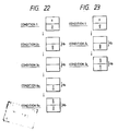
- the layer 2's magnetization of the recording medium which can satisfy Formulas 27 to 29 at the T R is aligned along the "A direction" (model 1) by the Hini. which satisfies Formula 30. At this time, the layer 1 is maintained in the recorded state (Condition 1 in Figs. 22 and 23).
- Condition 1 is held to a point immediately before the recording.
- the bias field (Hb) is applied in the downward direction.
- Condition 3 H when an irradiated portion is separated from the laser beam spot, the temperature of the medium begins to decrease. When the temperature of the medium decreases slightly below the temperature T C2 , magnetization of the layer 2 appears. In this case, magnetization of the model 4 is generated by Hb. However, since the temperature is yet higher than the temperature T C1 , no magnetization appears in the layer 1. This state is Condition 4 H .
- the temperature of the medium decreases from the temperature in Condition 5 H to the room temperature. Since the coersivity H C1 at the room temperature is sufficiently high, magnetization of the layer 1 is stably maintained. In this way, mark formation in the "non-A direction" is completed.
- Condition 1 immediately before recording, the medium temperature is increased to T L upon irradiation of the low-level laser beam. Since the temperature T L exceeds the Curie temperature T C1 of the layer 1, magnetization of the layer 1 disappears. However, at this temperature, since the coersivity H C2 of the layer 2 is sufficiently high, magnetization of the layer 2 will not be reversed by the bias field Hb. This state is Condition 2 L .
- Condition 2 L when an irradiated portion is separated from the laser beam spot, the medium temperature begins to fall.
- the medium temperature is slightly below the temperature T C1 , the respective spins of the recording layer 1 are influenced by the RE and TM spins of the layer 2 due to the exchange coupling force.
- the exchange coupling force acts to align each of the RE and TM spins of the layers 1 and 2.
- magnetization of the model 1, without regard to the bias field ⁇ Hb appears in the layer 1.
- This state is Condition 3 L .
- Condition 3 L is maintained even if the medium temperature is decreased to the room temperature. In this way, mark formation in the "A direction" is completed.
- the medium No. 5 satisfies Formula 31: T R ⁇ Tcomp.1 ⁇ T C1 ⁇ T L ⁇ T C2 ⁇ T H (31)
- the graph of Fig. 24 shows this relation.
- a condition for the Hini. is represented by Formula 35. If the Hini. disappears, reversed magnetization of the layer 2 is influenced by magnetization of the layer 1 due to an exchange coupling force.
- the condition that can hold the direction of magnetization of the layer 2 is represented by Formulas 33 and 34.
- the medium No. 5 satisfies Formulas 33 and 34.
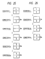
- the layer 2's magnetization of the recording medium which can satisfy Formulas 32 to 34 at the T R is aligned along the "A direction" (model 3) by the Hini. which satisfies Formula 35. At this time, the layer 1 is maintained in the recorded state (Condition 1 in Figs. 25 and 26).
- Condition 3 H when an irradiated portion is separated from the laser beam spot, the temperature of the medium begins to decrease. When the temperature of the medium decreases slightly below the temperature T C2 , magnetization of the layer 2 appears. In this case, magnetization of the model 2 is generated by Hb. However, since the temperature is yet higher than the temperature T C1 , no magnetization appears in the layer 1. This state is Condition 4 H .
- the temperature of the medium decreases from the temperature in Condition 6 H to the room temperature. Since the coersivity H C1 at the room temperature is sufficiently high, magnetization of the layer 1 is stably maintained. In this way, mark formation in the "A direction" is completed.
- Condition 1 immediately before recording, the medium temperature is increased to T L upon irradiation of the low-level laser beam. Since the temperature T L is substantially equal to the Curie temperature T C1 of the layer 1, magnetization of the layer 1 disappears. However, at this temperature, since the coersivity H C2 of the layer 2 is sufficiently high, magnetization of the layer 2 will not be reversed by the bias field Hb (Condition 2 L ).
- the medium temperature begins to fall.
- the respective spins of the recording layer 1 are influenced by the RE and TM spins of the layer 2 due to the exchange coupling force.
- the exchange coupling force acts to align each of the RE and TM spins of the layers 1 and 2.
- magnetization of the model 3 without regard to bias field Hb, appears in the layer 1.
- the TM spin is larger than the RE spin (Condition 3 L ).
- Condition 4 L is maintained even if the medium temperature is decreased to the room temperature. In this way, mark formation in the "non-A direction" is completed.
- the medium No. 6 satisfies Formula 36: T R ⁇ T C1 ⁇ T L ⁇ T C2 ⁇ T H (36)
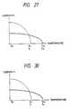
- the graph of Fig. 27 shows this relation.
- a condition that reverses the direction of magnetization of the layer 2 without reversing that of the layer 1 by the initial field (Hini.) at the room temperature T R is represented by Formula 37.
- the medium No. 6 satisfies Formula 37 at the T R : H C1 > H C2 +
- a condition for the Hini. is represented by Formula 40. If the Hini. disappears, reversed magnetization of the layer 2 is influenced by magnetization of the layer 1 due to an exchange coupling force.
- the condition that can hold the direction of magnetization of the layer 2 is represented by Formulas 38 and 39.
- the medium No. 6 satisfies Formulas 38 and 39.
- the layer 2's magnetization of the recording medium which can satisfy Formulas 37 to 39 at the T R is aligned along the "A direction" (model 3) by the Hini. which satisfies Formula 40. At this time, the layer 1 is maintained in the recorded state (Condition 1 in Figs. 28 and 29).
- Condition 1 is held to a point immediately before the recording.
- the bias field (Hb) is applied in the downward direction.
- Condition 3 H when an irradiated portion is separated from the laser beam spot, the temperature of the medium begins to decrease. When the temperature of the medium decreases slightly below the temperature T C2 , magnetization of the layer 2 appears. In this case, magnetization of the model 2 is generated by Hb. However, since the temperature is yet higher than the temperature T C1 , no magnetization appears in the layer 1. This state is Condition 4 H .
- the temperature of the medium decreases from the temperature in Condition 5 H to the room temperature. Since the coersivity H C1 at the room temperature is sufficiently high, magnetization of the layer 1 is stably maintained. In this way, bit formation in the "A direction" is completed.
- Condition 1 immediately before recording, the medium temperature is increased to T L upon irradiation of the low-level laser beam. Since the temperature T L is substantially equal to the Curie temperature T C1 of the layer 1, magnetization of the layer 1 disappears. In this state, however, since the coersivity H C2 of the layer 2 is sufficiently high, magnetization of "A direction" of the layer 2 will not be reversed by the bias field Hb. This state is Condition 2 L .
- Condition 2 L when an irradiated portion is separated from the laser beam spot, the medium temperature begins to fall.
- the medium temperature is slightly below the temperature T C1 , the respective spins of the layer 1 are influenced by the RE and TM spins of the layer 2 due to the exchange coupling force.
- the exchange coupling force acts to align each of the RE and TM spins of the layers 1 and 2.
- magnetization of the model 4 appears in the layer 1.
- This state is Condition 3 L .
- Condition 3 L is maintained even if the medium temperature is decreased to the room temperature. In this way, mark formation in the "non-A direction" is completed.
- the medium No. 7 satisfies Formula 41: T R ⁇ T C1 ⁇ T L ⁇ T C2 ⁇ T H (41)
- the graph of Fig. 30 shows this relation.
- a condition that reverses the direction of magnetization of the layer 2 without reversing that of the layer 1 by the initial field (Hini.) at the room temperature T R is represented by Formula 42.
- the medium No. 7 satisfies Formula 42 at the T R : H C1 > H C2 + ( ⁇ w /2M S1 t1) + ( ⁇ w /2M S2 t2) (42)
- H C1 coersivity of layer 1
- H C2 coersivity of layer 2
- a condition for the Hini. is represented by Formula 45. If the Hini. disappears, reversed magnetization of the layer 2 is influenced by magnetization of the layer 1 due to an exchange coupling force.
- the condition that can hold the direction of magnetization of the layer 2 is represented by Formulas 43 and 44.
- the medium No. 7 satisfies Formulas 43 and 44.
- Condition 1 is held to a point immediately before the recording.
- the base field (Hb) is applied in the downward direction.
- Condition 1 when the medium temperature is increased to T L upon irradiation of the high-level laser beam, since the temperature T L is substantially equal to the Curie temperature T C1 of the layer 1, magnetization of the layer 1 disappears (Condition 2 H ).
- Condition 3 H when an irradiated portion is separated from the laser beam spot, the temperature of the medium begins to decrease. When the temperature of the medium decreases slightly below the temperature T C2 , magnetization of the layer 2 appears. In this case, magnetization of the model 2 is generated by Hb. However, since the temperature is yet higher than the temperature T C1 , no magnetization appears in the layer 1. This state is Condition 4 H .
- the temperature of the medium decreases from the temperature in Condition 5 H to the room temperature. Since the coersivity H C1 at the room temperature is sufficiently high, magnetization of the layer 1 is stably maintained. In this way, bit formation in the "non-A direction" is completed.
- Condition 1 immediately before recording, the medium temperature is increased to T L upon irradiation of the low-level laser beam. Since the temperature T L is substantially equal to the Curie temperature T C1 of the layer 1, magnetization of the layer 1 disappears. In this state, however, since the coersivity H C2 of the layer 2 is sufficiently high, magnetization of "A direction" of the layer 2 will not be reversed by the bias field Hb. This state is Condition 2 L .
- Condition 2 L when an irradiated portion is separated from the laser beam spot, the medium temperature begins to fall.
- the medium temperature is slightly below the temperature T C1 , the respective spins of the layer 1 are influenced by the RE and TM spins of the layer 2 due to the exchange coupling force.
- the exchange coupling force acts to align each of the RE and TM spins of the layers 1 and 2.
- magnetization of the model 3, without regard to the bias field ⁇ Hb appears in the layer 1.
- This state is Condition 3 L .
- Condition 3 L is maintained even if the medium temperature is decreased to the room temperature. In this way, mark formation in the "A direction" is completed.
- the medium No. 8 satisfies Formula 46: T R ⁇ T C1 ⁇ T L ⁇ Tcomp.2 ⁇ T C2 ⁇ T H (46)
- the graph of Fig. 33 shows this relation.
- a condition that reverses the direction of magnetization of the layer 2 without reversing that of the layer 1 by the initial field (Hini.) at the room temperature T R is represented by Formula 47.
- the medium No. 8 satisfies Formula 47 at the T R : H C1 > H C2 +
- a condition for the Hini. is represented by Formula 50. If the Hini. disappears, reversed magnetization of the layer 2 is influenced by magnetization of the layer 1 due to an exchange coupling force.
- the condition that can hold the direction of magnetization of the layer 2 is represented by Formulas 48 and 49.
- the medium No. 8 satisfies Formulas 48 and 49.
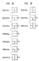
- the layer 2's magnetization of the recording medium which can satisfy Formulas 47 to 49 at the T R is aligned along the "A direction" (model 1) by the Hini. Which satisfies Formula 50. At this time the layer 1 is maintained in the recorded state (Condition 1 in Figs. 34 and 35).
- Condition 1 is held to a point immediately before the recording.
- the bias field (Hb) is applied in the upward direction.
- Condition 1 when the medium temperature is increased to T L upon irradiation of the high-level laser beam, since the temperature T L is substantially equal to the Curie temperature T C1 of the layer 1, magnetization of the layer 1 disappears (Condition 2 H ).
- Condition 4 H when an irradiated portion is separated from the laser beam spot, the temperature of the medium begins to decrease. When the temperature of the medium decreases slightly below the temperature T C2 , magnetization of the layer 2 appears. In this case, magnetization of the model 3 is generated by Hb. However, since the temperature is yet higher than the temperature T C1 , no magnetization appears in the layer 1. This state is Condition 5 H .
- magnetization When the medium temperature further decreases slightly below the temperature T C1 , magnetization also appears in the layer 1. At this time, magnetization (model 4) of the layer 1 influences the layer 1 due to the exchange coupling force to align each of the RE and TM spins of the layers 1 and 2. For this reason, magnetization of the model 3 appears in the layer 1 (Condition 7 H ).
- the temperature of the medium decreases from the temperature in Condition 7 H to the room temperature. Since the coersivity H C1 at the room temperature is sufficiently high, magnetization of the layer 1 is stably maintained. In this way, mark formation in the "A direction" is completed.
- Condition 1 immediately before recording, the medium temperature is increased to T L upon irradiation of the low-level laser beam. Since the temperature T L is substantially equal to the Curie temperature T C1 of the layer 1, magnetization of the layer 1 disappears. In this state, however, since the coersivity H C2 of the layer 2 is sufficiently high, magnetization of the layer 2 will not be reversed by the bias field Hb (Condition 2L).
- Condition 2 L when an irradiated portion is separated from the laser beam spot, the medium temperature begins to fall. When the medium temperature begins to fall. When the medium temperature is slightly below the temperature T C1 , the respective spins of the layer 1 are influenced by the RE and TM spins of the layer 2 due to the exchange coupling force. In other words, the exchange coupling force acts to align each of the RE and TM spins of the layers 1 and 2. As a result, magnetization of the model 2, without regard to the bias field Hb, appears in the layer 1. This state is Condition 3 L .
- Condition 3 L is maintained even if the medium temperature is decreased to the room temperature. In this way, mark formation in the "non-A direction" is completed.
- the medium No. 9 satisfies Formula 51: T R ⁇ T C1 ⁇ T L ⁇ T C2 ⁇ T H (51)
- the graph of Fig. 36 shows this relation.
- a condition that reverses the direction of magnetization of the layer 2 without reversing that of the layer 1 by the initial field (Hini.) at the room temperature T R is represented by Formula 52.
- the medium No. 9 satisfies Formula 52 at the T R : H C1 > H C2 +
- H C1 coersivity of layer 1 H C2 : coersivity of layer 2 M S1 : saturation magnetization of layer 1 M S2 : saturation magnetization of layer 2 t1: film thickness of layer 1 t2: film thickness of layer 2 ⁇ w : interface wall energy
- a condition for the Hini. is represented by Formula 50. If the Hini. disappears, reversed magnetization of the layer 2 is influenced by magnetization of the layer 1 due to an exchange coupling force.
- the condition that can hold the direction of magnetization of the layer 2 is represented by Formulas 53 and 54.
- the medium No. 9 satisfies Formulas 53 and 54.
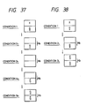
- the layer 2's magnetization of the recording medium which can satisfy Formulas 52 to 54 at the T R is aligned along the "A direction" (model 1) by the Hini. which satisfies Formula 55. At this time, the layer 1 is maintained in the recorded state (Condition 1 in Figs. 37 and 38).
- Condition 1 is held to a point immediately before the recording.
- the bias field (Hb) is applied in the downward direction.
- Condition 1 when the medium temperature is increased to T L upon irradiation of the high-level laser beam, since the temperature T L is substantially equal to the Curie temperature T C1 of the layer 1, magnetization of the layer 1 disappears (Condition 2 H ).
- Condition 3 H when an irradiated portion is separated from the laser beam spot, the temperature of the medium begins to decrease. When the temperature of the medium decreases slightly below the temperature T C2 , magnetization of the layer 2 appears. In this case, magnetization of the model 4 is generated by Hb. However, since the temperature is yet higher than the temperature T C1 , no magnetization appears in the layer 1. This state is Condition 4 H .
- the temperature of the medium decreases from the temperature in Condition 5 H to the room temperature. Since the coersivity H C1 at the room temperature is sufficiently high, magnetization of the layer 1 is stably maintained. In this way, mark formation in the "A direction" is completed.
- Condition 1 immediately before recording the medium temperature is increased to T L upon irradiation of the low-level laser beam. Since the temperature T L is substantially equal to the Curie temperature T C1 of the layer 1, magnetization of the layer 1 disappears. In this state, however, since the coersivity H C2 of the layer 2 is sufficiently high, magnetization of "A direction" of the layer 2 will not be reversed by the bias field Hb. This state is Condition 2 L .
- Condition 2 L when an irradiated portion is separated from the laser beam spot, the medium temperature begins to fall.
- the medium temperature is slightly below the temperature T C1 , the recording layer 1 is influenced by the RE and TM spins of the layer 2 due to the exchange coupling force.
- the exchange coupling force acts to align each of the RE and TM spins of the layers 1 and 2.
- magnetization of the model 2 appears in the layer 1.
- This state is Condition 3 L .
- Condition 3 L is maintained even if the medium temperature is decreased to the room temperature. In this way, mark formation in the "non-A direction" is completed.
- An over write capable medium must satisfy the following relation so that information in the first layer is not erased by the magnetization of the initialized second layer:
- the medium must also satisfy the following relation so that the magnetization of the initialized second layer is not reversed by the magnetization of the first layer: Therefore, when the exchange coupling force ⁇ w is too large, since a coercivity H C and a saturated magnetic moment M s are determined by the material of the magnetic layer, the film thickness t must be increased.
- the film thickness of the first layer is decreased too much (e.g., 400 ⁇ or less), if information is reproduced therefrom, a Kerr rotation angle ⁇ k is decreased, and hence, a C/N ratio is decreased.
- the thickness of the second layer should be decreased as much as possible.
- the thickness of the second layer can be about 100 ⁇ .
- the present inventors have made studies to attain a decrease in film thickness of the second layer while the film thickness of the first layer remains the same, or so as to exceed an increase in film thickness of the first layer even if the thickness of the first layer is increased.
- the present invention made further studies, and found that when the non-magnetic element was doped, the exchange coupling force ⁇ w was decreased, and at the same time, the H C M S product of the first layer was also decreased.
- a medium having a larger H C M S product H C1 M S1 of the first layer than a H C M S product H C2 M S2 of the second layer is selected, so that the exchange coupling force ⁇ w is decreased by doping a non-magnetic element in the first layer to decrease the film thickness t2 of the second layer, and the total film thickness t12 is consequently decreased.
- a magnetic moment of a magnetic body is defined by an orbital angular momentum and a spin angular momentum of an outer shell electron of an atom, and its exchange interaction is performed by the electron and an electron adjacent thereto according to the Pauli principle and an electrostatic interaction between the two electrons. For this reason, when a distance between magnetic atoms is increased or the number of most adjacent magnetic atoms is decreased, a degree of overlapping of wave functions of electrons of the atom is decreased, resulting in a decrease in exchange interaction.
- a distance between magnetic atoms in layers can be essentially increased, and the number of most adjacent magnetic atoms is decreased.
- the exchange interaction is decreased to decrease the exchange coupling force ⁇ w .
- Non-magnetic elements to be used include, e.g., Si, Ge, Ti, Cr, Cu, In, and the like.
- a doping amount of the non-magnetic element is preferably at least 0.5 atm% to obtain the above effect.
- an actual doping amount should be obtained by preliminary experiments in accordance with a predetermined exchange coupling force ⁇ w and an H C M S product at that time.
- the doping amount is at most 10 atm%, and is generally smaller than 5 atm%.
- a three-element RF magnetron sputtering apparatus was used, and a disk-like glass substrate having a thickness of 1.2 mm and a diameter of 200 mm was set in a vacuum chamber of the apparatus.
- the interior of the vacuum chamber was temporarily evacuated to 5 x 10 ⁇ 5 Pa. Thereafter, argon (Ar) gas was introduced into the chamber, and sputtering was performed at a film formation rate of about 3 ⁇ /sec while maintaining the Ar gas pressure to be 2 x 10 ⁇ 1 Pa.
- Ar argon
- Fig. 4A several types of two-layered magnetooptical recording media (Fig. 4A) were prepared by changing an electric power to be applied to a Ti target to change an amount of Ti to be doped in the first layer.
- the H C M S product of the first layer was 600,000, and that of the second layer was 200,000.
- the H C M S product of the first layer is larger than that of the second layer.
- Fig. 39 is a graph showing the calculation results. Fig. 39 also shows a change in minimum total film thickness t12 by an alternate long and a short dashed line on the basis of the graph of the film thicknesses t1 and t2.
- the total film thickness t12 can be decreased.
- the H C M S product of the first layer was 150,000, and that of the second layer was 200,000. In this case, the H C M S product of the first layer is smaller than that of the second layer.
- Fig. 40 is a graph showing the calculation results. Fig. 40 also shows a change in minimum total film thickness t12 by an alternate long and a short dashed line on the basis of the graph of the film thicknesses t1 and t2.
- a medium having a larger H C M S product of the first layer than that of the second layer is selected, and a non-magnetic element is doped in the first layer to decrease the exchange coupling force ⁇ w .
- the total film thickness t12 can be decreased without decreasing the film thickness t1 of the first layer, i.e., decreasing the C/N ratio.
Applications Claiming Priority (2)
| Application Number | Priority Date | Filing Date | Title |
|---|---|---|---|
| JP1043562A JPH02223041A (ja) | 1989-02-23 | 1989-02-23 | 磁性層間の交換結合力が制御されたオーバーライト可能な光磁気記録媒体 |
| JP43562/89 | 1989-02-23 |
Publications (2)
| Publication Number | Publication Date |
|---|---|
| EP0384746A2 true EP0384746A2 (fr) | 1990-08-29 |
| EP0384746A3 EP0384746A3 (fr) | 1991-12-11 |
Family
ID=12667186
Family Applications (1)
| Application Number | Title | Priority Date | Filing Date |
|---|---|---|---|
| EP19900301894 Withdrawn EP0384746A3 (fr) | 1989-02-23 | 1990-02-21 | Milieu d'enregistrement magnéto-optique pouvant être surécrit |
Country Status (3)
| Country | Link |
|---|---|
| US (1) | US5106704A (fr) |
| EP (1) | EP0384746A3 (fr) |
| JP (1) | JPH02223041A (fr) |
Cited By (1)
| Publication number | Priority date | Publication date | Assignee | Title |
|---|---|---|---|---|
| EP0428128B1 (fr) * | 1989-11-13 | 1999-02-03 | Hitachi, Ltd. | Support d'enregistrement magnéto-optique |
Families Citing this family (3)
| Publication number | Priority date | Publication date | Assignee | Title |
|---|---|---|---|---|
| JP3038735B2 (ja) * | 1989-11-01 | 2000-05-08 | 株式会社ニコン | オーバライト可能な光磁気記録媒体及び前処理方法 |
| JP3509031B2 (ja) * | 1993-12-10 | 2004-03-22 | 片山特殊工業株式会社 | リード付き金属多孔体の製造方法及び該方法により製造されたリード付き金属多孔体 |
| JPH07169123A (ja) * | 1993-12-16 | 1995-07-04 | Nikon Corp | オーバーライト可能な光磁気記録媒体 |
Family Cites Families (6)
| Publication number | Priority date | Publication date | Assignee | Title |
|---|---|---|---|---|
| JPS5778652A (en) * | 1980-11-01 | 1982-05-17 | Daido Steel Co Ltd | Thermal magnetic recording carrier and thermal magnetic recording system |
| JP2521908B2 (ja) * | 1985-06-11 | 1996-08-07 | 株式会社ニコン | オ―バ―ライト可能な光磁気記録方法、それに使用される光磁気記録装置及び光磁気記録媒体、並びに変調方法、変調装置及び光磁気記録媒体 |
| US4871614A (en) * | 1986-07-09 | 1989-10-03 | Canon Kabushiki Kaisha | Opto-magnetic recording medium having three exchange-coupled magnetic layers |
| CA1322408C (fr) * | 1986-08-20 | 1993-09-21 | Tomiji Tanaka | Methode d'enregistrement thermagnetique utilisant un laser module en puissance pour balayer une structure a deux couches couplees magnetiquement |
| JP2570270B2 (ja) * | 1986-10-08 | 1997-01-08 | 株式会社ニコン | ツービームによる光磁気記録方法及び装置 |
| DE3852329T2 (de) * | 1987-03-13 | 1995-08-03 | Canon Kk | Magneto-optisches Aufzeichnungsmedium und Verfahren. |
-
1989
- 1989-02-23 JP JP1043562A patent/JPH02223041A/ja active Pending
-
1990
- 1990-02-20 US US07/481,203 patent/US5106704A/en not_active Expired - Fee Related
- 1990-02-21 EP EP19900301894 patent/EP0384746A3/fr not_active Withdrawn
Cited By (1)
| Publication number | Priority date | Publication date | Assignee | Title |
|---|---|---|---|---|
| EP0428128B1 (fr) * | 1989-11-13 | 1999-02-03 | Hitachi, Ltd. | Support d'enregistrement magnéto-optique |
Also Published As
| Publication number | Publication date |
|---|---|
| JPH02223041A (ja) | 1990-09-05 |
| US5106704A (en) | 1992-04-21 |
| EP0384746A3 (fr) | 1991-12-11 |
Similar Documents
| Publication | Publication Date | Title |
|---|---|---|
| USRE35630E (en) | Over write capable magnetooptical recording medium, recording method and apparatus using the same | |
| US4855975A (en) | Over write capable magnetooptical recording method using two beams, and magnetooptical recording apparatus therefor | |
| EP0225141B1 (fr) | Milieu d'enregistrement magnéto-optique | |
| US5239524A (en) | Over write capable magnetooptical recording method, and magnetooptical recording apparatus and medium used therefor | |
| EP0475446B1 (fr) | Milieu d'enregistrement magnéto-optique susceptible de sur-enregistrement et permettant une marge de l'intensité de rayon de niveau haut élargie | |
| US5164926A (en) | Over-write capable magnetooptical recording medium with four magnetic layered structure dispensing with external initializing field | |
| US5475657A (en) | Overwrite capable magnetooptial recording apparatus | |
| US5343449A (en) | Over-write capable magnetooptical recording medium having reading layer | |
| US5239534A (en) | Multi-layer over write capable magnetooptical recording medium | |
| EP0451297B1 (fr) | Pretraitement d'un support d'enregistrement opto-magnetique reinscriptible et support d'enregistrement opto-magnetique reinscriptible pretraite | |
| US5645911A (en) | Over-writable method of magnetooptical recording | |
| US5191564A (en) | Over-write capable magnetooptical recording medium having groove depth of 800 Å or less | |
| EP0384746A2 (fr) | Milieu d'enregistrement magnéto-optique pouvant être surécrit | |
| US5014252A (en) | Over write capable magnetooptical recording method using two beams, and magnetooptical recording apparatus therefor | |
| US5367507A (en) | Over write capable magnetooptical recording method, and magnetooptical recording apparatus and medium used therefor | |
| US5240784A (en) | Magnetooptical recording medium | |
| EP0385786B1 (fr) | Milieu d'enregistrement magnéto-optique | |
| US5440531A (en) | Magneto-optical reproducing method | |
| US5389455A (en) | Over-write capable magnetooptical recording medium having C/N ratio exceeding 53 dB | |
| EP0474505A2 (fr) | Cassette pour un milieu d'enregistrement magnéto-optique | |
| EP0373898B1 (fr) | Milieu d'enregistrement magnéto-optique avec capacité de sur-inscription | |
| EP0420587B1 (fr) | Milieu magnéto-optique capable de surinscription | |
| JP2535952B2 (ja) | 磁性層間の交換結合力が制御された多層光磁気記録媒体 | |
| EP0450237B1 (fr) | Support d'enregistrement magnétooptique surinscriptible à faible force de couplage d'échange | |
| JPH0816993B2 (ja) | 転写層を有するオーバーライト可能な光磁気記録媒体 |
Legal Events
| Date | Code | Title | Description |
|---|---|---|---|
| PUAI | Public reference made under article 153(3) epc to a published international application that has entered the european phase |
Free format text: ORIGINAL CODE: 0009012 |
|
| AK | Designated contracting states |
Kind code of ref document: A2 Designated state(s): DE FR GB IT |
|
| PUAL | Search report despatched |
Free format text: ORIGINAL CODE: 0009013 |
|
| AK | Designated contracting states |
Kind code of ref document: A3 Designated state(s): DE FR GB IT |
|
| STAA | Information on the status of an ep patent application or granted ep patent |
Free format text: STATUS: THE APPLICATION IS DEEMED TO BE WITHDRAWN |
|
| 18D | Application deemed to be withdrawn |
Effective date: 19920612 |