EP0384805A1 - Oszillierender Mechanismus mit genauen Endanschlägen - Google Patents
Oszillierender Mechanismus mit genauen Endanschlägen Download PDFInfo
- Publication number
- EP0384805A1 EP0384805A1 EP90400384A EP90400384A EP0384805A1 EP 0384805 A1 EP0384805 A1 EP 0384805A1 EP 90400384 A EP90400384 A EP 90400384A EP 90400384 A EP90400384 A EP 90400384A EP 0384805 A1 EP0384805 A1 EP 0384805A1
- Authority
- EP
- European Patent Office
- Prior art keywords
- stop
- finger
- shaft
- motor
- lever arm
- Prior art date
- Legal status (The legal status is an assumption and is not a legal conclusion. Google has not performed a legal analysis and makes no representation as to the accuracy of the status listed.)
- Withdrawn
Links
- 230000033001 locomotion Effects 0.000 claims description 22
- 238000013016 damping Methods 0.000 claims description 4
- 230000001131 transforming effect Effects 0.000 claims description 2
- 230000010355 oscillation Effects 0.000 description 5
- 230000000694 effects Effects 0.000 description 3
- 230000005540 biological transmission Effects 0.000 description 2
- 239000003638 chemical reducing agent Substances 0.000 description 1
- 229920001971 elastomer Polymers 0.000 description 1
- 239000000806 elastomer Substances 0.000 description 1
- 230000001681 protective effect Effects 0.000 description 1
Images

Classifications
-
- F—MECHANICAL ENGINEERING; LIGHTING; HEATING; WEAPONS; BLASTING
- F16—ENGINEERING ELEMENTS AND UNITS; GENERAL MEASURES FOR PRODUCING AND MAINTAINING EFFECTIVE FUNCTIONING OF MACHINES OR INSTALLATIONS; THERMAL INSULATION IN GENERAL
- F16H—GEARING
- F16H21/00—Gearings comprising primarily only links or levers, with or without slides
- F16H21/10—Gearings comprising primarily only links or levers, with or without slides all movement being in, or parallel to, a single plane
- F16H21/44—Gearings comprising primarily only links or levers, with or without slides all movement being in, or parallel to, a single plane for conveying or interconverting oscillating or reciprocating motions
Definitions
- the invention relates to a mechanism for transmitting an alternating circular movement from a first shaft to a second shaft, this second shaft being driven to also perform an alternating circular movement; this mechanism has precise stop limits at the ends of the travel of the first shaft and, for a travel of a determined value of this tree, there is a firm immobilization of the second tree by the first tree as long as the latter n is not set in motion.
- this mechanism comprises, on the first shaft, a lever arm extending radially and provided at its free end with a finger parallel to this first shaft; on the second shaft is wedged a crank arm extending radially and having a slot elongated in the radial direction in which the finger associated with the first shaft is freely engaged.
- the alternating oscillations of the first shaft are transmitted by the finger to the crank arm in which this finger can slide during the alternating movements of the first shaft, and these oscillations are finally transmitted to the second shaft.
- the direction of transmission of the movement can be reversed if desired, the oscillations of the second shaft then causing the first shaft to oscillate.
- This known mechanism is designed only for the uninterrupted transmission of an alternating circular movement.
- the stopping of the motor shaft does indeed result in the stopping of the movement, but this stopping does not take place at a defined relative position of the two shafts; at the time of stopping, the crank arm and the lever arm form an arbitrary angle between them which is not repeated at each stop.
- the crank arm and the lever arm form an arbitrary angle between them which is not repeated at each stop.
- the main purpose of the invention is to achieve a mechanism of the type described above perfected in such a way that the motor shaft stops at a precise position at the ends of its alternative stroke; according to a secondary object of the invention, when this alternative stroke of the drive shaft is 270 °, the stopping of the drive shaft is accompanied by a firm immobilization in rotation of the shaft driven by this drive shaft .
- the main object of the invention is achieved when, in a mechanism comprising on a drive shaft a radial lever arm provided at its free end with a finger directed parallel to this drive shaft, on a driven shaft a radial crank arm having a radial elongated slot in which the finger associated with the drive shaft is engaged in sliding action, the latter being coupled to a drive member for performing alternative circular strokes of amplitude less than 360 °, according to the invention it is provided in the elongated slot a solidly fixed stop to positively stop the sliding finger in this slot exactly at the end of the circular stroke of the motor shaft, at the same time as a means of cutting off the energy supply of this motor member in relation to the position of the same motor shaft approaching said end of its travel.
- the driven shaft drives in its movements an element with great inertia
- a means of braking or damping of the movement arranged to act on the mechanism in the direction of just deceleration. before the stop meets the finger.
- the secondary purpose mentioned above is achieved with a mechanism as defined above when at at least one of the two limit switches of the motor shaft, the lever arm is stopped by the contact of the finger and the stop at a position at which it is perpendicular to the crank arm At this position the driven shaft can no longer rotate in one direction or in the opposite direction, it is immobilized firmly in rotation tion, subject to the play necessary for the sliding of the finger in the elongated slot.
- the alternating circular strokes of the two shafts and of the two arms are carried out symmetrically on either side of the plane passing through the geometric axes of these two shafts; in addition, preferably the two shafts are parallel to each other and separated by a distance L.
- the same stop firmly fixed in the elongated slot serves to stop the finger associated with the motor shaft, with precision, at each of the two limit switches of each movement of the motor shaft.
- the embodiment described here is particular in the sense that the mechanism of the invention is incorporated into an apparatus the function of which is to present a vertical table of large dimensions alternately at two positions located at 90 ° with respect to the other, with a time predetermined stop time and adjustable duration at each of these two positions, these durations can be identical or different.
- This table can be, for example, a target for shooting, a poster or information poster support, a display of items offered for sale, etc.
- mechanism includes the use of all the features provided by the invention.
- a supporting frame 1 protected by a general external envelope 2 carries as an engine member an electric motor 3 supplied with electric current from a storage battery 4 sheltered by the general envelope 2; between the battery 4 and and the motor 3 is an electrical circuit (not shown) for command, control and adjustment, known per se.
- the electric motor 3 is completed by a speed reducer 5 which has an output shaft 6 arranged vertically in the position of use of the device.
- This shaft 6 is the driving shaft of the mechanism of the invention; it carries a lever arm 7 which is locked therein in rotation by one of its ends and which extends radially in a horizontal plane to carry at its free end a vertical finger 8.
- This finger 8 is engaged, so as to being able to slide there freely, in an elongated slot provided in a crank arm 9 disposed in a horizontal plane.
- this crank arm 9 is produced as a tuning fork, with two parallel branches limiting between them an elongated slot 10.
- crank arm 10 extends radially relative to a shaft 11 on which it is locked in rotation in one of its end parts.
- This shaft 11 is arranged vertically in the position of use of the device and guided in a bearing 12 carried by the frame 1.
- the shaft 11 is the driven shaft of the device of the invention; it has an upper end protruding above the general envelope 2. In this upper end part is provided a diametrical notch 13 in which it is possible to engage and fix a table or a panel or the like not shown) to oscillate.
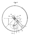
- the motor shaft 6 and the driven shaft 11 are parallel, spaced by a distance L between their geometric axes; the oscillations of the motor shaft 8 and, consequently, those of the driven shaft 8 are symmetrically on either side of the vertical plane, indicated in Figure 3 by a dashed line 14, which passes through the geometric axes of the two trees 6, 7.
- the motor shaft 6 performs a reciprocating circular movement under the control of a microprocessor (not shown) suitably programmed to trigger the power supply to the electric motor 3 at the desired time and in the desired direction, after a predetermined stop period. and adjustable, at each stop position, that is to say at each limit switch. It is therefore easy to understand that the amplitude of the alternative travel and the symmetrical situation or not of the ends of the travel can be chosen at will, according to the conditions envisaged for using the device equipped with the mechanism of the invention.
- the reciprocating circular movement of the motor shaft 6 and, therefore, of the lever arm 7, has an amplitude of 270 °, as indicated by a double arrow F in FIG. 3.
- a single stop 15 firmly fixed to the crank arm 9 inside the slot 10 can serve as a positive means of stopping the movement at each of the two limit switches of the finger 8 sliding in the slot 10.
- the useful length of the lever arm 7, between the geometric axis of the drive shaft 6 and the geometric axis of the finger 8, is equal to L / ⁇ 2, as is the distance existing between the geometric axis of the driven shaft 11 and the geometric axis of the finger 8 when the latter is applied against the stop 15, it follows that, at each of the stop positions at the end of the stroke, as shown in FIG. 3 for the only one of these positions, the lever arm 7 is perpendicular to the crank arm 9. The latter is therefore positively immobilized in rotation with the driven shaft 11, and with the table or panel or the like object fixed to the latter , apart from the operating clearance which is provided for the sliding of the finger 8 inside the elongated slot 10.
- a plate 16 (shown in FIG. 1 only) is fixed on the upper edge of the two parallel branches of the crank arm 9 so as to operate the movable element of an end-of-travel microswitch 17 fixed properly to the bearing 12 There are two symmetrically arranged limit switches.
- each of the microswitches 17 causes the generation of a signal which triggers the stopping of the electrical supply of the motor 3, the counting of a stopping time, the reversal of the direction of supply motor 3 so that, at the end of the stop time, motor 3 turns in the opposite direction.
- Other equivalent means could be used to perform these functions.
- Each microswitch 17 is placed in an advanced position relative to the instant of contact between the finger 8 and the stop 15 so that the reduction gear 5 and the motor 3 no longer supply motor torque before the end of the stroke and produce a slowing motion effect.
- the adjustment of the instant of operation of the microswitch 17 may be sufficient to provide a deceleration such that the finger 8 "comes to die” against the stop 15 just at the end of the stroke, which avoids any rebound.
- crank arm 9 extends beyond the driven shaft 11 and a block 18 (FIGS. 2 and 3), elastically deformable, of elastomer, is fixed there firmly.
- This block 18 has a projecting end portion intended to meet, at each end of the race, a stop 19A, 19B.
- stops 19A, 19B could themselves be elastically deformable and placed to be encountered directly by one or the other of the two arms 7 or 9 arriving at the end of its travel. It would also be possible to provide an elastically erasable element on the abutment 15 by being encountered by the finger 8 before the latter is positively stopped by the rigid body of this abutment 15.
- the driven shaft 11 performs oscillations of an amplitude of 90 ° between two extreme positions at each of which it is firmly immobilized in rotation by the lever arm 7 which is then perpendicular to the crank arm 9 at the end of each of its strokes, the amplitude of which is 270 °.
Landscapes
- Engineering & Computer Science (AREA)
- General Engineering & Computer Science (AREA)
- Mechanical Engineering (AREA)
- Transmission Devices (AREA)
Applications Claiming Priority (2)
| Application Number | Priority Date | Filing Date | Title |
|---|---|---|---|
| FR8902283A FR2643436B1 (fr) | 1989-02-22 | 1989-02-22 | Mecanisme a mouvements circulaires alternatifs et a limites precises d'arret |
| FR8902283 | 1989-02-22 |
Publications (1)
| Publication Number | Publication Date |
|---|---|
| EP0384805A1 true EP0384805A1 (de) | 1990-08-29 |
Family
ID=9379009
Family Applications (1)
| Application Number | Title | Priority Date | Filing Date |
|---|---|---|---|
| EP90400384A Withdrawn EP0384805A1 (de) | 1989-02-22 | 1990-02-13 | Oszillierender Mechanismus mit genauen Endanschlägen |
Country Status (2)
| Country | Link |
|---|---|
| EP (1) | EP0384805A1 (de) |
| FR (1) | FR2643436B1 (de) |
Cited By (1)
| Publication number | Priority date | Publication date | Assignee | Title |
|---|---|---|---|---|
| EP1710473A1 (de) * | 2005-02-22 | 2006-10-11 | BorgWarner Inc. | Gestängeanordnung mit zwei Hebeln mit einem Schmutz entfernenden Element |
Citations (1)
| Publication number | Priority date | Publication date | Assignee | Title |
|---|---|---|---|---|
| DE458676C (de) * | 1926-11-17 | 1928-04-17 | Max Loesch Maschinenfabrik | Getriebe mit zwei um feste Punkte drehbar gelagerten Hebeln |
-
1989
- 1989-02-22 FR FR8902283A patent/FR2643436B1/fr not_active Expired - Fee Related
-
1990
- 1990-02-13 EP EP90400384A patent/EP0384805A1/de not_active Withdrawn
Patent Citations (1)
| Publication number | Priority date | Publication date | Assignee | Title |
|---|---|---|---|---|
| DE458676C (de) * | 1926-11-17 | 1928-04-17 | Max Loesch Maschinenfabrik | Getriebe mit zwei um feste Punkte drehbar gelagerten Hebeln |
Non-Patent Citations (1)
| Title |
|---|
| LA MACHINE MODERNE, vol. 57, no. 657, décembre 1963, page 48; P.W. JENSEN: "Une tringlerie simple remplace trois engrenages" * |
Cited By (2)
| Publication number | Priority date | Publication date | Assignee | Title |
|---|---|---|---|---|
| EP1710473A1 (de) * | 2005-02-22 | 2006-10-11 | BorgWarner Inc. | Gestängeanordnung mit zwei Hebeln mit einem Schmutz entfernenden Element |
| CN1824972B (zh) * | 2005-02-22 | 2010-05-26 | 博格华纳公司 | 连杆组件和具有连杆组件的控制机构 |
Also Published As
| Publication number | Publication date |
|---|---|
| FR2643436A1 (fr) | 1990-08-24 |
| FR2643436B1 (fr) | 1991-05-03 |
Similar Documents
| Publication | Publication Date | Title |
|---|---|---|
| EP0076268B1 (de) | Automatischer manipulator | |
| US8786153B2 (en) | Kinetic energy accumulator and an energy transfer system incorporating a kinetic energy accumulator | |
| FR2493202A1 (fr) | Outil portatif de percage a moteur | |
| FR2925210A1 (fr) | Commande compacte pour appareillage electrique moyennes et hautes tensions | |
| EP0427641B1 (de) | Fernsteuerungsvorrichtung für einen elektrischen Schutzschalter | |
| CH643667A5 (fr) | Appareil de balayage pour photocopieur. | |
| FR2698658A1 (fr) | Dispositif d'actionnement automatique pour porte coulissante, notamment pour véhicule automobile. | |
| FR2546454A1 (fr) | Vehicule de travail autopropulse | |
| FR2643436A1 (fr) | Mecanisme a mouvements circulaires alternatifs et a limites precises d'arret | |
| EP0069032B1 (de) | Sicherheitsbremsvorrichtung, eingesetzt zwischen einer Antriebswelle und einem rotierenden Arbeitsteil | |
| EP2359716A1 (de) | Vorrichtung zum Öffnen einer Schublade eines Möbelstücks oder Ähnlichem | |
| EP0337864B1 (de) | Brillengestell-Träger für eine Reproduzier-Maschine | |
| FR2819558A1 (fr) | Moteur fonctionnant par gravite | |
| EP1267104B1 (de) | Interne Steuervorrichtung für mechanisches Wechselgetriebe | |
| CA1048071A (fr) | Distributeur automatique de cartes de jeux et d'autres usages | |
| EP0002092B1 (de) | Gemüseschneidemaschine | |
| EP0030061A2 (de) | Brotschneidemaschine | |
| CH339100A (fr) | Dispositif de trancanage à pas et course réglables pour bobinoir | |
| BE568324A (de) | ||
| EP2891822A9 (de) | Leistungsübertragungsvorrichtung | |
| FR2615480A3 (fr) | Dispositif de commutation de circuit pour machine de cerclage | |
| CH347564A (fr) | Récepteur pour installations de télécommande | |
| BE494242A (de) | ||
| FR2486613A1 (fr) | Dispositif pour convertir une force centrifuge en une force et un mouvement lineaires | |
| FR3108301A1 (fr) | Détecteur ferroviaire à temporisateur mécanique |
Legal Events
| Date | Code | Title | Description |
|---|---|---|---|
| PUAI | Public reference made under article 153(3) epc to a published international application that has entered the european phase |
Free format text: ORIGINAL CODE: 0009012 |
|
| 17P | Request for examination filed |
Effective date: 19900215 |
|
| AK | Designated contracting states |
Kind code of ref document: A1 Designated state(s): BE CH DE ES GB IT LI |
|
| 17Q | First examination report despatched |
Effective date: 19910925 |
|
| STAA | Information on the status of an ep patent application or granted ep patent |
Free format text: STATUS: THE APPLICATION IS DEEMED TO BE WITHDRAWN |
|
| 18D | Application deemed to be withdrawn |
Effective date: 19910206 |