EP0384827B1 - Nichtmechanischer Regulator für den Feststoffdurchfluss zwischen zwei Wirbelmedien - Google Patents
Nichtmechanischer Regulator für den Feststoffdurchfluss zwischen zwei Wirbelmedien Download PDFInfo
- Publication number
- EP0384827B1 EP0384827B1 EP90400459A EP90400459A EP0384827B1 EP 0384827 B1 EP0384827 B1 EP 0384827B1 EP 90400459 A EP90400459 A EP 90400459A EP 90400459 A EP90400459 A EP 90400459A EP 0384827 B1 EP0384827 B1 EP 0384827B1
- Authority
- EP
- European Patent Office
- Prior art keywords
- opening
- compartment
- fluidization
- flow rate
- bar
- Prior art date
- Legal status (The legal status is an assumption and is not a legal conclusion. Google has not performed a legal analysis and makes no representation as to the accuracy of the status listed.)
- Expired - Lifetime
Links
Images
Classifications
-
- B—PERFORMING OPERATIONS; TRANSPORTING
- B01—PHYSICAL OR CHEMICAL PROCESSES OR APPARATUS IN GENERAL
- B01J—CHEMICAL OR PHYSICAL PROCESSES, e.g. CATALYSIS OR COLLOID CHEMISTRY; THEIR RELEVANT APPARATUS
- B01J8/00—Chemical or physical processes in general, conducted in the presence of fluids and solid particles; Apparatus for such processes
- B01J8/18—Chemical or physical processes in general, conducted in the presence of fluids and solid particles; Apparatus for such processes with fluidised particles
- B01J8/1809—Controlling processes
-
- F—MECHANICAL ENGINEERING; LIGHTING; HEATING; WEAPONS; BLASTING
- F28—HEAT EXCHANGE IN GENERAL
- F28D—HEAT-EXCHANGE APPARATUS, NOT PROVIDED FOR IN ANOTHER SUBCLASS, IN WHICH THE HEAT-EXCHANGE MEDIA DO NOT COME INTO DIRECT CONTACT
- F28D13/00—Heat-exchange apparatus using a fluidised bed
-
- B—PERFORMING OPERATIONS; TRANSPORTING
- B01—PHYSICAL OR CHEMICAL PROCESSES OR APPARATUS IN GENERAL
- B01J—CHEMICAL OR PHYSICAL PROCESSES, e.g. CATALYSIS OR COLLOID CHEMISTRY; THEIR RELEVANT APPARATUS
- B01J2208/00—Processes carried out in the presence of solid particles; Reactors therefor
- B01J2208/00008—Controlling the process
- B01J2208/00548—Flow
Definitions
- the present invention relates to a regulator of the flow of solids existing between two fluidized beds established in communicating enclosures, which does not use any mechanical member for adjusting the section of the communication passage between the two media.
- the present invention intends to propose another means for acting on this flow rate of solids circulation between the two enclosures, which is much simpler to operate, which does not involve the difficulties of actuating a valve in the presence of products at high temperature. and which has great operational flexibility.
- a non-mechanical device for adjusting the flow of solids established between two fluidized media maintained separately in two adjacent enclosures communicating by a lower opening, formed in their separation wall, this opening being framed by deflector panels for the fluidization gases of each enclosure, each deflector panel delimiting a compartment not supplied with fluidization gas, on each side of the wall.
- this device comprises on each side of the partition wall, inside the compartment corresponding to an aeration gas injector, the injector located in the downstream compartment delivering a constant gas flow, the injector located in the upstream compartment delivering an adjustable gas flow.
- the device according to the invention has the effect of limiting the flow rate of solids circulation.
- the circulation effect can be created by one of the means mentioned on page 1; for example, the presence of exchanger tubes in one of the enclosures can result in a difference in density between the two enclosures and consequently generate a driving force for circulation, as described in French patent No 2581173.
- the device according to the invention makes it possible to adjust the flow rate of this circulation between zero and the maximum value created by the circulation effect.
- the communication opening is formed between a horizontal lower wall at the level of the fluidization grids of each enclosure and the vertical separation wall, the deflector panels being erected on this horizontal lower wall of each side of the opening, each panel being inclined at an angle between 0 and 45 degrees relative to the plane of the opening while each injector is constituted by a ramp, for example tubular, open in the compartment by a single slot longitudinal or a plurality of injection orifices, each ramp being fixed to the corresponding deflector panel above the upper edge of the opening, close enough to the latter for the upstream ramp and between the altitude of the upstream ramp and the edge of the corresponding deflector panel for the downstream ramp.
- a ramp for example tubular
- the orientation of the injection openings can be arbitrary within the volume limited by the deflector panels.
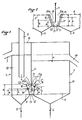
- first fluidization enclosure 1 adjoining and placed in communication with a second fluidization enclosure 2.
- second fluidization enclosure 2 each have a grid 3, 4 respectively and their own fluidizing gas inlet 5, 6 respectively, which makes it possible to fluidize the contents of one and the other enclosure separately.
- the enclosure 1 has in its upper part an overflow evacuation tube 7 directed downwards, and an upper closure wall 8 which is traversed by a downward tube 9 through which the solid in particles to be fluidized arrives.
- the enclosure 2 is separated from the enclosure 1 by a wall 11 which has a lower communication opening 12, this opening 12 being formed at the base of the wall 11 between the latter and a horizontal lower wall 13.
- the enclosure 2 also has a weir 14, at an altitude such that there is a difference in height H between the solid level of the bed 10 of the enclosure 1 which is the highest and the solid level of the bed 15 of the enclosure 2.
- This difference in height H produces a motive force which circulates the solids from the enclosure 1 to the enclosure 2 through the opening 12, when the enclosures are pressurized equally.
- the driving force can result from a different pressurization in each enclosure; in this case, the difference in height between the solid levels of the two beds may be zero or even the opposite of that in the case in point.
- the circulation of solids may be due other factors than a difference in level or pressure between the two speakers.
- the enclosure 2 comprises a bundle of tubes, the device functioning as a heat exchanger for example, the density of the bed 15 will be overall lower than that of the bed 10 and, as a result, circulation is establish between the speakers 1 and 2 through the opening 12.
- the density of the bed 15 will be overall lower than that of the bed 10 and, as a result, circulation is establish between the speakers 1 and 2 through the opening 12.
- FR-A-2581173 There may also be a difference in density if the fluidization speed of enclosure 2 is greater, than that achieved in enclosure 1.
- the latter is bordered by deflector panels 16 , 17 erected from the horizontal bottom wall 13, and thus delimiting compartments 20 and 21 on either side of the opening 12 and the wall 11.
- the panels 16 and 17 spaced from one another at their base of a value determined as a function of the flow rates which it is desired to see circulating through the opening 12, diverge from one another at an angle which can be between 0 and 45 ° relative to the wall 11.
- the panel 17 can be parallel to the wall 11 (0 ° inclination) and the panel 16 inclined from 15 to 30 ° on this wall.
- the opening 12 is a rectangular opening of height a , the panels 16 and 17 having the same length as the length of the opening 12 but being of height A.
- This opening 12 does not necessarily extend over the entire length of the separation wall 11 between the two fluidized enclosures.
- the compartments 20 and 21 are limited at their ends by vertical panels perpendicular to the wall 11, connecting the ends of the panels 16 and 17 to the wall 11.
- an aeration gas injector 18,19 shown here diagrammatically in the form of a tubular ramp opening into the corresponding compartment by means of either a continuous lateral slot, or a series of holes.
- This tubular ramp is fixed to the corresponding deflector panel 16 or 17. It can be constituted by orifices made in the panel which itself acts as a ramp while being partially hollow.
- the injection ramp located in the compartment 20 is at an altitude b such that b is greater than the height a of the opening 12.
- the injection ramp 19 located in the downstream compartment 21 is at an altitude c between b and A.
- aeration gas for example air, an inert gas or steam
- aeration gas for example air, an inert gas or steam
- the speed of the aeration fluid coming from the ramp 19 will be equal to 6 times the minimum fluidization speed for the particles of the order of 200 ⁇ m.
- This speed will advantageously be increased if the finer particles are treated (up to 20 times for particles of the order of 80 ⁇ m).
- This speed will be better measured at the maximum section 21a of the compartment, that is to say, taking into account the inclination of the walls that at which the compartment opens into the chamber 2.
- the flow rate delivered by the ramp 18 will be adjusted as a function of the flow rate of the desired solid through the opening 12 while at most being equal to the value generating an aeration speed through the section 20 a equal to the speed through the section 21 a .
- FIG. 2 is partially shown an alternative embodiment of FIG. 1 in which the regulator is arranged below the level of the grids 3 and 4 of fluidization.
- the sections 20 a and 21 has compartments 20 and 21 are at the level of these grids.
- the advantage of this embodiment lies in the ease of bringing the ventilation air into the distribution ramps 18 and 19 here constituted by the double-walled panels 16 and 17. This facility is due to the fact that the deflector panels are at the level of the wind boxes.
- the minimum fluidization speed of the enclosure 1 is 4 cm per second.
- the experimental device used has two square section enclosures with a side length of 300 mm and a height of 1 m, communicating through the opening 12 of length equal to 120 mm and height a equal to 30 mm.
- the distance between the base of the deflector panels 16 and 17 is 56 mm, their height A is 155 mm and their length is 120 mm.
- the angle that each of these panels makes with the partition wall 1 is 15 °.
- the ramp 18 is a tube perforated with orifices 2 mm in diameter, the perforations being at the height b equal to 35 mm, ie 5 mm above the upper edge 12 a of the communication opening 12.
- the ramp 19 is perforated in the same way, the altitude c of the perforations being 45 mm.
- the fluidization speeds in chambers 1 and 2 are respectively twice and four times the minimum fluidization speed defined above.
- the air flow injected by the manifold 19 is constant and equal to 4.4 m3 / h (at atmospheric pressure).
- the dimension H separating the two weirs 7 and 14 is equal to 170 mm.
- One of the advantages of the device according to the invention lies in the reduced dimensions of the passage orifice and of the deflector panels forming the adjustment device relative to the volume of the speakers.
- Another advantage of the invention lies in the fact that there is transfer of the solids from one enclosure to the other without transfer of the gases. The gas atmospheres of the two chambers are therefore independent and do not mix.
- the invention applies in particular to external heat exchangers of circulating fluidized beds used for example in the combustion of solid fuels. It also applies to regenerative reactors with isolation compartments.
Landscapes
- Engineering & Computer Science (AREA)
- Chemical & Material Sciences (AREA)
- Thermal Sciences (AREA)
- Mechanical Engineering (AREA)
- General Engineering & Computer Science (AREA)
- Combustion & Propulsion (AREA)
- Organic Chemistry (AREA)
- Chemical Kinetics & Catalysis (AREA)
- Physics & Mathematics (AREA)
- Devices And Processes Conducted In The Presence Of Fluids And Solid Particles (AREA)
- Flow Control (AREA)
- Physical Or Chemical Processes And Apparatus (AREA)
- Cosmetics (AREA)
- Magnetic Resonance Imaging Apparatus (AREA)
- Separating Particles In Gases By Inertia (AREA)
- Fluidized-Bed Combustion And Resonant Combustion (AREA)
- Quick-Acting Or Multi-Walled Pipe Joints (AREA)
- Pipeline Systems (AREA)
- Cyclones (AREA)
- Heat Treatment Of Strip Materials And Filament Materials (AREA)
- Air Transport Of Granular Materials (AREA)
Claims (12)
Applications Claiming Priority (2)
| Application Number | Priority Date | Filing Date | Title |
|---|---|---|---|
| FR8902401A FR2643571A1 (fr) | 1989-02-24 | 1989-02-24 | Regulateur non mecanique du debit de solides etabli entre deux milieux fluidises |
| FR8902401 | 1989-02-24 |
Publications (2)
| Publication Number | Publication Date |
|---|---|
| EP0384827A1 EP0384827A1 (de) | 1990-08-29 |
| EP0384827B1 true EP0384827B1 (de) | 1991-12-04 |
Family
ID=9379083
Family Applications (1)
| Application Number | Title | Priority Date | Filing Date |
|---|---|---|---|
| EP90400459A Expired - Lifetime EP0384827B1 (de) | 1989-02-24 | 1990-02-20 | Nichtmechanischer Regulator für den Feststoffdurchfluss zwischen zwei Wirbelmedien |
Country Status (13)
| Country | Link |
|---|---|
| EP (1) | EP0384827B1 (de) |
| JP (1) | JPH02265819A (de) |
| CN (1) | CN1054201A (de) |
| AT (1) | ATE69974T1 (de) |
| AU (1) | AU5006590A (de) |
| CA (1) | CA2010831A1 (de) |
| DE (1) | DE69000005D1 (de) |
| DK (1) | DK0384827T3 (de) |
| ES (1) | ES2028488T3 (de) |
| FI (1) | FI900821A7 (de) |
| FR (1) | FR2643571A1 (de) |
| GR (1) | GR3003484T3 (de) |
| ZA (1) | ZA901400B (de) |
Families Citing this family (3)
| Publication number | Priority date | Publication date | Assignee | Title |
|---|---|---|---|---|
| FI93701C (fi) * | 1993-06-11 | 1995-05-26 | Ahlstroem Oy | Menetelmä ja laite kuumien kaasujen käsittelemiseksi |
| NO312712B1 (no) | 1999-12-15 | 2002-06-24 | Norsk Hydro As | En sorterende fluid bed granulator samt fremgangsmåte for fluid bed granulering |
| CN201279453Y (zh) * | 2008-10-24 | 2009-07-29 | 邸丹 | 流态化水平循环组合反应装置 |
Family Cites Families (3)
| Publication number | Priority date | Publication date | Assignee | Title |
|---|---|---|---|---|
| FR2581173B1 (fr) * | 1985-04-24 | 1989-03-31 | Charbonnages De France | Echangeur a lit fluidise pour transfert de chaleur |
| EP0304523B1 (de) * | 1987-08-28 | 1992-07-08 | Exxon Research And Engineering Company | Apparat und Verfahren zur Temperaturkontrolle bei der Katalysatorregeneration |
| DE3708799A1 (de) * | 1987-03-18 | 1988-09-29 | Steinmueller Gmbh L & C | Verfahren zum verbrennen von kohlenstoffhaltigem material in einer wirbelschichtfeuerung und vorrichtung zur durchfuehrung des verfahrens |
-
1989
- 1989-02-24 FR FR8902401A patent/FR2643571A1/fr not_active Withdrawn
-
1990
- 1990-02-19 FI FI900821A patent/FI900821A7/fi not_active IP Right Cessation
- 1990-02-20 EP EP90400459A patent/EP0384827B1/de not_active Expired - Lifetime
- 1990-02-20 AT AT90400459T patent/ATE69974T1/de active
- 1990-02-20 DK DK90400459.5T patent/DK0384827T3/da active
- 1990-02-20 ES ES199090400459T patent/ES2028488T3/es not_active Expired - Lifetime
- 1990-02-20 DE DE9090400459T patent/DE69000005D1/de not_active Expired - Fee Related
- 1990-02-22 CN CN90101017A patent/CN1054201A/zh active Pending
- 1990-02-23 JP JP2041349A patent/JPH02265819A/ja active Pending
- 1990-02-23 ZA ZA901400A patent/ZA901400B/xx unknown
- 1990-02-23 AU AU50065/90A patent/AU5006590A/en not_active Abandoned
- 1990-02-23 CA CA002010831A patent/CA2010831A1/fr not_active Abandoned
-
1991
- 1991-12-31 GR GR91402263T patent/GR3003484T3/el unknown
Also Published As
| Publication number | Publication date |
|---|---|
| AU5006590A (en) | 1990-08-30 |
| CN1054201A (zh) | 1991-09-04 |
| GR3003484T3 (en) | 1993-02-17 |
| DE69000005D1 (de) | 1992-01-16 |
| ZA901400B (en) | 1990-11-28 |
| FI900821A0 (fi) | 1990-02-19 |
| CA2010831A1 (fr) | 1990-08-24 |
| JPH02265819A (ja) | 1990-10-30 |
| FR2643571A1 (fr) | 1990-08-31 |
| EP0384827A1 (de) | 1990-08-29 |
| DK0384827T3 (da) | 1992-03-23 |
| ATE69974T1 (de) | 1991-12-15 |
| FI900821A7 (fi) | 1990-08-25 |
| ES2028488T3 (es) | 1992-07-01 |
Similar Documents
| Publication | Publication Date | Title |
|---|---|---|
| EP0095427B1 (de) | Verfahren zur Regulierung des Wärmewirkungsgrads eines Wärmetauschers und ein Wärmetauscher zur Durchführung des Verfahrens | |
| EP0199655B1 (de) | Fliessbettaustauscher für Wärmeübertragung | |
| CH622080A5 (de) | ||
| FR2484280A1 (fr) | Reacteur a lit fluidise et procede de combustion de materiaux contenant des substances incombustibles a l'aide de ce reacteur | |
| FR2486223A1 (fr) | Echangeur de chaleur a lit fluidise | |
| FR2550316A1 (fr) | Appareil d'incineration en ligne a recuperation | |
| EP0384827B1 (de) | Nichtmechanischer Regulator für den Feststoffdurchfluss zwischen zwei Wirbelmedien | |
| EP0060207B1 (de) | Verfahren und Vorrichtung zum Ausscheiden von Ionen aus einer klaren Lösung oder aus einer Feststoffe enthaltenden Suspension durch in Kontakt bringen mit einem Austauscher | |
| EP0119115B1 (de) | Wärmeerzeuger zur Aufheizung von Fluiden durch Wärmetausch mittels eines Wirbelbettes und das Verfahren hierzu | |
| EP0568448B1 (de) | Zirkulierender Wirbelschichtreaktor mit externen Wärmetauschern gespeist durch interne Rezirkulation | |
| EP0044529B1 (de) | Ablenkgitter für eine Fluidumströmung und seine Anwendung in einer Vorrichtung | |
| FR2575546A1 (fr) | Echangeur perfectionne et methode pour realiser le transfert thermique a partir de particules solides | |
| EP0184689A1 (de) | Vorrichtung zur Entgasung einer Flüssigkeit | |
| FR2635274A1 (fr) | Appareil a lit fluidise en circulation | |
| FR3079814A1 (fr) | Dispositif de lutte contre l’incendie comprenant un drone energetiquement autonome | |
| EP0406336A1 (de) | Verteilerplatte in einem wirbelbettreaktor, wirbelbettreaktor und verfahren zum inbetriebsetzen eines wirbelbettreaktors. | |
| CA1283287C (fr) | Installation a lit fluidise | |
| EP0009455B1 (de) | Vorrichtung zum Wärmeaustausch zwischen festen Teilchen und einem Gasstrom | |
| FR2630621A1 (fr) | Sechoir a grain | |
| EP0694331B1 (de) | Verfahren und Apparat zur Regelung der internen Zirkulation eines Wirbelbettreaktors und mit einem solchen Apparat versehener Reaktor | |
| EP0147275B1 (de) | Verbrennungsofen für Wirbelbettkessel | |
| FR2896709A1 (fr) | Separateur de solides en particulier pour installation de combustion | |
| FR2476273A1 (fr) | Foyer a lit fluidise avec chambres multiples et procede pour son utilisation | |
| EP0094307B1 (de) | Strahlmühlen | |
| LU86352A1 (fr) | Echangeur de chaleur gaz-gaz |
Legal Events
| Date | Code | Title | Description |
|---|---|---|---|
| PUAI | Public reference made under article 153(3) epc to a published international application that has entered the european phase |
Free format text: ORIGINAL CODE: 0009012 |
|
| AK | Designated contracting states |
Kind code of ref document: A1 Designated state(s): AT BE CH DE DK ES FR GB GR IT LI LU NL SE |
|
| 17P | Request for examination filed |
Effective date: 19900710 |
|
| 17Q | First examination report despatched |
Effective date: 19910402 |
|
| GRAA | (expected) grant |
Free format text: ORIGINAL CODE: 0009210 |
|
| AK | Designated contracting states |
Kind code of ref document: B1 Designated state(s): AT BE CH DE DK ES FR GB GR IT LI LU NL SE |
|
| PG25 | Lapsed in a contracting state [announced via postgrant information from national office to epo] |
Ref country code: SE Effective date: 19911204 Ref country code: NL Effective date: 19911204 Ref country code: AT Effective date: 19911204 |
|
| REF | Corresponds to: |
Ref document number: 69974 Country of ref document: AT Date of ref document: 19911215 Kind code of ref document: T |
|
| GBT | Gb: translation of ep patent filed (gb section 77(6)(a)/1977) | ||
| REF | Corresponds to: |
Ref document number: 69000005 Country of ref document: DE Date of ref document: 19920116 |
|
| ITF | It: translation for a ep patent filed | ||
| PGFP | Annual fee paid to national office [announced via postgrant information from national office to epo] |
Ref country code: GR Payment date: 19920130 Year of fee payment: 3 |
|
| PGFP | Annual fee paid to national office [announced via postgrant information from national office to epo] |
Ref country code: DK Payment date: 19920211 Year of fee payment: 3 |
|
| PGFP | Annual fee paid to national office [announced via postgrant information from national office to epo] |
Ref country code: ES Payment date: 19920213 Year of fee payment: 3 |
|
| PGFP | Annual fee paid to national office [announced via postgrant information from national office to epo] |
Ref country code: DE Payment date: 19920217 Year of fee payment: 3 |
|
| PGFP | Annual fee paid to national office [announced via postgrant information from national office to epo] |
Ref country code: BE Payment date: 19920227 Year of fee payment: 3 |
|
| PG25 | Lapsed in a contracting state [announced via postgrant information from national office to epo] |
Ref country code: LU Free format text: LAPSE BECAUSE OF NON-PAYMENT OF DUE FEES Effective date: 19920229 Ref country code: LI Effective date: 19920229 Ref country code: CH Effective date: 19920229 |
|
| REG | Reference to a national code |
Ref country code: DK Ref legal event code: T3 |
|
| NLV1 | Nl: lapsed or annulled due to failure to fulfill the requirements of art. 29p and 29m of the patents act | ||
| REG | Reference to a national code |
Ref country code: ES Ref legal event code: FG2A Ref document number: 2028488 Country of ref document: ES Kind code of ref document: T3 |
|
| PLBE | No opposition filed within time limit |
Free format text: ORIGINAL CODE: 0009261 |
|
| STAA | Information on the status of an ep patent application or granted ep patent |
Free format text: STATUS: NO OPPOSITION FILED WITHIN TIME LIMIT |
|
| REG | Reference to a national code |
Ref country code: CH Ref legal event code: PL Ref country code: GR Ref legal event code: FG4A Free format text: 3003484 |
|
| 26N | No opposition filed | ||
| PG25 | Lapsed in a contracting state [announced via postgrant information from national office to epo] |
Ref country code: DK Effective date: 19930220 |
|
| REG | Reference to a national code |
Ref country code: DK Ref legal event code: EBP |
|
| PG25 | Lapsed in a contracting state [announced via postgrant information from national office to epo] |
Ref country code: ES Free format text: LAPSE BECAUSE OF NON-PAYMENT OF DUE FEES Effective date: 19930222 |
|
| PG25 | Lapsed in a contracting state [announced via postgrant information from national office to epo] |
Ref country code: BE Effective date: 19930228 |
|
| BERE | Be: lapsed |
Owner name: CHARBONNAGES DE FRANCE Effective date: 19930228 |
|
| PG25 | Lapsed in a contracting state [announced via postgrant information from national office to epo] |
Ref country code: GR Free format text: THE PATENT HAS BEEN ANNULLED BY A DECISION OF A NATIONAL AUTHORITY Effective date: 19930831 |
|
| PG25 | Lapsed in a contracting state [announced via postgrant information from national office to epo] |
Ref country code: DE Effective date: 19931103 |
|
| PG25 | Lapsed in a contracting state [announced via postgrant information from national office to epo] |
Ref country code: GB Effective date: 19940220 |
|
| GBPC | Gb: european patent ceased through non-payment of renewal fee |
Effective date: 19940220 |
|
| REG | Reference to a national code |
Ref country code: GR Ref legal event code: MM2A Free format text: 3003484 |
|
| PGFP | Annual fee paid to national office [announced via postgrant information from national office to epo] |
Ref country code: FR Payment date: 19960130 Year of fee payment: 7 |
|
| PG25 | Lapsed in a contracting state [announced via postgrant information from national office to epo] |
Ref country code: FR Effective date: 19971030 |
|
| REG | Reference to a national code |
Ref country code: FR Ref legal event code: ST |
|
| REG | Reference to a national code |
Ref country code: ES Ref legal event code: FD2A Effective date: 19990503 |
|
| PG25 | Lapsed in a contracting state [announced via postgrant information from national office to epo] |
Ref country code: IT Free format text: LAPSE BECAUSE OF NON-PAYMENT OF DUE FEES;WARNING: LAPSES OF ITALIAN PATENTS WITH EFFECTIVE DATE BEFORE 2007 MAY HAVE OCCURRED AT ANY TIME BEFORE 2007. THE CORRECT EFFECTIVE DATE MAY BE DIFFERENT FROM THE ONE RECORDED. Effective date: 20050220 |