EP0384882A2 - Réglage du taux d'injection des injecteurs de combustible du type à accumulateur - Google Patents
Réglage du taux d'injection des injecteurs de combustible du type à accumulateur Download PDFInfo
- Publication number
- EP0384882A2 EP0384882A2 EP90630054A EP90630054A EP0384882A2 EP 0384882 A2 EP0384882 A2 EP 0384882A2 EP 90630054 A EP90630054 A EP 90630054A EP 90630054 A EP90630054 A EP 90630054A EP 0384882 A2 EP0384882 A2 EP 0384882A2
- Authority
- EP
- European Patent Office
- Prior art keywords
- valve
- chamber
- amplifier
- pressure
- accumulator
- Prior art date
- Legal status (The legal status is an assumption and is not a legal conclusion. Google has not performed a legal analysis and makes no representation as to the accuracy of the status listed.)
- Withdrawn
Links
Images


Classifications
-
- F—MECHANICAL ENGINEERING; LIGHTING; HEATING; WEAPONS; BLASTING
- F02—COMBUSTION ENGINES; HOT-GAS OR COMBUSTION-PRODUCT ENGINE PLANTS
- F02M—SUPPLYING COMBUSTION ENGINES IN GENERAL WITH COMBUSTIBLE MIXTURES OR CONSTITUENTS THEREOF
- F02M57/00—Fuel-injectors combined or associated with other devices
- F02M57/02—Injectors structurally combined with fuel-injection pumps
- F02M57/022—Injectors structurally combined with fuel-injection pumps characterised by the pump drive
- F02M57/025—Injectors structurally combined with fuel-injection pumps characterised by the pump drive hydraulic, e.g. with pressure amplification
- F02M57/026—Construction details of pressure amplifiers, e.g. fuel passages or check valves arranged in the intensifier piston or head, particular diameter relationships, stop members, arrangement of ports or conduits
-
- F—MECHANICAL ENGINEERING; LIGHTING; HEATING; WEAPONS; BLASTING
- F02—COMBUSTION ENGINES; HOT-GAS OR COMBUSTION-PRODUCT ENGINE PLANTS
- F02M—SUPPLYING COMBUSTION ENGINES IN GENERAL WITH COMBUSTIBLE MIXTURES OR CONSTITUENTS THEREOF
- F02M45/00—Fuel-injection apparatus characterised by having a cyclic delivery of specific time/pressure or time/quantity relationship
-
- F—MECHANICAL ENGINEERING; LIGHTING; HEATING; WEAPONS; BLASTING
- F02—COMBUSTION ENGINES; HOT-GAS OR COMBUSTION-PRODUCT ENGINE PLANTS
- F02M—SUPPLYING COMBUSTION ENGINES IN GENERAL WITH COMBUSTIBLE MIXTURES OR CONSTITUENTS THEREOF
- F02M47/00—Fuel-injection apparatus operated cyclically with fuel-injection valves actuated by fluid pressure
- F02M47/02—Fuel-injection apparatus operated cyclically with fuel-injection valves actuated by fluid pressure of accumulator-injector type, i.e. having fuel pressure of accumulator tending to open, and fuel pressure in other chamber tending to close, injection valves and having means for periodically releasing that closing pressure
-
- F—MECHANICAL ENGINEERING; LIGHTING; HEATING; WEAPONS; BLASTING
- F02—COMBUSTION ENGINES; HOT-GAS OR COMBUSTION-PRODUCT ENGINE PLANTS
- F02M—SUPPLYING COMBUSTION ENGINES IN GENERAL WITH COMBUSTIBLE MIXTURES OR CONSTITUENTS THEREOF
- F02M57/00—Fuel-injectors combined or associated with other devices
- F02M57/02—Injectors structurally combined with fuel-injection pumps
- F02M57/022—Injectors structurally combined with fuel-injection pumps characterised by the pump drive
- F02M57/025—Injectors structurally combined with fuel-injection pumps characterised by the pump drive hydraulic, e.g. with pressure amplification
-
- F—MECHANICAL ENGINEERING; LIGHTING; HEATING; WEAPONS; BLASTING
- F02—COMBUSTION ENGINES; HOT-GAS OR COMBUSTION-PRODUCT ENGINE PLANTS
- F02M—SUPPLYING COMBUSTION ENGINES IN GENERAL WITH COMBUSTIBLE MIXTURES OR CONSTITUENTS THEREOF
- F02M59/00—Pumps specially adapted for fuel-injection and not provided for in groups F02M39/00 -F02M57/00, e.g. rotary cylinder-block type of pumps
- F02M59/02—Pumps specially adapted for fuel-injection and not provided for in groups F02M39/00 -F02M57/00, e.g. rotary cylinder-block type of pumps of reciprocating-piston or reciprocating-cylinder type
- F02M59/10—Pumps specially adapted for fuel-injection and not provided for in groups F02M39/00 -F02M57/00, e.g. rotary cylinder-block type of pumps of reciprocating-piston or reciprocating-cylinder type characterised by the piston-drive
- F02M59/105—Pumps specially adapted for fuel-injection and not provided for in groups F02M39/00 -F02M57/00, e.g. rotary cylinder-block type of pumps of reciprocating-piston or reciprocating-cylinder type characterised by the piston-drive hydraulic drive
-
- F—MECHANICAL ENGINEERING; LIGHTING; HEATING; WEAPONS; BLASTING
- F02—COMBUSTION ENGINES; HOT-GAS OR COMBUSTION-PRODUCT ENGINE PLANTS
- F02M—SUPPLYING COMBUSTION ENGINES IN GENERAL WITH COMBUSTIBLE MIXTURES OR CONSTITUENTS THEREOF
- F02M59/00—Pumps specially adapted for fuel-injection and not provided for in groups F02M39/00 -F02M57/00, e.g. rotary cylinder-block type of pumps
- F02M59/44—Details, components parts, or accessories not provided for in, or of interest apart from, the apparatus of groups F02M59/02 - F02M59/42; Pumps having transducers, e.g. to measure displacement of pump rack or piston
- F02M59/46—Valves
- F02M59/466—Electrically operated valves, e.g. using electromagnetic or piezoelectric operating means
Definitions
- the present invention relates generally to fuel injection equipment for internal combustion engines and relates more particularly to apparatus for controlling the rate of injection in accumulator type injectors.
- accumulator type fuel injection system fuel is accumulated under high pressure in the injection nozzles and means are provided for holding the valve needle closed against the pressurized fluid until the proper time to initiate injection.
- the additional nozzle closing force which supplements the valve spring force is in the form of a high fuel pressure acting against the upper end of the valve, the release of which permits the valve to open under the influence of the accumulated fuel pressure.
- a shortcoming of accumulator type injectors is their characteristic high initial injection rate which drops continuously through the injection interval. This is an undesirable rate characteristic since in most cases, it is desirable to initiate injection at a substantially lower than maximum rate, in some cases even using a pilot injection, to optimize the combustion process.
- the present invention is particularly adapted for use with the type of accumulator injector which employs an amplifier piston to hydraulically raise the pressure of the fuel delivered to the accumulator chamber by the rail pump to a high level which might be ten to twenty times the pressure delivered by the pump.
- An example of such an injection system is shown in U.S. Patent 4,628,881, issued on December 16, 1986.
- a fuel supply rail pressure on the order of 1,000 psi is supplied continuously to unit injectors which through appropriate passage and valve means assure a continuous accumulator chamber pressure substantially equal to the rail pressure and well below the pressure required to open the nozzle valve against the closing spring.
- a double acting solenoid valve when actuated admits rail pressure to the upper end of a pressure amplifying piston assembly which acts to increase the fuel pressure in the accumulator chamber, for example, by a factor of 15.
- a check valve member disposed concentrically around the upper end of the injection valve needle permits the boosting of the pressure in the accumulator chamber but prevents any backflow when the amplified pressure is released.
- the upper end of the valve needle extends through the check valve element and is subjected to the amplified pressure, thus supplementing the valve needle closing spring and holding the valve needle closed until the amplified pressure is released.
- the double acting valve closes the rod piston inlet to the amplified piston and opens the piston to drain, resulting in a rapid decompression of the fuel pressure above the check valve, thus allowing the valve needle to move sharply upwardly under the force of the accumulated fuel charge.
- the nozzle closes under the spring force. This cycle is repeated for each firing sequence of the engine cylinder.
- a invention comprises a modification of the duct connecting the amplifier piston with the drain port to provide an initial piston movement sufficient to allow the valve needle to open, and then move at a controlled rate thereby varying the needle orifice and effectively controlling injection rate.
- the modification of the amplifier piston outlet duct comprises a conduit within the piston itself which is sequentially aligned with a plurality of passages in the piston chamber wall to vary the rate at which the piston moves.
- a snubber valve is provided in the amplifier piston spill duct, the seating of which produces a partial nozzle valve lift and a low initial injection rate. The subsequent spill through the snubber orifice permits full nozzle valve lift and an unrestricted injection rate.
- the invention additionally comprises in a further embodiment the modification of the solenoid controlled spill valve which, instead of being fully opened or fully closed is, in the open position, provided with a flow restriction which will limit the spill flow rate and accordingly produce an improved injection rate characteristic.
- Additional embodiments of the invention employ means for directly delaying the full opening of the valve needle after an initial valve opening. In one embodiment, this is accomplished by use of a restriction between the accumulated flow chamber and the valve seat. Upon initial valve lift, the volume below the restriction discharges followed by a pause and pressure delay. Leakage past the restriction rebuilds the pressure beneath the valve and lifts the valve needle to clear the restriction.
- valve needle is divided and the upper portion provided with a bleed orifice.
- an hydraulic gap exists between the upper and lower valve portions.
- the amplifier pressure is released, the upper valve portion moves quickly against its stop, permitting the lower valve to open partly providing a pilot injection.
- Fuel is forced from the hydraulic gap through the bleed orifice to slow the injection rate during the initial portion of the injection interval.
- Another object of the invention is to provide apparatus for controlling injection rate as described, the embodiments of which are of a relatively simple construction and which can be readily employed with a known type of injector with minimal modifications thereto.
- the present invention is an improvement on a conventional form of accumulator injector and particularly that disclosed in U.S. Patent 4,628,881, which is hereby incorporated by reference. Since the present invention involves structural modifications of the unit injector of the injection system disclosed in the patent, only the unit injector disclosed in that patent is shown and described in the present application. Reference may be had to the patent should further details regarding the overall system or its operating characteristics be desired.
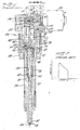
- Fig. 1 of the present application shows an accumulator type unit injector known in the art and is essentially the injector shown in Figs. 5a and 5b of the above patent.
- the present description will be somewhat general with detail included only as necessary to provide a complete understanding of the present improvements.
- a unit injector 20 in accordance with the injector includes an injector body assembly 22 comprised of a number of elements which are threadedly secured together in a conventional manner.
- the lower end of the injector comprises an injector nozzle 24 having a tip 26 which upon mounting of the injector on an engine extends into an engine combustion chamber for delivery of a fine spray of fuel through a plurality of spray orifices 28.
- the valve includes a needle valve 30 which at its lower end engages a valve seat 32 to close the fuel passage from the nozzle bore 34 to the orifices 26.
- the valve 30 is biased downwardly against the seat 32 by a spring 36 disposed in spring chamber 38 and seated at its upper end against a spring seat 40 on the body assembly and at its lower end against a washer 42 supported on shoulder 44 of the valve.
- a chamber 46 above the spring chamber 38 contains a sleeve-like check valve 48 which is biased upwardly by the compression coil spring 50 seated on the body assembly.
- the check valve 48 includes a central bore 52 which closely fits around the upper end of the needle valve 30 in sliding relation therewith. The outer annular upper edge of the check valve 48 engages the lower surface 54 of the valve body in the upper limit position of the valve to seal the chamber 46, spring chamber 38 and bore 34, which together comprise the accumulator chamber, from the upper portion of the injector.
- a conduit 58 in the valve body communicating with the bore 56 permits fuel flow through check valve 60 and passage 62 into an amplifier chamber 64 which comprises the lower part of a bore 66 in the valve body within which is slideably disposed rod 68 of amplifier piston 70 slideably disposed in a larger bore 72.
- the upper end 74 of the needle valve 30 is continuously exposed to the fluid pressure in the amplifier chamber 64 by means of a small bore 76 in a washer 78 flush with the injector body surface 54.
- the washer 78 serves as an upper limit stop for the valve 30.
- a duct 80 connects the upper end of the amplifier piston bore 72 with a solenoid controlled valve assembly 82 which selectively connects the amplifier piston with either the rail pressure fuel entering through port 56 or a drain port 84 returning the fuel to the low fuel tank pressure which is essentially atmospheric.
- the valve assembly 82 includes a solenoid 86, the core of which includes a rod 88 extending into engagement with a ball 90 cooperatively arranged with respect to a valve seat 92 which when opened as shown in Fig. 1 permits a fuel flow from the amplifier piston cyclinder through duct 80 and out through the drain port 84.
- Actuation of the solenoid 86 shifts the valve assembly 82 to permit the rail pressure to enter through duct 80 into the amplifier piston chamber, thereby driving the piston rod 68 downwardly and compressing the fuel in the amplifier chamber 64 as well as the accumulator chamber to a high pressure, for example on the order of 15,000-20,000 psi.
- the fuel charge in the accumulator chamber is then at its injection pressure and ready for injection, but the valve needle 30 will not open since the force of the spring 36 is augmented by the pressure in the amplifier chamber 64 acting against the upper end 74 of the valve.
- the solenoid valve 86 is deactivated, permitting the valve assembly 82 to shift to the right under the influence of the pressure in the inlet port bearing on valve ball 94.
- the valve needle then opens quickly under the influence of the high pressure fuel in the accumulator chamber, the check valve 48 being held closed under the influence of the spring 50 and the differential pressure bearing thereagainst. The fuel then passes from the nozzle bore 34 out through the spray passages 28 into the engine combustion chamber.
- Fig. 2 the rate of fuel injection is shown versus time and it may be seen that it is characteristic of an accumulator type injector to produce an initial maximum rate of flow which drops off rather sharply until the pressure drops below the spring generated nozzle closing pressure, at which point the nozzle closes and injection ends. It is the primary object of the present invention to shape this rate curve in a manner more conducive to efficient combustion since it is generally desirably to initiate injection at a rate well below the maximum injection rate both for the purposes of providing complete combustion and minimizing the generation of pollutants.
- the following embodiments of the invention are each carried out by a relatively minor modification of the prior art injector structure described above and it will be seen that a variety of rate curves can be achieved utilizing the modifications of the invention.
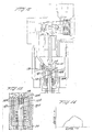
- FIG. 3 is substantially identical to the upper portion of the injector shown in Fig. 1 but showing a modification of the amplifier piston and the duct connecting the amplifier piston with the valve 82.
- the duct 80′ extends from the valve assembly 82 along side of and spaced from the amplifier cylinder 72 and communicates with the cylinder by means of a smaller lower port 106 and a larger upper port 108.
- the amplifier piston 70′ is modified to include a transverse passage 110 which communicates with an annulus 112 in the side wall thereof.
- the passage 110 intersects a central longitudinal passage 114 which opens into the closed upper end chamber 116 of the cylinder 72.
- the amplifier piston 70′ is shown in its lowermost position just after the opening of the valve assembly 82 to drain fuel from the amplifier valve assembly.
- the annulus 112 is partly opened to the duct port 106 and pressure relief takes place at a slow initial rate due to the small size of the port 106.
- the pressure in the amplifier chamber 64 and hence in the accumulator chamber is relieved at a rate slower than that of the injector of Fig. 1, hence changing the rate of opening of the valve needle and the rate of fuel injection.
- the initial fuel flow from the amplifier chamber 116 through the passages 114, 110 and annulus 112 into the small duct 106 produces a small pilot injection and as the annulus passes between the ports 106 and 108, a diminution in the rate of fuel delivery as shown diagrammatically in Fig. 5.
- the full fuel delivery rate is achieved when the annulus 112 moves opposite the port 108, which position is shown in Fig. 3.
- the embodiment of Figs. 3 and 4 functions essentially by control of the decay of pressure in the amplifier chamber 64 and a consequent control of the rate of opening of the needle valve 30 in view of the exposure of the end 74 of the valve needle to the amplifier chamber pressure.
- This decay is governed by the rate of dumping of the fuel from the amplifier chamber 116 by varying the spill flow area to the drain duct.
- the desired injection rate can be controlled as desired, and the rate curve of Fig. 5 is simply an example of the type of rate control that can be achieved by this embodiment.
- a second embodiment of the invention as shown in Figs. 6 and 7 utilizes this same general concept to control injection rate.
- the injector as shown in Fig. 1 is modified to incorporate a snubber valve within the amplifier duct.
- the amplifier duct 80 ⁇ extends from the upper end of the amplifier cylinder 72 directly into the valve assembly 82.
- the duct 80 ⁇ is enlarged to provide a cylindrical snubber valve chamber 118 within which the snubber valve 120 is disposed.
- the valve 120 comprises a disk of slightly smaller diameter than the chamber 118 with a bleed passage 121 therein and having an axial dimension somewhat less than the chamber 118 so that it may move from a lower position as shown in Fig. 6, wherein it rests against an annular spring 122, to an upper position shown in Fig. 7 wherein it engages a shoulder 124.
- a compression coil spring 126 biases the snubber valve toward the lower limit position shown in Fig. 6.
- Fig. 6 the injector is shown following the injection cycle and prior to the recharging and amplifying of the charge.
- the solenoid valve 82 Upon actuation of the solenoid valve 82, the flow from the inlet duct 56 through the valve assembly 82 through duct 80 ⁇ takes place through the bleed passage 121 in the snubber valve 120.
- amplification of the fuel charge in the accumulator chamber will take place somewhat more slowly than usual, this is unimportant since a relatively large amount of time is available for this function.
- valve assembly 82 is modified to a minor degree by providing a restriction in the drain valve comprising the ball 90 and seat 92.
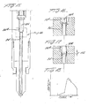
- the ball 90′ of the modified valve assembly 82′ includes a stem 92a which is disposed within the bore of the valve seat 92 and which includes a plurality of spaced flutes 90b thereon which slidingly guide the stem portion within the valve seat bore.
- the flutes serve both to align the ball 90′ as well as to provide a predetermined degree of restriction to the valve seat and accordingly a controlled rate of decay of pressure in the accumulator chamber 64 and a consequently regulated rise of the valve needle 30.
- the rate curve using this embodiment may be such as to provide a relatively constant rate of injection over the course of the injection interval in contrast to the rapidly dropping rate characteristic of the prior art.
- the ball 90′ in the closed position seats in the valve seat 92 in the usual fashion.
- the valve stem 90a and the flutes 90b are sized to provide a sufficient restriction in the valve seat so as to limit the flow rate of fuel from the amplifier cylinder duct 80 to the drain port 84.
- the advantage of this embodiment is its simplicity and economy in that only a minor element of the injector valve need be modified, and this modification is extremely simple and inexpensive.
- a fourth embodiment of the invention is shown in Figs. 12 and 13 and differs from the previously described three embodiments in the sense that the amplifier piston is allowed to open rapidly, thus permitting the pressure in the amplifier chamber 64 to quickly decay.
- the opening of the nozzle valve is controlled in this embodiment by modifying the exposure of the upper end of the needle valve to the accumulator chamber.
- valve needle is divided into a lower valve 30a and an upper valve 30b, the upper valve 30b being relatively short in relation to the lower valve 30a.
- the upper valve 30b includes an annular flange 30c extending radially outwardly around its upper end, which flange seats on the check valve 48 in the lowered position of the valve members as shown in Fig. 12.
- a central bleed passage 30d extends axially through the upper valve 30b.
- the upper and lower valve elements are in the position shown in Fig. 12, although the upper valve element will move with the movement of the check valve 48 during charging and amplification of the charge in the accumulator chamber.
- the lower valve element 30a and upper valve element 30b will rapidly move upwardly separated by the hydraulic gap 130 to permit the lower valve element 30a to lift off its seat and initiate injection.
- the upper valve element engages the washer 78 the lower valve 30a will rise at a more gradual rate since the fuel in the hydraulic gap 130 must pass through the bleed passage 30d to permit the complete opening of the valve.
- Fig. 12 the upper valve element will move with the movement of the check valve 48 during charging and amplification of the charge in the accumulator chamber.
- the lower valve element 30a and upper valve element 30b will rapidly move upwardly separated by the hydraulic gap 130 to permit the lower valve element 30a to lift off its seat and initiate injection.
- the lower valve 30a will rise at a more gradual rate since the fuel in the hydraulic gap 130 must pass through the bleed passage 30d to permit the complete
- the maximum injection rate can be delayed utilizing this embodiment until approximately the midpoint of the injection interval.
- the operation of this embodiment is not dissimilar from that of Figs. 6 and 7 in the sense that the upper valve 30b acts much like the snubber valve of the previously described embodiment.
- a fifth embodiment of the invention is shown in Figs. 15-17 and is similar to the preceding embodiment in the sense that it involves a modification of the needle valve 30 with a resultant control of the rate of opening of the valve.
- a close fit between the valve and the nozzle body at some distance of the valve needle from the valve seat effectively divides the accumulator chamber into two portions.
- the volume below the restriction discharges through the spray passages, followed by a slow rebuilding of the pressure until the valve lifts to clear the restriction. The remainder of the accumulated charge then is injected at a normal declining rate.
- an enlarged diameter upper portion 30a of the needle valve 30 is disposed primarily in an enlarged bore portion 34a but extends downwardly a short distance 132 into the normal size bore 34′ in a close fitting relationship therewith.
- the clearance at this overlapped portion provides a restriction but is sufficient to allow a bleed flow of fuel between the overlapped valve portion 30a and the valve bore 34′.
- the amplified fuel pressure Prior to injection, the amplified fuel pressure is the same above and below the restriction and hence the valve will open promptly upon relief of pressure in the amplifier chamber 64.
- the flow through the restriction between the enlarged needle valve portion 30a and the bore 34′ will result in a slow increase in flow rate until the restriction is cleared when the portion 30a is entirely within the enlarged bore 34a shown in Fig. 16.
Landscapes
- Engineering & Computer Science (AREA)
- Chemical & Material Sciences (AREA)
- Combustion & Propulsion (AREA)
- Mechanical Engineering (AREA)
- General Engineering & Computer Science (AREA)
- Physics & Mathematics (AREA)
- Electromagnetism (AREA)
- Fluid Mechanics (AREA)
- Fuel-Injection Apparatus (AREA)
Applications Claiming Priority (2)
| Application Number | Priority Date | Filing Date | Title |
|---|---|---|---|
| US07/316,255 US4948049A (en) | 1989-02-24 | 1989-02-24 | Rate control in accumulator type fuel injectors |
| US316255 | 1989-02-24 |
Publications (2)
| Publication Number | Publication Date |
|---|---|
| EP0384882A2 true EP0384882A2 (fr) | 1990-08-29 |
| EP0384882A3 EP0384882A3 (fr) | 1991-04-03 |
Family
ID=23228258
Family Applications (1)
| Application Number | Title | Priority Date | Filing Date |
|---|---|---|---|
| EP19900630054 Withdrawn EP0384882A3 (fr) | 1989-02-24 | 1990-02-23 | Réglage du taux d'injection des injecteurs de combustible du type à accumulateur |
Country Status (2)
| Country | Link |
|---|---|
| US (1) | US4948049A (fr) |
| EP (1) | EP0384882A3 (fr) |
Cited By (1)
| Publication number | Priority date | Publication date | Assignee | Title |
|---|---|---|---|---|
| WO2000039447A1 (fr) * | 1998-12-23 | 2000-07-06 | Siemens Aktiengesellschaft | Etranglement pour systemes d'injection diesel |
Families Citing this family (21)
| Publication number | Priority date | Publication date | Assignee | Title |
|---|---|---|---|---|
| DE3844489A1 (de) * | 1988-12-31 | 1990-07-05 | Bosch Gmbh Robert | Kraftstoffeinspritzvorrichtung |
| US5148987A (en) * | 1990-07-05 | 1992-09-22 | Yamaha Hatsudoki Kabushiki Kaisha | High pressure fuel injection device for engine |
| IT220661Z2 (it) * | 1990-10-31 | 1993-10-08 | Elasis Sistema Ricerca Fita Nel Mezzogiorno Soc.Consortile P.A. | Perfezionamenti al sistema di tenuta ad alta pressione della valvola pilota di un iniettore elettromagnetico per sistemi di iniezione del combustibile di motori a combustione interna |
| EP0601038B1 (fr) * | 1991-08-26 | 1997-03-05 | Interlocking Buildings Pty. Ltd. | Appareil d'injection |
| EP0614507B1 (fr) * | 1991-11-29 | 1996-09-25 | Caterpillar Inc. | Ralentisseur hydraulique de la vitesse de fermeture d'une soupape de moteur sur un siege de soupape |
| US5421359A (en) * | 1992-01-13 | 1995-06-06 | Caterpillar Inc. | Engine valve seating velocity hydraulic snubber |
| US5323964A (en) * | 1992-03-31 | 1994-06-28 | Cummins Engine Company, Inc. | High pressure unit fuel injector having variable effective spill area |
| DE4302668A1 (de) * | 1993-01-30 | 1994-08-04 | Bosch Gmbh Robert | Kraftstoffeinspritzeinrichtung für Brennkraftmaschinen |
| DE4341546A1 (de) * | 1993-12-07 | 1995-06-08 | Bosch Gmbh Robert | Kraftstoffeinspritzeinrichtung für Brennkraftmaschinen |
| US5641121A (en) * | 1995-06-21 | 1997-06-24 | Servojet Products International | Conversion of non-accumulator-type hydraulic electronic unit injector to accumulator-type hydraulic electronic unit injector |
| US5740782A (en) * | 1996-05-20 | 1998-04-21 | Lowi, Jr.; Alvin | Positive-displacement-metering, electro-hydraulic fuel injection system |
| JP3704957B2 (ja) * | 1998-07-06 | 2005-10-12 | いすゞ自動車株式会社 | インジェクタ |
| US6109542A (en) * | 1998-09-21 | 2000-08-29 | Cummins Engine Company, Inc. | Servo-controlled fuel injector with leakage limiting device |
| US6270024B1 (en) | 2000-01-12 | 2001-08-07 | Woodward Governor Company | Hydraulically actuated fuel injector cartridge and system for high pressure gaseous fuel injection |
| US6595188B2 (en) * | 2001-12-04 | 2003-07-22 | Caterpillar Inc | Compact valve assembly and fuel injector using same |
| DE10251679A1 (de) * | 2002-11-07 | 2004-05-19 | Robert Bosch Gmbh | Druckverstärker mit hubabhängiger Bedämpfung |
| US9291134B2 (en) * | 2013-03-11 | 2016-03-22 | Stanadyne Llc | Anti-cavitation throttle for injector control valve |
| US9228550B2 (en) * | 2013-03-11 | 2016-01-05 | Stanadyne Llc | Common rail injector with regulated pressure chamber |
| US10895233B2 (en) | 2019-05-16 | 2021-01-19 | Caterpillar Inc. | Fuel system having fixed geometry flow regulating valve for limiting injector cross talk |
| US11220980B2 (en) | 2019-05-16 | 2022-01-11 | Caterpillar Inc. | Fuel system having isolation valves between fuel injectors and common drain conduit |
| US11280306B1 (en) | 2021-01-15 | 2022-03-22 | Caterpillar Inc. | Fuel injector having dry-running protection valve and fuel system using same |
Family Cites Families (6)
| Publication number | Priority date | Publication date | Assignee | Title |
|---|---|---|---|---|
| DE2213776A1 (de) * | 1972-03-22 | 1973-09-27 | Bosch Gmbh Robert | Kraftstoffeinspritzanlage fuer brennkraftmaschinen |
| US4046112A (en) * | 1975-10-20 | 1977-09-06 | General Motors Corporation | Electromagnetic fuel injector |
| US4129256A (en) * | 1977-09-12 | 1978-12-12 | General Motors Corporation | Electromagnetic unit fuel injector |
| US4628881A (en) * | 1982-09-16 | 1986-12-16 | Bkm, Inc. | Pressure-controlled fuel injection for internal combustion engines |
| US4605166A (en) * | 1985-02-21 | 1986-08-12 | Stanadyne, Inc. | Accumulator injector |
| GB8618839D0 (en) * | 1986-08-01 | 1986-09-10 | Lucas Ind Plc | Valve assembly |
-
1989
- 1989-02-24 US US07/316,255 patent/US4948049A/en not_active Expired - Fee Related
-
1990
- 1990-02-23 EP EP19900630054 patent/EP0384882A3/fr not_active Withdrawn
Cited By (1)
| Publication number | Priority date | Publication date | Assignee | Title |
|---|---|---|---|---|
| WO2000039447A1 (fr) * | 1998-12-23 | 2000-07-06 | Siemens Aktiengesellschaft | Etranglement pour systemes d'injection diesel |
Also Published As
| Publication number | Publication date |
|---|---|
| EP0384882A3 (fr) | 1991-04-03 |
| US4948049A (en) | 1990-08-14 |
Similar Documents
| Publication | Publication Date | Title |
|---|---|---|
| US4948049A (en) | Rate control in accumulator type fuel injectors | |
| US4605166A (en) | Accumulator injector | |
| US5143291A (en) | Two-stage hydraulic electrically-controlled unit injector | |
| US5505384A (en) | Rate shaping control valve for fuel injection nozzle | |
| US5551391A (en) | Accumulator fuel injection system | |
| US5423484A (en) | Injection rate shaping control ported barrel for a fuel injection system | |
| US4171099A (en) | Fuel injection nozzle for internal combustion engines | |
| JPH07189851A (ja) | 内燃機関用の燃料噴射装置 | |
| US6053421A (en) | Hydraulically-actuated fuel injector with rate shaping spool control valve | |
| GB2086473A (en) | Fuel injection valve for compression ignition engines | |
| US4173208A (en) | Fuel systems for an internal combustion engine | |
| US6026785A (en) | Hydraulically-actuated fuel injector with hydraulically assisted closure of needle valve | |
| JP2002531769A (ja) | 着座ピンアクチュエータを備える油圧作動燃料噴射器 | |
| US4317541A (en) | Fuel injector-pump unit with hydraulic needle fuel injector | |
| US6161773A (en) | Fuel injector nozzle with guide to check clearance passage providing injection rate shaping | |
| US6119962A (en) | Fuel injector having a trapped volume nozzle assembly with a pressure relief valve | |
| GB2340542A (en) | Direct control fuel injector with a dual flow rate orifice | |
| JPH0525032B2 (fr) | ||
| US6928986B2 (en) | Fuel injector with piezoelectric actuator and method of use | |
| US5934570A (en) | Injector | |
| US20040089269A1 (en) | Fuel injection device with a pressure booster | |
| US6595188B2 (en) | Compact valve assembly and fuel injector using same | |
| US6257203B1 (en) | Injector with variable needle valve opening pressure | |
| US4081140A (en) | Capsule-type fuel nozzle | |
| US5390856A (en) | Fuel injectors for diesel engines |
Legal Events
| Date | Code | Title | Description |
|---|---|---|---|
| PUAI | Public reference made under article 153(3) epc to a published international application that has entered the european phase |
Free format text: ORIGINAL CODE: 0009012 |
|
| AK | Designated contracting states |
Kind code of ref document: A2 Designated state(s): DE ES FR GB IT LU NL SE |
|
| PUAL | Search report despatched |
Free format text: ORIGINAL CODE: 0009013 |
|
| AK | Designated contracting states |
Kind code of ref document: A3 Designated state(s): DE ES FR GB IT LU NL SE |
|
| 17P | Request for examination filed |
Effective date: 19910826 |
|
| 17Q | First examination report despatched |
Effective date: 19920921 |
|
| STAA | Information on the status of an ep patent application or granted ep patent |
Free format text: STATUS: THE APPLICATION IS DEEMED TO BE WITHDRAWN |
|
| 18D | Application deemed to be withdrawn |
Effective date: 19930202 |