EP0385029A2 - Leitungs-Druckregler - Google Patents
Leitungs-Druckregler Download PDFInfo
- Publication number
- EP0385029A2 EP0385029A2 EP89312035A EP89312035A EP0385029A2 EP 0385029 A2 EP0385029 A2 EP 0385029A2 EP 89312035 A EP89312035 A EP 89312035A EP 89312035 A EP89312035 A EP 89312035A EP 0385029 A2 EP0385029 A2 EP 0385029A2
- Authority
- EP
- European Patent Office
- Prior art keywords
- port
- support element
- chamber
- pressure
- ports
- Prior art date
- Legal status (The legal status is an assumption and is not a legal conclusion. Google has not performed a legal analysis and makes no representation as to the accuracy of the status listed.)
- Granted
Links
Images


Classifications
-
- G—PHYSICS
- G05—CONTROLLING; REGULATING
- G05D—SYSTEMS FOR CONTROLLING OR REGULATING NON-ELECTRIC VARIABLES
- G05D16/00—Control of fluid pressure
- G05D16/04—Control of fluid pressure without auxiliary power
- G05D16/06—Control of fluid pressure without auxiliary power the sensing element being a flexible membrane, yielding to pressure, e.g. diaphragm, bellows, capsule
- G05D16/063—Control of fluid pressure without auxiliary power the sensing element being a flexible membrane, yielding to pressure, e.g. diaphragm, bellows, capsule the sensing element being a membrane
- G05D16/0644—Control of fluid pressure without auxiliary power the sensing element being a flexible membrane, yielding to pressure, e.g. diaphragm, bellows, capsule the sensing element being a membrane the membrane acting directly on the obturator
- G05D16/0655—Control of fluid pressure without auxiliary power the sensing element being a flexible membrane, yielding to pressure, e.g. diaphragm, bellows, capsule the sensing element being a membrane the membrane acting directly on the obturator using one spring-loaded membrane
-
- G—PHYSICS
- G05—CONTROLLING; REGULATING
- G05D—SYSTEMS FOR CONTROLLING OR REGULATING NON-ELECTRIC VARIABLES
- G05D16/00—Control of fluid pressure
-
- G—PHYSICS
- G05—CONTROLLING; REGULATING
- G05D—SYSTEMS FOR CONTROLLING OR REGULATING NON-ELECTRIC VARIABLES
- G05D16/00—Control of fluid pressure
- G05D16/04—Control of fluid pressure without auxiliary power
- G05D16/06—Control of fluid pressure without auxiliary power the sensing element being a flexible membrane, yielding to pressure, e.g. diaphragm, bellows, capsule
- G05D16/0616—Control of fluid pressure without auxiliary power the sensing element being a flexible membrane, yielding to pressure, e.g. diaphragm, bellows, capsule the sensing element being a bellow
- G05D16/0619—Control of fluid pressure without auxiliary power the sensing element being a flexible membrane, yielding to pressure, e.g. diaphragm, bellows, capsule the sensing element being a bellow acting directly on the obturator
-
- Y—GENERAL TAGGING OF NEW TECHNOLOGICAL DEVELOPMENTS; GENERAL TAGGING OF CROSS-SECTIONAL TECHNOLOGIES SPANNING OVER SEVERAL SECTIONS OF THE IPC; TECHNICAL SUBJECTS COVERED BY FORMER USPC CROSS-REFERENCE ART COLLECTIONS [XRACs] AND DIGESTS
- Y10—TECHNICAL SUBJECTS COVERED BY FORMER USPC
- Y10T—TECHNICAL SUBJECTS COVERED BY FORMER US CLASSIFICATION
- Y10T137/00—Fluid handling
- Y10T137/7722—Line condition change responsive valves
- Y10T137/7781—With separate connected fluid reactor surface
- Y10T137/7793—With opening bias [e.g., pressure regulator]
- Y10T137/7801—Balanced valve
-
- Y—GENERAL TAGGING OF NEW TECHNOLOGICAL DEVELOPMENTS; GENERAL TAGGING OF CROSS-SECTIONAL TECHNOLOGIES SPANNING OVER SEVERAL SECTIONS OF THE IPC; TECHNICAL SUBJECTS COVERED BY FORMER USPC CROSS-REFERENCE ART COLLECTIONS [XRACs] AND DIGESTS
- Y10—TECHNICAL SUBJECTS COVERED BY FORMER USPC
- Y10T—TECHNICAL SUBJECTS COVERED BY FORMER US CLASSIFICATION
- Y10T137/00—Fluid handling
- Y10T137/8593—Systems
- Y10T137/87917—Flow path with serial valves and/or closures
- Y10T137/87981—Common actuator
- Y10T137/87997—Alternately seating
- Y10T137/88005—Biased valve
Definitions
- THIS INVENTION relates to a line pressure regulator for use in fluid lines whereby fluid from a high pressure source can be delivered at a controlled reduced pressure to provide a substantially constant output pressure irrespective of the input pressure.
- an in-line pressure regulator comprising a housing having an inlet and an outlet, said housing providing a first chamber open to the inlet and having a first port open to a second chamber, a second port opening to the second chamber, the second chamber having a third port opening to the outlet, a support element movably received within the first and second chambers and accommodating a set of three valve members wherein a valve member is associated with each port; the support element being movable within the first chamber to vary the extent of engagement of the valve members with the first and second ports, said support element being biased to an end position at which the first and second ports are open, and the third port is closed, said support element supporting a pressure surface in the secondary chamber whereby force exerted by fluid pressure in the secondary chamber on the support element counteracts the biasing force applied thereto to move the support element from its end position to a regulating position where the first and second valves are moved proximate the first and second ports to vary the degree of opening of the ports in accordance with the fluid pressure applied at
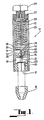
- the line pressure regulator 11 as shown at Figures 1, 2 and 3 is intended to be utilised to deliver fluid at a substantially constant pressure to a spray nozzle 10 from a high pressure fluid source that may vary in its feed pressure.
- the line regulator 11 comprises a substantially tubular housing 11 having an inlet 13 provided in its side wall at an intermediate location thereof and which opens into a first chamber 14 accommodated within the tubular body 12.
- the opposed walls of the first chamber 14 which are in opposed relation to the ends of the tubular body 12 are each formed with a first and second port 15 and 16 respectively.
- the first port 15 opens to one side of a second chamber 18 to one side of the first chamber 14 which further opens to an outlet 17 provided at one end of the tubular body 12 while the second port 16 opens the other side of the second chamber provided to the other side of the first chamber 14.
- Both sides of the second chamber 18 communicate through a fluid passageway 19 which provides a relatively unrestricted communication between the sides of the second chamber 18.
- the second chamber communicates with the outlet 17 through a third port 24.
- a spindle like support element 20 is received within the tubular housing 12 such that it is axially slidable through the ports 15 and 16.
- the support element 20 supports a set of three valve members 21, 22 and 23 which are associated with the first, second and third port 15, 16 and 24 respectively.
- the first and second valves are dimensioned such that they are slidably receivable through the respective first and second ports 15 and 16 with a very close tolerance therebetween.
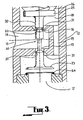
- the faces of the first and second ports 15 and 16 are fluted as shown at Figure 3 and the depths of the flutes 31 increase as the distance from the first chamber 14 increases.
- the flutes commence at a position spaced axially from the first chamber 14 while in the case of the second port 16 the flutes commence at the entry of the second port 16 into the first chamber 14.
- the flutes are relieved to minimise flow resistance, but most importantly, to guide the support element 20.
- the end of the support element 20 adjacent the outlet 17 supports the third valve member 23 which is sealingly engagable with a valve seat provided at the third port 24 when the support element 20 is located at an end position at which position the line regulator is closed.
- the other end of the support element 20 extends into the other side of the second chamber 18 and is provided with an enlarged disc-like head which is connected to a collapsible closure 26 extending between the periphery of the head 25 and a stop member 27 provided at the other end of the tubular body 12.
- a pressure spring 28 is accommodated within the collapsible closure 26 between the face of the enlarged head 25 remote from the other port 16 and the stop member 27.
- the stop member 27 is provided with a threaded stud 29 which bears against the end of the compression spring adjacent the stop 27. The extent of penetration of the stud 29 into the stop 27 serves to vary the extent of biasing force applied to the support element 20 by the spring 28.
- a portion of the support element adjacent the enlarged head 25 is formed with an increased diameter shank 30 which is snugly and slidably received by the flutes 31 in the other port 16 when the support element 20 is in its end position at which position the third valve member 23 is in engagement with the third port.
- the first valve member 21 is adjacent but clear of the outlet side of the one port 15 while the second valve member 22 is located within the first chamber 14 and is clear of the other port 16.
- the engagement of the valve members 21 and 22 and the enlarged diameter shank 30 with the respective ports 15 and 16 is not a sealing engagement at least due to the presence of the flutes 31, and as a result there is the capacity for some fluid flow therebetween when fully engaged with the respective port.
- the support element 20 On that counteracting pressure exceeding the biasing force applied by the spring 28 the support element 20 is caused to move axially within the tubular body 12 in the direction of the stop member 27 and as a result the third valve member 23 is disengaged from the third port 24 and fluid flows into the outlet to create a higher back pressure at the outlet than that which existed at the outlet before the third member valve 23 disengaged from the third port 24.
- the resultant net increase in force on the support element in a direction away from the outlet due to the balancing pressure either side of the third valve member 23 causes the support element 20 to move quickly away from the end position, to a second pressure regulating position, such that the valve members 21 and 22 are brought into engagement with ports 15 and 16 respectively to restrict the flow from the first chamber 14 to second chamber 18.
- the passageway 19 ensures that there is little pressure differential between each side of the second chamber 18.
- the pressure at the outlet side of the first and second ports in the second chamber 18 is throttled by the degree of engagement of the first and second valve 21 and 22 with the first and second ports 15 and 16. Should there be a rise in the outlet pressure, the degree of engagement increases thereby increasing throttling.
- outlet pressure is regulated to remain substantially constant irrespective of supply pressure.
- first and the second valve members 21 and 22 are brought into engagement with the ports 15 and 16 respectively to reduce the degree of communication of the fluid pressure applied to the inlet to the second chamber 18.
- both the first and second valve members 21 and 22 become fully engaged with the respective ports 15 and 16 whereby the only fluid flow through the ports is accommodated by the flutes and the clearance between the respective valve members and the respective ports.
- the value of the first embodiment may be schematically represented as shown at Figure 5.
- the supply pressure P1 produces balancing forces F1 on the first and second valves marked 21 and 22 where they are the same area A.
- the area A2 of the enlarged head 25 is greater than the area A3 of the third valve members 23.
- the differential force between the forces F2 and F3 applied to the enlarged head 25 and the third valve member 23 respectively is balanced by the force F s applied by the spring.
- the strength of the spring 28 determines the value of inlet pressure P1 required to open the line regulator.
- the pressure required to maintain the third valve member in the open is less than the pressure required to move the third valve member from the closed position.
- the new balance position of the support element is one at which the pressure in the second chamber is held at a level at which the force Fs applied by the spring is just balanced. If the pressure P2 in the second chamber continues to increase the support element is moved to bring the first and second valve members 21 and 22 into closer engagement with the first and second ports 15 and 16 respectively to further throttle the flow between the inlet chamber 14 and second chamber 18 so as to reduce P2 with respect to P1.
- the inlet pressure P1 is low (i.e. nearly equal to P2) the extent of throttling by the first and second valve member 15 and 16 is low and resistance to flow is low. If the inlet pressure P1 is much greater than the pressure P2 in the second chamber 18 the throttling by the first and second valve members 15 and 16 is greater.
- the minimal extent of movement of the spindle required to vary the extent of throttling to control the pressure P2 in the second chamber results in only a slight difference on the force F s applied by the spring 28. This implies a higher regulation of pressure for instances of a high inlet pressure than for low inlet pressures however in practice the difference in the degree of regulation has been found to be negligible.
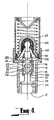
- the second embodiment as shown at Figure 4 is of a similar form to that of the first embodiment except that the enlarged head of the collapsible closure 26 and the support element 20 of the first embodiment is replaced by a flexible diaphragm 125 which may be formed of an elastomeric material which is supported by a central boss 132 receivable over the end of the support 20 element adjacent the other end of the tubular body and which receives the innermost end of the spring 28.
- tubular body is formed as a two part body while the ports 15 and 16 are accommodated within a tubular element 133 axially supported between a pair of axially opposed apertures provided in the walls of the chamber 13 whereby the tubular element 133 is formed with axial extensions 134 and 135 which slidably support the support element to each side of the ports the relief flutes 31 of the first embodiment are substituted by ports 136 in tubular element 133.
Landscapes
- Physics & Mathematics (AREA)
- Fluid Mechanics (AREA)
- General Physics & Mathematics (AREA)
- Engineering & Computer Science (AREA)
- Automation & Control Theory (AREA)
- Control Of Fluid Pressure (AREA)
- Fuel-Injection Apparatus (AREA)
- Safety Valves (AREA)
- Steering Control In Accordance With Driving Conditions (AREA)
- Electrical Discharge Machining, Electrochemical Machining, And Combined Machining (AREA)
Applications Claiming Priority (2)
| Application Number | Priority Date | Filing Date | Title |
|---|---|---|---|
| AU2965/89 | 1989-02-27 | ||
| AUPJ296589 | 1989-02-27 |
Publications (3)
| Publication Number | Publication Date |
|---|---|
| EP0385029A2 true EP0385029A2 (de) | 1990-09-05 |
| EP0385029A3 EP0385029A3 (de) | 1992-01-08 |
| EP0385029B1 EP0385029B1 (de) | 1995-03-22 |
Family
ID=3773752
Family Applications (1)
| Application Number | Title | Priority Date | Filing Date |
|---|---|---|---|
| EP89312035A Expired - Lifetime EP0385029B1 (de) | 1989-02-27 | 1989-11-21 | Leitungs-Druckregler |
Country Status (16)
| Country | Link |
|---|---|
| US (1) | US5035260A (de) |
| EP (1) | EP0385029B1 (de) |
| JP (1) | JPH0823771B2 (de) |
| KR (1) | KR0156734B1 (de) |
| CN (1) | CN1023031C (de) |
| AT (1) | ATE120289T1 (de) |
| AU (1) | AU615121B2 (de) |
| BR (1) | BR9000921A (de) |
| CA (1) | CA2011009C (de) |
| DE (1) | DE68921874T2 (de) |
| ES (1) | ES2074470T3 (de) |
| IL (1) | IL93431A (de) |
| MY (1) | MY104682A (de) |
| NZ (1) | NZ232677A (de) |
| PH (1) | PH27061A (de) |
| ZA (1) | ZA901380B (de) |
Cited By (3)
| Publication number | Priority date | Publication date | Assignee | Title |
|---|---|---|---|---|
| RU2174701C2 (ru) * | 1999-03-25 | 2001-10-10 | Целовальников Петр Герасимович | Подвижная система прямоточного сервопривода |
| RU2242787C2 (ru) * | 2002-11-12 | 2004-12-20 | Федеральное государственное унитарное предприятие Научно-производственное объединение прикладной механики им. акад.М.Ф. Решетнева | Способ регулирования давления в редукторе и устройство для его осуществления |
| RU2526900C2 (ru) * | 2009-02-26 | 2014-08-27 | Теском Корпорейшн | Встраиваемый регулятор давления |
Families Citing this family (10)
| Publication number | Priority date | Publication date | Assignee | Title |
|---|---|---|---|---|
| JP2550999Y2 (ja) * | 1991-01-09 | 1997-10-15 | 電気化学計器株式会社 | 試料液の減圧装置 |
| WO1999053388A1 (en) * | 1998-04-09 | 1999-10-21 | Glenborden Pty. Ltd. | Fluid regulator and improvements related thereto |
| US7418832B2 (en) * | 2003-10-21 | 2008-09-02 | William R Ferrono | Portable mister for adjusting ambient temperature |
| US7464532B2 (en) * | 2005-10-25 | 2008-12-16 | Woodward Governor Company | Apparatus for elimination of transient pressure spikes on stiff fluid systems |
| US7669610B2 (en) * | 2006-02-09 | 2010-03-02 | Tescom Corporation | Dome-loaded pressure regulators |
| IE86818B1 (en) * | 2011-04-11 | 2017-09-06 | Arch & Metal Systems Ltd | Two box-section beam |
| US9080687B2 (en) * | 2012-05-24 | 2015-07-14 | Honeywell International Inc. | Pressure and flow altitude compensated shutoff valve |
| FI125547B (en) * | 2014-02-19 | 2015-11-30 | Heikki Antero Pohjola | A method and arrangement for maintaining the pressure of a fluid flow in a system at a predetermined, almost constant level |
| KR102446114B1 (ko) * | 2016-11-03 | 2022-09-22 | 아드반스 덴키 고교 가부시키가이샤 | 배압 제어 밸브 |
| DE102018211995B4 (de) * | 2017-08-01 | 2020-12-10 | Siemens Aktiengesellschaft | Druckauslöser für einen elektrischen Schalter und elektrischer Schalter mit solch einem Druckauslöser |
Family Cites Families (12)
| Publication number | Priority date | Publication date | Assignee | Title |
|---|---|---|---|---|
| US417134A (en) * | 1889-12-10 | Gas-pressure regulator | ||
| US942042A (en) * | 1909-04-20 | 1909-11-30 | Benjamin H Petley | Fluid-pressure regulator. |
| US2746471A (en) * | 1952-03-29 | 1956-05-22 | Penn Controls | Pressure regulator and shut-off valve |
| CH357366A (de) * | 1957-08-28 | 1961-10-15 | Schweiz Gasapparate Fabrik Sol | Verfahren zur Betätigung einer Mangelsicherung und Gerät zur Durchführung dieses Verfahrens |
| FR1283321A (fr) * | 1960-12-23 | 1962-02-02 | Centre Nat Rech Scient | Détendeur-régulateur à soupape compensée |
| US3040765A (en) * | 1960-12-29 | 1962-06-26 | Dennis N Larkins | Relief valve |
| US3156262A (en) * | 1963-02-05 | 1964-11-10 | Atlas Copco Ab | Flow control valves |
| US3545465A (en) * | 1967-11-29 | 1970-12-08 | Vapor Corp | Pressure regulator |
| US3593742A (en) * | 1969-06-24 | 1971-07-20 | Julian S Taylor | Fluid flow regulator |
| SU798755A1 (ru) * | 1979-01-17 | 1981-01-23 | Производственное Объединение "Ждановтяжмаш" | Регул тор давлени |
| SU890370A1 (ru) * | 1979-12-17 | 1981-12-15 | Научно-Исследовательский И Конструкторско-Технологический Институт Теплоэнергетического Приборостроения | Регул тор давлени газа |
| JPS6347926Y2 (de) * | 1981-04-14 | 1988-12-09 |
-
1989
- 1989-02-27 AU AU45433/89A patent/AU615121B2/en not_active Ceased
- 1989-11-21 AT AT89312035T patent/ATE120289T1/de active
- 1989-11-21 EP EP89312035A patent/EP0385029B1/de not_active Expired - Lifetime
- 1989-11-21 ES ES89312035T patent/ES2074470T3/es not_active Expired - Lifetime
- 1989-11-21 DE DE68921874T patent/DE68921874T2/de not_active Expired - Fee Related
- 1989-11-22 US US07/440,658 patent/US5035260A/en not_active Expired - Fee Related
- 1989-12-09 MY MYPI89001734A patent/MY104682A/en unknown
-
1990
- 1990-02-19 IL IL93431A patent/IL93431A/xx not_active IP Right Cessation
- 1990-02-23 BR BR909000921A patent/BR9000921A/pt not_active IP Right Cessation
- 1990-02-23 ZA ZA901380A patent/ZA901380B/xx unknown
- 1990-02-26 NZ NZ232677A patent/NZ232677A/en unknown
- 1990-02-26 PH PH40111A patent/PH27061A/en unknown
- 1990-02-27 CN CN90101102A patent/CN1023031C/zh not_active Expired - Fee Related
- 1990-02-27 CA CA002011009A patent/CA2011009C/en not_active Expired - Fee Related
- 1990-02-27 KR KR1019900002523A patent/KR0156734B1/ko not_active Expired - Fee Related
- 1990-02-27 JP JP2049118A patent/JPH0823771B2/ja not_active Expired - Lifetime
Cited By (3)
| Publication number | Priority date | Publication date | Assignee | Title |
|---|---|---|---|---|
| RU2174701C2 (ru) * | 1999-03-25 | 2001-10-10 | Целовальников Петр Герасимович | Подвижная система прямоточного сервопривода |
| RU2242787C2 (ru) * | 2002-11-12 | 2004-12-20 | Федеральное государственное унитарное предприятие Научно-производственное объединение прикладной механики им. акад.М.Ф. Решетнева | Способ регулирования давления в редукторе и устройство для его осуществления |
| RU2526900C2 (ru) * | 2009-02-26 | 2014-08-27 | Теском Корпорейшн | Встраиваемый регулятор давления |
Also Published As
| Publication number | Publication date |
|---|---|
| MY104682A (en) | 1994-05-31 |
| EP0385029B1 (de) | 1995-03-22 |
| KR900013369A (ko) | 1990-09-05 |
| ES2074470T3 (es) | 1995-09-16 |
| CN1045166A (zh) | 1990-09-05 |
| CA2011009C (en) | 1993-11-02 |
| ATE120289T1 (de) | 1995-04-15 |
| AU4543389A (en) | 1990-08-30 |
| PH27061A (en) | 1993-02-01 |
| IL93431A0 (en) | 1990-11-29 |
| BR9000921A (pt) | 1991-02-19 |
| CN1023031C (zh) | 1993-12-08 |
| ZA901380B (en) | 1990-11-28 |
| JPH0823771B2 (ja) | 1996-03-06 |
| NZ232677A (en) | 1991-08-27 |
| AU615121B2 (en) | 1991-09-19 |
| EP0385029A3 (de) | 1992-01-08 |
| US5035260A (en) | 1991-07-30 |
| JPH02267608A (ja) | 1990-11-01 |
| DE68921874T2 (de) | 1995-11-30 |
| CA2011009A1 (en) | 1990-08-27 |
| DE68921874D1 (de) | 1995-04-27 |
| IL93431A (en) | 1993-08-18 |
| KR0156734B1 (ko) | 1998-12-15 |
Similar Documents
| Publication | Publication Date | Title |
|---|---|---|
| CA2128953C (en) | Pilot stage for pressure control valves | |
| US5035260A (en) | Line pressure regulator | |
| JP3118230B2 (ja) | パイロット作動圧力弁 | |
| JPH07151107A (ja) | フィードバックポッペト弁 | |
| US4250914A (en) | Flow regulator | |
| JPH04312227A (ja) | 振動ダンパ | |
| US4565209A (en) | Pressure regulating valve with feedback control | |
| US4250913A (en) | Pilot mechanism for pressure regulating valve | |
| US5971012A (en) | Constant flow control valve having matable piston sleeve and outlet cover | |
| US6820641B2 (en) | Internally piloted dome loaded regulator | |
| US3896844A (en) | Fluid flow regulating apparatus | |
| US4130127A (en) | Accumulator changing valve | |
| US4667695A (en) | Pressure regulating and on-off valve | |
| US4794846A (en) | Proportional action valve with a biased spring unproportionately variable to the load pressure | |
| US4630639A (en) | Apparatus for controlling pressure and flow rate | |
| US5647394A (en) | Control valve | |
| US20180024576A1 (en) | Stable Pressure Regulator Apparatus | |
| US5280805A (en) | Flow control valve having adjustable sleeve for varying flow rate | |
| US4331179A (en) | Regulator/valve controller | |
| HU177219B (en) | Pressure regulator of medium in motion | |
| US3460559A (en) | Combined pressure regulator and relief valve | |
| JP2846277B2 (ja) | チェック弁付圧力補償流量調整弁 | |
| JP2837218B2 (ja) | 前制御される減圧弁 | |
| JPH0418014Y2 (de) | ||
| EP0103349A1 (de) | Variables Druckregelventil |
Legal Events
| Date | Code | Title | Description |
|---|---|---|---|
| PUAI | Public reference made under article 153(3) epc to a published international application that has entered the european phase |
Free format text: ORIGINAL CODE: 0009012 |
|
| AK | Designated contracting states |
Kind code of ref document: A2 Designated state(s): AT BE CH DE ES FR GB GR IT LI LU NL SE |
|
| PUAL | Search report despatched |
Free format text: ORIGINAL CODE: 0009013 |
|
| AK | Designated contracting states |
Kind code of ref document: A3 Designated state(s): AT BE CH DE ES FR GB GR IT LI LU NL SE |
|
| 17P | Request for examination filed |
Effective date: 19920707 |
|
| 17Q | First examination report despatched |
Effective date: 19930928 |
|
| GRAA | (expected) grant |
Free format text: ORIGINAL CODE: 0009210 |
|
| AK | Designated contracting states |
Kind code of ref document: B1 Designated state(s): AT BE CH DE ES FR GB GR IT LI LU NL SE |
|
| PG25 | Lapsed in a contracting state [announced via postgrant information from national office to epo] |
Ref country code: NL Free format text: LAPSE BECAUSE OF NON-PAYMENT OF DUE FEES Effective date: 19950322 Ref country code: GR Free format text: LAPSE BECAUSE OF FAILURE TO SUBMIT A TRANSLATION OF THE DESCRIPTION OR TO PAY THE FEE WITHIN THE PRESCRIBED TIME-LIMIT Effective date: 19950322 Ref country code: BE Effective date: 19950322 Ref country code: AT Effective date: 19950322 |
|
| REF | Corresponds to: |
Ref document number: 120289 Country of ref document: AT Date of ref document: 19950415 Kind code of ref document: T |
|
| REF | Corresponds to: |
Ref document number: 68921874 Country of ref document: DE Date of ref document: 19950427 |
|
| ITF | It: translation for a ep patent filed | ||
| PG25 | Lapsed in a contracting state [announced via postgrant information from national office to epo] |
Ref country code: SE Effective date: 19950622 |
|
| ET | Fr: translation filed | ||
| NLV1 | Nl: lapsed or annulled due to failure to fulfill the requirements of art. 29p and 29m of the patents act | ||
| REG | Reference to a national code |
Ref country code: ES Ref legal event code: FG2A Ref document number: 2074470 Country of ref document: ES Kind code of ref document: T3 |
|
| PG25 | Lapsed in a contracting state [announced via postgrant information from national office to epo] |
Ref country code: LU Free format text: LAPSE BECAUSE OF NON-PAYMENT OF DUE FEES Effective date: 19951130 |
|
| PLBE | No opposition filed within time limit |
Free format text: ORIGINAL CODE: 0009261 |
|
| STAA | Information on the status of an ep patent application or granted ep patent |
Free format text: STATUS: NO OPPOSITION FILED WITHIN TIME LIMIT |
|
| 26N | No opposition filed | ||
| PGFP | Annual fee paid to national office [announced via postgrant information from national office to epo] |
Ref country code: GB Payment date: 19971119 Year of fee payment: 9 |
|
| PGFP | Annual fee paid to national office [announced via postgrant information from national office to epo] |
Ref country code: FR Payment date: 19971121 Year of fee payment: 9 |
|
| PGFP | Annual fee paid to national office [announced via postgrant information from national office to epo] |
Ref country code: ES Payment date: 19971128 Year of fee payment: 9 |
|
| PGFP | Annual fee paid to national office [announced via postgrant information from national office to epo] |
Ref country code: CH Payment date: 19971211 Year of fee payment: 9 |
|
| PGFP | Annual fee paid to national office [announced via postgrant information from national office to epo] |
Ref country code: DE Payment date: 19980129 Year of fee payment: 9 |
|
| PG25 | Lapsed in a contracting state [announced via postgrant information from national office to epo] |
Ref country code: GB Free format text: LAPSE BECAUSE OF NON-PAYMENT OF DUE FEES Effective date: 19981121 |
|
| PG25 | Lapsed in a contracting state [announced via postgrant information from national office to epo] |
Ref country code: ES Free format text: LAPSE BECAUSE OF NON-PAYMENT OF DUE FEES Effective date: 19981122 |
|
| PG25 | Lapsed in a contracting state [announced via postgrant information from national office to epo] |
Ref country code: LI Free format text: LAPSE BECAUSE OF NON-PAYMENT OF DUE FEES Effective date: 19981130 Ref country code: CH Free format text: LAPSE BECAUSE OF NON-PAYMENT OF DUE FEES Effective date: 19981130 |
|
| GBPC | Gb: european patent ceased through non-payment of renewal fee |
Effective date: 19981121 |
|
| REG | Reference to a national code |
Ref country code: CH Ref legal event code: PL |
|
| PG25 | Lapsed in a contracting state [announced via postgrant information from national office to epo] |
Ref country code: FR Free format text: LAPSE BECAUSE OF NON-PAYMENT OF DUE FEES Effective date: 19990730 |
|
| REG | Reference to a national code |
Ref country code: FR Ref legal event code: ST |
|
| PG25 | Lapsed in a contracting state [announced via postgrant information from national office to epo] |
Ref country code: DE Free format text: LAPSE BECAUSE OF NON-PAYMENT OF DUE FEES Effective date: 19990901 |
|
| REG | Reference to a national code |
Ref country code: ES Ref legal event code: FD2A Effective date: 19991214 |
|
| PG25 | Lapsed in a contracting state [announced via postgrant information from national office to epo] |
Ref country code: IT Free format text: LAPSE BECAUSE OF NON-PAYMENT OF DUE FEES;WARNING: LAPSES OF ITALIAN PATENTS WITH EFFECTIVE DATE BEFORE 2007 MAY HAVE OCCURRED AT ANY TIME BEFORE 2007. THE CORRECT EFFECTIVE DATE MAY BE DIFFERENT FROM THE ONE RECORDED. Effective date: 20051121 |