EP0385040A2 - Auflaufbremse für ein gezogenes Fahrzeug, zum Beispiel ein Anhänger mit automatischer Unterdrückung des Bremsens beim Rückwärtsfahren - Google Patents
Auflaufbremse für ein gezogenes Fahrzeug, zum Beispiel ein Anhänger mit automatischer Unterdrückung des Bremsens beim Rückwärtsfahren Download PDFInfo
- Publication number
- EP0385040A2 EP0385040A2 EP89403250A EP89403250A EP0385040A2 EP 0385040 A2 EP0385040 A2 EP 0385040A2 EP 89403250 A EP89403250 A EP 89403250A EP 89403250 A EP89403250 A EP 89403250A EP 0385040 A2 EP0385040 A2 EP 0385040A2
- Authority
- EP
- European Patent Office
- Prior art keywords
- jaw
- jaws
- spacer
- engages
- intermediate piece
- Prior art date
- Legal status (The legal status is an assumption and is not a legal conclusion. Google has not performed a legal analysis and makes no representation as to the accuracy of the status listed.)
- Granted
Links
Images

Classifications
-
- B—PERFORMING OPERATIONS; TRANSPORTING
- B60—VEHICLES IN GENERAL
- B60T—VEHICLE BRAKE CONTROL SYSTEMS OR PARTS THEREOF; BRAKE CONTROL SYSTEMS OR PARTS THEREOF, IN GENERAL; ARRANGEMENT OF BRAKING ELEMENTS ON VEHICLES IN GENERAL; PORTABLE DEVICES FOR PREVENTING UNWANTED MOVEMENT OF VEHICLES; VEHICLE MODIFICATIONS TO FACILITATE COOLING OF BRAKES
- B60T7/00—Brake-action initiating means
- B60T7/12—Brake-action initiating means for automatic initiation; for initiation not subject to will of driver or passenger
- B60T7/20—Brake-action initiating means for automatic initiation; for initiation not subject to will of driver or passenger specially for trailers, e.g. in case of uncoupling of or overrunning by trailer
- B60T7/203—Brake-action initiating means for automatic initiation; for initiation not subject to will of driver or passenger specially for trailers, e.g. in case of uncoupling of or overrunning by trailer with automatic brake release or reduction in case of reverse travel, e.g. by means of mechanisms mounted on the draw bar
- B60T7/206—Brake-action initiating means for automatic initiation; for initiation not subject to will of driver or passenger specially for trailers, e.g. in case of uncoupling of or overrunning by trailer with automatic brake release or reduction in case of reverse travel, e.g. by means of mechanisms mounted on the draw bar by means of mechanisms mounted on trailer drum brakes
-
- F—MECHANICAL ENGINEERING; LIGHTING; HEATING; WEAPONS; BLASTING
- F16—ENGINEERING ELEMENTS AND UNITS; GENERAL MEASURES FOR PRODUCING AND MAINTAINING EFFECTIVE FUNCTIONING OF MACHINES OR INSTALLATIONS; THERMAL INSULATION IN GENERAL
- F16D—COUPLINGS FOR TRANSMITTING ROTATION; CLUTCHES; BRAKES
- F16D51/00—Brakes with outwardly-movable braking members co-operating with the inner surface of a drum or the like
- F16D51/16—Brakes with outwardly-movable braking members co-operating with the inner surface of a drum or the like shaped as brake-shoes pivoted on a fixed or nearly-fixed axis
- F16D51/18—Brakes with outwardly-movable braking members co-operating with the inner surface of a drum or the like shaped as brake-shoes pivoted on a fixed or nearly-fixed axis with two brake-shoes
- F16D51/20—Brakes with outwardly-movable braking members co-operating with the inner surface of a drum or the like shaped as brake-shoes pivoted on a fixed or nearly-fixed axis with two brake-shoes extending in opposite directions from their pivots
-
- F—MECHANICAL ENGINEERING; LIGHTING; HEATING; WEAPONS; BLASTING
- F16—ENGINEERING ELEMENTS AND UNITS; GENERAL MEASURES FOR PRODUCING AND MAINTAINING EFFECTIVE FUNCTIONING OF MACHINES OR INSTALLATIONS; THERMAL INSULATION IN GENERAL
- F16D—COUPLINGS FOR TRANSMITTING ROTATION; CLUTCHES; BRAKES
- F16D51/00—Brakes with outwardly-movable braking members co-operating with the inner surface of a drum or the like
- F16D51/46—Self-tightening brakes with pivoted brake shoes, i.e. the braked member increases the braking action
Definitions
- the invention relates to an inertia braking device for a towed vehicle such as a trailer, and more particularly to such a device in which the braking action is automatically suppressed when moving in reverse.
- Braking devices of this type comprising, housed inside a rotating drum, two friction jaws in an arc of a circle which bear at one end on a fixed support and which are intended, during the actuation of a spacer device, to move outward to engage the rotating drum and ensure its immobilization.
- One of these jaws has a particular structure in order to be able to fade radially inwards, under the action of the drum rotating in the reverse direction, thereby eliminating the braking action and allowing the recoil of trailer.
- the present invention also relates to a device using two jaws in an arc designed to be able to move outward, but this device, which does not provide for isolated displacement of one of the two jaws and in particular no movement of radial erasure of the jaw, is fundamentally designed and operated different from those of known braking devices, allowing a significant simplification of the device, in particular at the level of the parking brake control intended to be associated with it, as well as increased braking efficiency.
- the two jaws are connected together at one end by a connecting piece slidingly mounted inside a fixed support while, at their opposite end, these jaws cooperate with a spacer device.
- the connection of one of the jaws with the spacer device is effected by means of an intermediate piece articulated on this jaw.
- the assembly consisting of the two jaws, the intermediate piece, the connecting piece and the spreader device moves en bloc in this direction of rotation until the jaw not associated with the intermediate piece engages the fixed stop.
- the rear face of the intermediate piece no longer resting on the fixed stop, this intermediate piece can then pivot relative to the associated jaw by increasing the stroke of the spacer device and therefore reducing the spacing of said associated jaw which then no longer prohibits the rotation of the wheel drum in reverse.
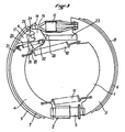
- actuation of the parking brake lever causes maximum traction on the spacer device which causes the pivoting of the intermediate piece until it engages the jaw associated with it. The spacing of this jaw is then ensured and braking is performed, whatever the direction of rotation of the wheel drum.
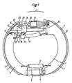
- FIG. 1 there is shown a braking device according to the invention intended to equip the wheel hub of a trailer comprising an inertia braking system.
- the braking device comprises an annular support plate 1 on which is mounted a support 2 in the form of a sleeve.
- Two arched jaws 3, 4, facing each other, are mounted on the plate 1, each having one end secured to a connecting piece 5 slidably mounted inside the support 2.
- the jaws 3, 4 cooperate with a spacer device, which will be described later.
- Each jaw 3, 4 is made up of a single element comprising an arcuate flat part, the outer edge of which is secured to an arcuate plate respectively 6, 7 of perpendicular orientation, which carries a friction lining 8, 9.
- Tension springs 10, 11 connect the jaws 3 and 4 together, opposing their spacing.
- the conventional type spacer device shown at 12, has one end engaged in a notch in the jaw 3 and is actuated from a brake cable (not shown) connected in a known manner to the inertia control device of the trailer. and the parking brake lever.
- the opposite end of the spacer device 12 engages in the notch 14 of an intermediate piece 15 which is itself articulated, around an axis 16, to an extension 17 of the jaw 4.
- On its front face the intermediate part 15 has a flat part 18 designed to be able to engage a corresponding part 19 of the jaw 4.
- a tension spring 20 connects a yoke 21 of the jaw 4 to a stud 22 carried by the lower part of the part 15.
- the annular plate 1 carries a fixed stop 23, the ends of which are intended to be engaged one by the jaw 3 and the other by the flat rear face 26 of the intermediate part 15.
- FIG. 1 it has been assumed that the wheel drum associated with the device rotates in the forward direction (direction of arrow A) and it is understood that, during braking, the jaws 3, 4 move apart under the action of the retractor and engage the drum.
- the friction action of the drum on the linings 8, 9 results in a displacement in a block, in the direction of arrow A, of the assembly formed by the jaw 4, the intermediate piece 15, the spacer 12, the jaw 3 and the connecting piece 5 (which is mounted floating inside the support 2), until the jaw 4 comes to engage the stop 23 via the rear face 26 of the piece 15.
- the part 15 is blocked between the stop 23 and the jaw 4 (of which the part 19 engages the part 18 of the front face of the part 15) and cannot therefore pivot.
- the jaw 3, spaced from the stop 23, then provides an action of effective braking.
- the jaw 4 also engages the wheel drum by increasing the braking efficiency.
- the handbrake lever (not shown) is actuated so that the brake cable pulls as far as possible on the spacer 12.
- This action causes the intermediate piece 15 to pivot in an anti-clockwise direction until that it comes to engage through the upper oblique part 24 of its front face the corresponding profile part 25 of the jaw 4.
- This stop position once reached, the actuation of the spacer 12 ensures the separation of the two jaws and immobilization of the drum in both directions of rotation.
- the device according to the invention which does not use a lining which disappears inwards in reverse, makes the use of the energy storage device necessary in the case of known brakes unnecessary.
- the intermediate part 15 has a well-defined shape with on the side of its front face, a flat part 18, intended to engage the jaw 4, and a recessed oblique part 24 engaging a part 25 of the jaw 4 when the parking brake is actuated, and on the side of its rear face a flat edge 26 engaging the fixed stop 23.
- the connecting piece 5 comprises a system for adjusting the jaws 3, 4.
Landscapes
- Engineering & Computer Science (AREA)
- General Engineering & Computer Science (AREA)
- Mechanical Engineering (AREA)
- Transportation (AREA)
- Braking Arrangements (AREA)
- Regulating Braking Force (AREA)
- Hydraulic Control Valves For Brake Systems (AREA)
Priority Applications (1)
| Application Number | Priority Date | Filing Date | Title |
|---|---|---|---|
| AT89403250T ATE92861T1 (de) | 1989-01-27 | 1989-11-24 | Auflaufbremse fuer ein gezogenes fahrzeug, zum beispiel ein anhaenger mit automatischer unterdrueckung des bremsens beim rueckwaertsfahren. |
Applications Claiming Priority (2)
| Application Number | Priority Date | Filing Date | Title |
|---|---|---|---|
| FR8901015 | 1989-01-27 | ||
| FR8901015A FR2642384B1 (fr) | 1989-01-27 | 1989-01-27 | Dispositif de freinage a inertie pour un vehicule tracte tel qu'une remorque, avec suppression automatique du freinage en marche arriere |
Publications (3)
| Publication Number | Publication Date |
|---|---|
| EP0385040A2 true EP0385040A2 (de) | 1990-09-05 |
| EP0385040A3 EP0385040A3 (en) | 1990-09-26 |
| EP0385040B1 EP0385040B1 (de) | 1993-08-11 |
Family
ID=9378168
Family Applications (1)
| Application Number | Title | Priority Date | Filing Date |
|---|---|---|---|
| EP89403250A Expired - Lifetime EP0385040B1 (de) | 1989-01-27 | 1989-11-24 | Auflaufbremse für ein gezogenes Fahrzeug, zum Beispiel ein Anhänger mit automatischer Unterdrückung des Bremsens beim Rückwärtsfahren |
Country Status (5)
| Country | Link |
|---|---|
| EP (1) | EP0385040B1 (de) |
| AT (1) | ATE92861T1 (de) |
| DE (1) | DE68908387T2 (de) |
| ES (1) | ES2044188T3 (de) |
| FR (1) | FR2642384B1 (de) |
Cited By (1)
| Publication number | Priority date | Publication date | Assignee | Title |
|---|---|---|---|---|
| GB2319314A (en) * | 1996-11-02 | 1998-05-20 | Bradley Doublelock Ltd | A trailer braking system |
Families Citing this family (2)
| Publication number | Priority date | Publication date | Assignee | Title |
|---|---|---|---|---|
| FR2743043B1 (fr) | 1995-12-29 | 1998-03-06 | Thibault Essieux Rtn Sa | Dispositif de commande de frein |
| DE202013011032U1 (de) | 2013-12-10 | 2014-02-05 | Josef Heindl | Trägheitskraftbremse mit Rückfahrautomatik für Personenkraftwagen-Anhänger |
Family Cites Families (2)
| Publication number | Priority date | Publication date | Assignee | Title |
|---|---|---|---|---|
| FR2150423B3 (de) * | 1971-08-23 | 1975-10-03 | Eberhardt Peka Fahrzeug | |
| DE8523004U1 (de) * | 1985-08-09 | 1985-09-26 | Maschinenbau Knott Eggstätt Ing. Valentin Knott, 8201 Eggstätt | Radbremse |
-
1989
- 1989-01-27 FR FR8901015A patent/FR2642384B1/fr not_active Expired - Lifetime
- 1989-11-24 AT AT89403250T patent/ATE92861T1/de not_active IP Right Cessation
- 1989-11-24 EP EP89403250A patent/EP0385040B1/de not_active Expired - Lifetime
- 1989-11-24 DE DE89403250T patent/DE68908387T2/de not_active Expired - Fee Related
- 1989-11-24 ES ES89403250T patent/ES2044188T3/es not_active Expired - Lifetime
Cited By (2)
| Publication number | Priority date | Publication date | Assignee | Title |
|---|---|---|---|---|
| GB2319314A (en) * | 1996-11-02 | 1998-05-20 | Bradley Doublelock Ltd | A trailer braking system |
| GB2319314B (en) * | 1996-11-02 | 2000-07-12 | Bradley Doublelock Ltd | Towable vehicle and braking system therefor |
Also Published As
| Publication number | Publication date |
|---|---|
| FR2642384B1 (fr) | 1991-05-10 |
| ATE92861T1 (de) | 1993-08-15 |
| FR2642384A1 (fr) | 1990-08-03 |
| DE68908387T2 (de) | 1994-03-10 |
| DE68908387D1 (de) | 1993-09-16 |
| EP0385040B1 (de) | 1993-08-11 |
| EP0385040A3 (en) | 1990-09-26 |
| ES2044188T3 (es) | 1994-01-01 |
Similar Documents
| Publication | Publication Date | Title |
|---|---|---|
| FR2493942A1 (fr) | Dispositif automatique de reglage equipant un mecanisme d'actionnement et son cable de commande | |
| WO2002044581A1 (fr) | Cylindre de frein a disque avec mecanisme de frein de parc | |
| WO1994010473A1 (fr) | Frein a tambour a actionnement mecanique | |
| EP0791144B1 (de) | Mechanische betätigungseinrichtung für eine trommelbremse | |
| EP0069657B1 (de) | Trommelbremse | |
| EP0385040B1 (de) | Auflaufbremse für ein gezogenes Fahrzeug, zum Beispiel ein Anhänger mit automatischer Unterdrückung des Bremsens beim Rückwärtsfahren | |
| EP0278834A2 (de) | Trommelbremse mit selbsttätiger Nachstellung, verriegelt bei hohen Temperaturen | |
| EP0087376A1 (de) | Vorrichtung zum Spulen von Textilmaterialien die ein Bremselement zur Stillsetzung des Wickels am Ende des Spulvorganges hat | |
| EP0061961B1 (de) | Trommelbremse mit selbsttätiger Nachstellung | |
| EP0546927A1 (de) | Handbremshebel für eine Parkbremse | |
| FR2464407A1 (fr) | Mecanisme de rattrapage automatique de l'usure pour freins a tambour | |
| FR2739827A1 (fr) | Dispositif de commande pour un frein de bicyclette, comprenant un dispositif destine a limiter la force de freinage | |
| EP1214233B1 (de) | Feststellbremse, insbesondere für ein fahrzeug mit elektrischem antrieb | |
| EP0077726A1 (de) | Trommelbremse und Strebenteil für eine derartige Bremse | |
| EP0319358B1 (de) | Trommelbremse mit selbsttätiger Nachstellung | |
| FR2673594A1 (fr) | Dispositif de freinage pour bicyclettes ou vehicules similaires. | |
| FR2636904A1 (fr) | Dispositif de freinage a inertie pour remorque, avec suppression automatique du freinage en marche arriere | |
| FR2672023A1 (fr) | Dispositif de commande a rattrapage de jeu pour frein a main d'un vehicule. | |
| EP0003452B1 (de) | Trommelbremse | |
| EP1006285A1 (de) | Selbsteinstellbare Seilzugeinrichtung, Anwendung in einer Feststellbremse eines Fahrzeugs | |
| FR2536142A1 (fr) | Frein a tambour dont le dispositif de stationnement comprend un ensemble de leviers constitue d'une paire de bras | |
| FR2698424A1 (fr) | Frein à disque coulissant à rappel élastique. | |
| FR2487770A1 (fr) | Dispositif de freinage a disque pour cyclomoteurs et motocycles | |
| FR2900747A1 (fr) | Dispositif de frein a main de stationnement de vehicule automobile, equipe de moyens de rattrapage de jeu | |
| FR2519719A1 (fr) | Frein a tambour et a patins internes, comportant un dispositif de reglage automatique |
Legal Events
| Date | Code | Title | Description |
|---|---|---|---|
| PUAI | Public reference made under article 153(3) epc to a published international application that has entered the european phase |
Free format text: ORIGINAL CODE: 0009012 |
|
| PUAL | Search report despatched |
Free format text: ORIGINAL CODE: 0009013 |
|
| AK | Designated contracting states |
Kind code of ref document: A2 Designated state(s): AT BE CH DE ES GB GR IT LI LU NL SE |
|
| AK | Designated contracting states |
Kind code of ref document: A3 Designated state(s): AT BE CH DE ES GB GR IT LI LU NL SE |
|
| 17P | Request for examination filed |
Effective date: 19901226 |
|
| 17Q | First examination report despatched |
Effective date: 19920205 |
|
| GRAA | (expected) grant |
Free format text: ORIGINAL CODE: 0009210 |
|
| AK | Designated contracting states |
Kind code of ref document: B1 Designated state(s): AT BE CH DE ES GB GR IT LI LU NL SE |
|
| PG25 | Lapsed in a contracting state [announced via postgrant information from national office to epo] |
Ref country code: GR Free format text: LAPSE BECAUSE OF FAILURE TO SUBMIT A TRANSLATION OF THE DESCRIPTION OR TO PAY THE FEE WITHIN THE PRESCRIBED TIME-LIMIT Effective date: 19930811 |
|
| REF | Corresponds to: |
Ref document number: 92861 Country of ref document: AT Date of ref document: 19930815 Kind code of ref document: T |
|
| REF | Corresponds to: |
Ref document number: 68908387 Country of ref document: DE Date of ref document: 19930916 |
|
| ITF | It: translation for a ep patent filed | ||
| PG25 | Lapsed in a contracting state [announced via postgrant information from national office to epo] |
Ref country code: LU Free format text: LAPSE BECAUSE OF NON-PAYMENT OF DUE FEES Effective date: 19931130 Ref country code: LI Effective date: 19931130 Ref country code: CH Effective date: 19931130 |
|
| GBT | Gb: translation of ep patent filed (gb section 77(6)(a)/1977) |
Effective date: 19931118 |
|
| REG | Reference to a national code |
Ref country code: ES Ref legal event code: FG2A Ref document number: 2044188 Country of ref document: ES Kind code of ref document: T3 |
|
| PLBE | No opposition filed within time limit |
Free format text: ORIGINAL CODE: 0009261 |
|
| STAA | Information on the status of an ep patent application or granted ep patent |
Free format text: STATUS: NO OPPOSITION FILED WITHIN TIME LIMIT |
|
| REG | Reference to a national code |
Ref country code: CH Ref legal event code: PL |
|
| 26N | No opposition filed | ||
| ITTA | It: last paid annual fee | ||
| EAL | Se: european patent in force in sweden |
Ref document number: 89403250.7 |
|
| PGFP | Annual fee paid to national office [announced via postgrant information from national office to epo] |
Ref country code: SE Payment date: 19961126 Year of fee payment: 8 |
|
| PGFP | Annual fee paid to national office [announced via postgrant information from national office to epo] |
Ref country code: AT Payment date: 19961128 Year of fee payment: 8 |
|
| PGFP | Annual fee paid to national office [announced via postgrant information from national office to epo] |
Ref country code: ES Payment date: 19961129 Year of fee payment: 8 Ref country code: BE Payment date: 19961129 Year of fee payment: 8 |
|
| PGFP | Annual fee paid to national office [announced via postgrant information from national office to epo] |
Ref country code: NL Payment date: 19961130 Year of fee payment: 8 |
|
| PG25 | Lapsed in a contracting state [announced via postgrant information from national office to epo] |
Ref country code: AT Free format text: LAPSE BECAUSE OF NON-PAYMENT OF DUE FEES Effective date: 19971124 |
|
| PG25 | Lapsed in a contracting state [announced via postgrant information from national office to epo] |
Ref country code: SE Free format text: LAPSE BECAUSE OF NON-PAYMENT OF DUE FEES Effective date: 19971125 Ref country code: ES Free format text: LAPSE BECAUSE OF NON-PAYMENT OF DUE FEES Effective date: 19971125 |
|
| PG25 | Lapsed in a contracting state [announced via postgrant information from national office to epo] |
Ref country code: BE Free format text: LAPSE BECAUSE OF NON-PAYMENT OF DUE FEES Effective date: 19971130 |
|
| BERE | Be: lapsed |
Owner name: S.A. THIBAULT-ESSIEUX R.T.N. Effective date: 19971130 |
|
| PG25 | Lapsed in a contracting state [announced via postgrant information from national office to epo] |
Ref country code: NL Free format text: LAPSE BECAUSE OF NON-PAYMENT OF DUE FEES Effective date: 19980601 |
|
| EUG | Se: european patent has lapsed |
Ref document number: 89403250.7 |
|
| NLV4 | Nl: lapsed or anulled due to non-payment of the annual fee |
Effective date: 19980601 |
|
| REG | Reference to a national code |
Ref country code: GB Ref legal event code: IF02 |
|
| PGFP | Annual fee paid to national office [announced via postgrant information from national office to epo] |
Ref country code: GB Payment date: 20031119 Year of fee payment: 15 |
|
| PGFP | Annual fee paid to national office [announced via postgrant information from national office to epo] |
Ref country code: DE Payment date: 20031204 Year of fee payment: 15 |
|
| REG | Reference to a national code |
Ref country code: ES Ref legal event code: FD2A Effective date: 19981212 |
|
| PG25 | Lapsed in a contracting state [announced via postgrant information from national office to epo] |
Ref country code: GB Free format text: LAPSE BECAUSE OF NON-PAYMENT OF DUE FEES Effective date: 20041124 |
|
| PG25 | Lapsed in a contracting state [announced via postgrant information from national office to epo] |
Ref country code: DE Free format text: LAPSE BECAUSE OF NON-PAYMENT OF DUE FEES Effective date: 20050601 |
|
| GBPC | Gb: european patent ceased through non-payment of renewal fee |
Effective date: 20041124 |
|
| PG25 | Lapsed in a contracting state [announced via postgrant information from national office to epo] |
Ref country code: IT Free format text: LAPSE BECAUSE OF NON-PAYMENT OF DUE FEES;WARNING: LAPSES OF ITALIAN PATENTS WITH EFFECTIVE DATE BEFORE 2007 MAY HAVE OCCURRED AT ANY TIME BEFORE 2007. THE CORRECT EFFECTIVE DATE MAY BE DIFFERENT FROM THE ONE RECORDED. Effective date: 20051124 |