EP0385103B1 - Régulateur pour moteurs à combustion interne - Google Patents
Régulateur pour moteurs à combustion interne Download PDFInfo
- Publication number
- EP0385103B1 EP0385103B1 EP90101469A EP90101469A EP0385103B1 EP 0385103 B1 EP0385103 B1 EP 0385103B1 EP 90101469 A EP90101469 A EP 90101469A EP 90101469 A EP90101469 A EP 90101469A EP 0385103 B1 EP0385103 B1 EP 0385103B1
- Authority
- EP
- European Patent Office
- Prior art keywords
- shackle
- supported
- rotational speed
- stop
- bearers
- Prior art date
- Legal status (The legal status is an assumption and is not a legal conclusion. Google has not performed a legal analysis and makes no representation as to the accuracy of the status listed.)
- Expired - Lifetime
Links
- 238000002485 combustion reaction Methods 0.000 title claims description 7
- 238000002347 injection Methods 0.000 claims description 10
- 239000007924 injection Substances 0.000 claims description 10
- 238000006073 displacement reaction Methods 0.000 claims description 2
- 230000013011 mating Effects 0.000 claims 6
- 230000003247 decreasing effect Effects 0.000 description 3
- 230000001419 dependent effect Effects 0.000 description 3
- 238000011161 development Methods 0.000 description 3
- 230000018109 developmental process Effects 0.000 description 3
- 239000000446 fuel Substances 0.000 description 3
- 230000008878 coupling Effects 0.000 description 2
- 238000010168 coupling process Methods 0.000 description 2
- 238000005859 coupling reaction Methods 0.000 description 2
- 230000001105 regulatory effect Effects 0.000 description 2
- 125000006850 spacer group Chemical group 0.000 description 2
- 230000006978 adaptation Effects 0.000 description 1
- 239000000969 carrier Substances 0.000 description 1
- 238000012937 correction Methods 0.000 description 1
- 230000000694 effects Effects 0.000 description 1
Images


Classifications
-
- F—MECHANICAL ENGINEERING; LIGHTING; HEATING; WEAPONS; BLASTING
- F02—COMBUSTION ENGINES; HOT-GAS OR COMBUSTION-PRODUCT ENGINE PLANTS
- F02D—CONTROLLING COMBUSTION ENGINES
- F02D1/00—Controlling fuel-injection pumps, e.g. of high pressure injection type
- F02D1/02—Controlling fuel-injection pumps, e.g. of high pressure injection type not restricted to adjustment of injection timing, e.g. varying amount of fuel delivered
- F02D1/08—Transmission of control impulse to pump control, e.g. with power drive or power assistance
- F02D1/10—Transmission of control impulse to pump control, e.g. with power drive or power assistance mechanical
Definitions
- the invention relates to a speed controller for internal combustion engines according to the preamble of claim 1.
- Such a speed controller is already known from DE-OS 36 41 794.
- This speed controller has a centrifugal weight adjuster which generates an actuating force corresponding to the engine speed and which acts via a control linkage on a control rod serving to control the quantity.
- a tab is arranged, in which a slide is slidably arranged, which is loaded by a starting spring in the direction of increasing injection quantity and which interacts with a full-load stop.
- an adjustment of the slide for more precise adaptation of the full load quantity to the fuel requirement of the associated internal combustion engine is only possible after dismantling the bracket and, for example, by inserting spacers between the slide and bracket, and is therefore very expensive.
- the spacers not only change the amount of fuel injected at full load, but also adjust the amount of injection in the entire operating range of the internal combustion engine, including when it is idling, which necessitates extensive corrections.
- the speed controller according to the invention with the characterizing features of claim 1 has the advantage that a simple adjustment of the counterstop is possible without the length of the tab and thus other operating values, such as the idle amount, are also adjusted.
- the configuration according to claim 2 achieves a space-saving design of the tab, and the further development according to claim 3 controls a temperature-dependent starting quantity.
- the features of claim 4 achieve a fine-step actuation of the setting shaft and the further development according to claim 5 determines the rotatability of the setting shaft within predetermined limits.
- FIG. 1 shows a simplified illustration of a speed controller
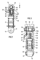
- FIG. 2 shows a first exemplary embodiment of the tab of the speed controller as a longitudinal section
- FIG. 3 shows the tab in top view
- FIG. 4 shows the tab in side view, in the direction of arrow IV in FIG. 3
- FIG 5 shows a second exemplary embodiment of the tab in plan view.
- FIG. 1 the essential parts of an idle speed controller are shown.
- the speed controller is attached to a fuel injection pump, of which only the housing 1, a camshaft 2 and a control rod serving as a quantity control element 3 are shown here.
- the camshaft 2 is driven at a speed proportional to the engine speed and drives a flyweight adjuster 4.
- the centrifugal weight adjuster 4 has two centrifugal weights 5 which move under the effect of the centrifugal forces increasing with increasing rotational speed against the forces of control springs 8 and actuate a regulating sleeve 7 via angled lever 6.
- the regulator sleeve 7 is provided with an annular groove 10 into which, as part of a regulator rod 11, an intermediate lever 12 engages at one end 12a, which is connected at its other end 12b to a tab 13 of the regulating rod 3.
- the control rod 3 can be displaced in the adjustment direction I indicated by a double arrow, a shift to the left resulting in an increasing injection quantity (+) and a displacement to the right resulting in a decreasing injection quantity (-).
- a full-load stop 15 is connected to the controller housing 14 and cooperates with a counter-stop 16 which is displaceably arranged in the bracket 13 in the adjustment direction I.
- the full load stop 15 does not have to be stationary, it can be adjusted, for example, as a function of atmospheric pressure or, if the internal combustion engine is equipped with a charger, as a function of charge air pressure.
- the tab 13 has at its end facing the intermediate lever 12 one of two fork-shaped attachments 21, each of which is provided with a cross bore 19 and has a cross bore 19.
- the end 12b of the intermediate lever 12 is arranged between the two carriers 20 and through one through the Cross bores 19 passing through bolts 22 connected to the tab 13.
- the tab 13 On its side facing the control rod 3, the tab 13 is also provided with a fork-shaped extension 24 formed by two supports 23.
- the two lugs 21 and 24 of the tab 13 are connected to one another via two brackets 25 arranged in one plane.
- the counter-stop 16 is formed by a slide 27 which is guided in a longitudinal bore 26 of the bracket 13 and a transverse bolt 29 which is fastened therein and projects through a slot 28 from the bracket 13.
- the slide 27 is supported on its end facing the control rod 3 on an adjusting shaft 30 inserted through the fork-shaped extension 24, against which it is pressed by a return spring 31 supported within the tab 13 during a warm start or by a starting spring 36 during a cold start.
- a temperature-dependent working element 34 is arranged on which a plate 35 guided in the longitudinal bore 26 is supported.
- the start spring 36 is in turn arranged between this and the slide 27.
- the working element 34 can be formed, for example, by an expansion element.
- a pin 37 protrudes from the working element 34 toward the plate 35 and engages in a countersink 38 of the plate 35.
- a guide pin 39 protrudes from the plate 35 toward the slide 27 and projects into a bore 40 in the slide 27, in which the starting spring 36 is also arranged.
- the working element 34 has a collar 41 on which the return spring 31 engages. The working element 34 is guided axially displaceably in a sleeve 42 which is held between the brackets 25.
- the setting shaft 30 has a positioning eccentric 30a in its area lying between the supports 23 and is closed with one the cross bores 19 of the carrier 23 are provided with a concentric central bore 32 through which a coupling bolt 33 is inserted for connection to the control rod 3.
- An actuating lever 43 is coupled in a rotationally secure manner to one end of the adjusting shaft 30 and has a lever arm 44 which projects radially from the adjusting shaft 30 towards the tab 13 and is cranked at its end.
- the lever arm 44 is provided with a bore 45 in its end region.
- the tab 13 has an elevation 46 with a flat surface 47 in the area in which the actuating lever 43 covers it.
- the lever arm 44 can be snapped in with a nose 49 protruding from its end face pointing towards the tab 13.
- the actuating lever 43 is provided in its area near the adjusting shaft 30 on both sides of the lever arm 44 with a stop lug 50 each.
- the length of the working element 34 is so small that the plate 35 does not abut the slide 27, but is pressed against the working element 34 by the starting spring 36.
- the cross bolt 29 of the counter-stop 16 comes to rest against the full-load stop 15
- the slide 27 is displaced against the force of the starting spring 36 in the direction of increasing injection quantity until it rests on the plate 35.
- the length of the working element 34 increases until it comes into contact with the slide 27 via the plate 35.
- the start spring 36 is now deactivated. A further expansion of the working element 34 is possible towards the sleeve 42, by compressing the return spring 31, in which the working element 34 is axially displaceable.
- a tool for rotating the actuating lever 43 can be inserted through an opening in the controller housing 14 and engages in the bore 45 of the lever arm 44.
- the setting shaft 30 can be adjusted in several stages by the actuating lever 43, the number of stages being determined by the number of longitudinal grooves 48.
- the possible adjustment of the control path of the control rod 3 can be, for example, 0.1 mm twice in the direction of increasing and in the direction of decreasing injection quantity.
- the adjusting shaft 30 is rotated such that, due to the adjusting eccentric 30 ⁇ of the adjusting shaft 30, the slide 27 together with the working element 34 against the force of the return spring 31 during a warm start or the starting spring 36 is pressed into the tab 13 during a cold start.
- the setting shaft 30 is rotated so that the effective radius of the adjusting eccentric 30 ⁇ becomes smaller, as a result of which the slide 27 is pressed closer to the setting shaft 30 again by the force of the return spring 31 or starting spring 36.
Landscapes
- Engineering & Computer Science (AREA)
- Chemical & Material Sciences (AREA)
- Combustion & Propulsion (AREA)
- Mechanical Engineering (AREA)
- General Engineering & Computer Science (AREA)
- High-Pressure Fuel Injection Pump Control (AREA)
Claims (5)
- Régulateur pour des moteurs à combustion interne comportant un régulateur centrifuge (4) servant de régulateur, une tringlerie de régulateur (11) entre un organe de dosage (3) et le régulateur centrifuge (4) permettant de modifier de manière arbitraire la quantité à injecter, une butée de charge maximale (15) reliée au boîtier du régulateur pour l'organe de dosage (3), avec une éclisse (13) servant de liaison entre d'une part l'organe de dosage (3) et d'autre part la tringlerie de régulateur (11) et une contre butée (16) coopérant avec la butée de charge maximale (15), cette contre butée coulissant dans l'éclisse (13) contre la force d'un ressort de rappel (31) s'appuyant contre l'éclisse (13), régulateur caractérisé en ce que la contre butée (16) vient en appui contre un excentrique de réglage(30a)d'un axe de réglage (30) monté transversalement à l'axe longitudinal de l'éclisse (13), par l'intermédiaire de sa face frontale dirigée vers l'extérieur, tournée vers l'un des points d'articulation (24) de l'éclisse (13), l'axe de réglage (30) pouvant tourner d'un angle de rotation limité pour le réglage fin de la contre butée (16) et cette contre butée (16) s'appuie par sa face frontale opposée à l'excentrique de réglage(30a), au moins indirectement contre l'éclisse (13) par le ressort de rappel (31).
- Régulateur selon la revendication 1, caractérisé en ce que les points d'articulation (21, 24) de l'éclisse (13) sont formés chaque fois par un prolongement en fourche à deux supports (20, 23) munis chacun d'un perçage transversal (19), les perçages (19) de deux supports (23) de l'un des points d'articulation (24) recevant l'axe de réglage (30), cet axe (30) ayant l'excentrique de réglage (30a) situé seulement dans sa partie comprise entre les deux supports (23) et cet axe comporte un perçage (32) concentrique aux perçages traversant (19) des supports (23).
- Régulateur selon la revendication 1 ou 2, caractérisé en ce que la contre butée (16) s'appuie au moins indirectement contre un élément actif (34) pour créer une quantité excédentaire pour le démarrage, par l'intermédiaire du ressort de démarrage (36) susceptible d'être comprimé, cet élément actif changeant de longueur utile en fonction de la température et s'appuyant contre l'éclisse (13) par l'intermédiaire du ressort de rappel (31), et pour éviter la quantité supplémentaire de démarrage lors du démarrage à chaud, cet élément bloque la course de départ de la contre butée (16).
- Régulateur selon l'une des revendications précédentes, caractérisé en ce qu'un levier de manoeuvre (43) est en saillie de l'axe de réglage (30) ce levier pouvant s accrocher à l'éclisse (13) dans différentes positions de rotation.
- Régulateur selon la revendication 4, caractérisé en ce que le levier de manoeuvre (43) arrive en appui contre l'éclisse (13) lorsqu'il est à un angle de rotation prédéterminé, cet angle étant limité dans les deux sens de rotation par les butée (50).
Applications Claiming Priority (2)
| Application Number | Priority Date | Filing Date | Title |
|---|---|---|---|
| DE3906142 | 1989-02-28 | ||
| DE3906142A DE3906142A1 (de) | 1989-02-28 | 1989-02-28 | Drehzahlregler fuer brennkraftmaschinen |
Publications (2)
| Publication Number | Publication Date |
|---|---|
| EP0385103A1 EP0385103A1 (fr) | 1990-09-05 |
| EP0385103B1 true EP0385103B1 (fr) | 1993-11-03 |
Family
ID=6375061
Family Applications (1)
| Application Number | Title | Priority Date | Filing Date |
|---|---|---|---|
| EP90101469A Expired - Lifetime EP0385103B1 (fr) | 1989-02-28 | 1990-01-25 | Régulateur pour moteurs à combustion interne |
Country Status (3)
| Country | Link |
|---|---|
| EP (1) | EP0385103B1 (fr) |
| JP (1) | JPH02259246A (fr) |
| DE (2) | DE3906142A1 (fr) |
Family Cites Families (1)
| Publication number | Priority date | Publication date | Assignee | Title |
|---|---|---|---|---|
| US4782804A (en) * | 1985-12-06 | 1988-11-08 | Robert Bosch Gmbh | Centrifugal speed governor for internal combustion engines |
-
1989
- 1989-02-28 DE DE3906142A patent/DE3906142A1/de not_active Withdrawn
-
1990
- 1990-01-25 EP EP90101469A patent/EP0385103B1/fr not_active Expired - Lifetime
- 1990-01-25 DE DE90101469T patent/DE59003275D1/de not_active Expired - Fee Related
- 1990-02-23 JP JP2041356A patent/JPH02259246A/ja active Pending
Also Published As
| Publication number | Publication date |
|---|---|
| DE59003275D1 (de) | 1993-12-09 |
| EP0385103A1 (fr) | 1990-09-05 |
| JPH02259246A (ja) | 1990-10-22 |
| DE3906142A1 (de) | 1990-08-30 |
Similar Documents
| Publication | Publication Date | Title |
|---|---|---|
| DE2521827C3 (de) | Regeleinrichtung für eine Kraftstoffeinspritzpumpe einer selbstzündenden Brennkraftmaschine | |
| DE2308260C2 (de) | Fliehkraftdrehzahlregler für Einspritzbrennkraftmaschinen | |
| DE2945484C2 (fr) | ||
| DE2239372A1 (de) | Fliehkraftdrehzahlregler fuer einspritzbrennkraftmaschinen | |
| EP0249615B1 (fr) | Regulateur de vitesse centrifuge pour moteurs a combustion interne | |
| DE2639961A1 (de) | Drehzahlregler fuer einspritzbrennkraftmaschinen | |
| DE2716696A1 (de) | Einrichtung zur aenderung des einspritzzeitpunktes einer kraftstoffeinspritzpumpe fuer brennkraftmaschinen | |
| DE2731107A1 (de) | Steuereinrichtung fuer aufgeladene einspritzbrennkraftmaschinen | |
| DE2757404C2 (fr) | ||
| DE3313632C2 (de) | Leerlauf-Enddrehzahlregler für Einspritzpumpen an Brennkraftmaschinen | |
| EP0385103B1 (fr) | Régulateur pour moteurs à combustion interne | |
| DE3246856C2 (fr) | ||
| EP0168586B1 (fr) | Pompe d'injection de combustible | |
| EP0029019B1 (fr) | Installation de régulation pour moteurs à combustion interne | |
| EP0204117A1 (fr) | Pompe à injection de combustible pour moteurs à combustion interne | |
| DE4129837C2 (de) | Drehzahlregler für Kraftstoffeinspritzpumpen von Brennkraftmaschinen | |
| EP0543965B1 (fr) | Regulateur pour moteurs a combustion interne | |
| DE2938200A1 (de) | Fliehkraftdrehzahlregler fuer einspritzbrennkraftmaschinen | |
| EP0438651B1 (fr) | Régulateur mécanique de vitesse pour une pompe d'injection de combustible des moteurs à compression d'air et à autoallumage | |
| EP0158846B1 (fr) | Régulateur centrifuge pour moteurs à combustion interne à injection de combustible | |
| DE4209956A1 (de) | Drehzahlregler für Kraftstoffeinspritzpumpen | |
| EP0320617A2 (fr) | Régulateur pour pompes à injection de combustible | |
| DE2909556A1 (de) | Kraftstoffeinspritzpumpe fuer brennkraftmaschinen | |
| DE864782C (de) | Regler fuer Einspritzbrennkraftmaschinen | |
| EP0425801B1 (fr) | Régulateur de vitesse centrifuge pour moteurs à combustion interne |
Legal Events
| Date | Code | Title | Description |
|---|---|---|---|
| PUAI | Public reference made under article 153(3) epc to a published international application that has entered the european phase |
Free format text: ORIGINAL CODE: 0009012 |
|
| AK | Designated contracting states |
Kind code of ref document: A1 Designated state(s): DE FR GB IT |
|
| 17P | Request for examination filed |
Effective date: 19901219 |
|
| RAP3 | Party data changed (applicant data changed or rights of an application transferred) |
Owner name: ROBERT BOSCH GMBH |
|
| 17Q | First examination report despatched |
Effective date: 19920601 |
|
| GRAA | (expected) grant |
Free format text: ORIGINAL CODE: 0009210 |
|
| AK | Designated contracting states |
Kind code of ref document: B1 Designated state(s): DE FR GB IT |
|
| ET | Fr: translation filed | ||
| REF | Corresponds to: |
Ref document number: 59003275 Country of ref document: DE Date of ref document: 19931209 |
|
| GBT | Gb: translation of ep patent filed (gb section 77(6)(a)/1977) |
Effective date: 19931112 |
|
| ITF | It: translation for a ep patent filed | ||
| PG25 | Lapsed in a contracting state [announced via postgrant information from national office to epo] |
Ref country code: GB Effective date: 19940203 |
|
| PLBE | No opposition filed within time limit |
Free format text: ORIGINAL CODE: 0009261 |
|
| STAA | Information on the status of an ep patent application or granted ep patent |
Free format text: STATUS: NO OPPOSITION FILED WITHIN TIME LIMIT |
|
| GBPC | Gb: european patent ceased through non-payment of renewal fee |
Effective date: 19940203 |
|
| PG25 | Lapsed in a contracting state [announced via postgrant information from national office to epo] |
Ref country code: FR Effective date: 19940930 |
|
| PG25 | Lapsed in a contracting state [announced via postgrant information from national office to epo] |
Ref country code: DE Effective date: 19941001 |
|
| 26N | No opposition filed | ||
| REG | Reference to a national code |
Ref country code: FR Ref legal event code: ST |
|
| PG25 | Lapsed in a contracting state [announced via postgrant information from national office to epo] |
Ref country code: IT Free format text: LAPSE BECAUSE OF NON-PAYMENT OF DUE FEES;WARNING: LAPSES OF ITALIAN PATENTS WITH EFFECTIVE DATE BEFORE 2007 MAY HAVE OCCURRED AT ANY TIME BEFORE 2007. THE CORRECT EFFECTIVE DATE MAY BE DIFFERENT FROM THE ONE RECORDED. Effective date: 20050125 |