EP0385145B1 - Procédé de charger un accumulor de plomb - Google Patents
Procédé de charger un accumulor de plomb Download PDFInfo
- Publication number
- EP0385145B1 EP0385145B1 EP90102365A EP90102365A EP0385145B1 EP 0385145 B1 EP0385145 B1 EP 0385145B1 EP 90102365 A EP90102365 A EP 90102365A EP 90102365 A EP90102365 A EP 90102365A EP 0385145 B1 EP0385145 B1 EP 0385145B1
- Authority
- EP
- European Patent Office
- Prior art keywords
- charging
- current
- voltage
- time
- cell
- Prior art date
- Legal status (The legal status is an assumption and is not a legal conclusion. Google has not performed a legal analysis and makes no representation as to the accuracy of the status listed.)
- Expired - Lifetime
Links
Images
Classifications
-
- H—ELECTRICITY
- H01—ELECTRIC ELEMENTS
- H01M—PROCESSES OR MEANS, e.g. BATTERIES, FOR THE DIRECT CONVERSION OF CHEMICAL ENERGY INTO ELECTRICAL ENERGY
- H01M10/00—Secondary cells; Manufacture thereof
- H01M10/42—Methods or arrangements for servicing or maintenance of secondary cells or secondary half-cells
- H01M10/44—Methods for charging or discharging
-
- H—ELECTRICITY
- H02—GENERATION; CONVERSION OR DISTRIBUTION OF ELECTRIC POWER
- H02J—ELECTRIC POWER NETWORKS; CIRCUIT ARRANGEMENTS OR SYSTEMS FOR SUPPLYING OR DISTRIBUTING ELECTRIC POWER; SYSTEMS FOR STORING ELECTRIC ENERGY
- H02J7/00—Circuit arrangements for charging or discharging batteries or for supplying loads from batteries
- H02J7/90—Regulation of charging or discharging current or voltage
- H02J7/96—Regulation of charging or discharging current or voltage in response to battery voltage
-
- Y—GENERAL TAGGING OF NEW TECHNOLOGICAL DEVELOPMENTS; GENERAL TAGGING OF CROSS-SECTIONAL TECHNOLOGIES SPANNING OVER SEVERAL SECTIONS OF THE IPC; TECHNICAL SUBJECTS COVERED BY FORMER USPC CROSS-REFERENCE ART COLLECTIONS [XRACs] AND DIGESTS
- Y02—TECHNOLOGIES OR APPLICATIONS FOR MITIGATION OR ADAPTATION AGAINST CLIMATE CHANGE
- Y02E—REDUCTION OF GREENHOUSE GAS [GHG] EMISSIONS, RELATED TO ENERGY GENERATION, TRANSMISSION OR DISTRIBUTION
- Y02E60/00—Enabling technologies; Technologies with a potential or indirect contribution to GHG emissions mitigation
- Y02E60/10—Energy storage using batteries
Definitions
- the invention relates to a method for charging an accumulator battery of the lead-acid type with a freely movable electrolyte, in which the charging current is gradually reduced when a gassing voltage is reached.
- the aim of all charging methods is to achieve a full charge of the battery in the shortest possible time. This usually takes place in several stages, for example according to an IUI characteristic curve, one charging initially with a relatively high, constant current, if necessary accepting early gassing, until the battery voltage reaches the actual value of the gassing voltage - in the case of lead accumulators 2.4 volts / cell - has been reached. From then on, the voltage is kept constant, and the charging current drops due to the growing counter voltage. The second charging stage is complete when the charging current has dropped to the so-called recharging current, which is only a fraction of the initial charging current. With the recharging current now kept constant, which causes the charging voltage to rise again, a time-limited recharging is carried out in the third charging stage.
- Charging techniques are now known for lead accumulators as well as for alkaline accumulators (see e.g. DE-PS 1 233 934 or DE-PS 1800 230), according to which the charge absorption during the first phase is apparently more effective when the voltage-controlled constant current charging is gradual, namely with a reduced charging current in a second phase.
- Such charging methods can also be found in DE-OS 35 07 223. There it is proposed in particular to reduce the charging current in several stages, for example in accordance with an exponential function.
- the invention is based on the object of specifying a charging method for lead batteries, in particular a “tailor-made” charging rule, which makes it possible to operate the lead battery virtually without maintenance.
- the object is achieved by a charging method as defined in claim 1.
- a complete and capacity-stable recharging is also achieved without the recharging mentioned above, even those batteries which have been exhaustively or repeatedly exhausted in cyclical charging / discharging operation, ie have given up to 100% of their nominal capacity.
- i1 should be approximately 1.25 ⁇ I5 or 0.25 CA.
- the preferred charging current i2 is about 0.75 ⁇ I5 or 0.15 CA.
- Maintaining the second voltage limit U2 reached finally follows as a third charging stage a constant voltage charging with decaying charging current, which is ended by a timer.
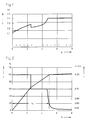
- a time t drop results, which has elapsed since the start of charging when this event occurs.
- a is an "extension factor" with a numerical value between 1 and 2, preferably 1.35
- K is an additive timing element, the numerical value of which is 0.5 to 5, preferably approximately 1.5.
- the total charging time within which the battery is fully charged with minimal water consumption is defined with t total . Furthermore, since t waste is a measure of the previous capacity draw, the amount of electricity to be loaded is optimally adapted to the previous discharge using the time function.
- t total according to the new charging method is about 8 hours if the battery was previously fully discharged.
- the charging process corresponds to an I o IU charge, in which the stronger initial current I 1 is automatically switched to I 2 after the charging voltage U 1 has been reached.
- the voltage limit values U 1 and U 2 can be adapted to the prevailing battery temperature, since the charging voltage of the lead accumulator increases with falling temperature, which is due to the poorer charge absorption.
- the charger adjusts the control or charging voltage according to the battery temperature based on a voltage / temperature characteristic curve that was obtained from experimentally determined value pairs of the cell voltage and the temperature and has been entered.
- the battery according to the invention with its constant current charge with graded currents in connection with an electrolyte circulation ensures that the charge gases are composed from the beginning so that their stoichiometry largely corresponds to that of the oxyhydrogen gas.
- This predestines the invention especially for accumulators that are to be operated with a recombiner, because this only works with the optimal efficiency under the given condition.
- the recombiner is not an absolutely necessary device for maintenance-free operation of the new battery according to the new charging process.
- electrolyte movement is indispensable. They constantly compensate for differences in concentration in the electrolyte, counteract the formation of an acid stratification, and even out the condition of the electrode plates with regard to the charge progress over the entire surface area.
- This enables the charging treatment to be refined in such a way that the charge currents according to the scheme specified according to the invention can be used to take up a charge which is optimal with regard to the currents used and the charging time.
- the efficiency of the charge is expressed in the fact that the gas formation in the main charging phase up to the switch-off point at 2.40 volts is very low in comparison to the charging methods previously used.
- the accumulator cell or battery is proving itself at this time, i.e. at the transition from the I to the U charge, already almost fully charged and then only takes up a few percent of its nominal capacity until the end of the charge.
- an external gas pump usually an air pump
- an air pump is advantageously used, which produces a bubble flow in the electrolyte space. Since in this case water losses do not only occur through electrolysis, but in addition a water discharge due to the different water vapor partial pressures between the circulating air and the sulfuric acid can take place, an acid circulation that is only operated at intervals has proven to be expedient and sufficient, for example at intervals of time 0.3 h to 1 h is started. Circulations in 1/2-hour intervals, which then each 1 min. up to 10 min last for.
- a gas pump mechanical, electrically driven pumps arranged in the accumulator can also be used.
- a water loss of approx. 4.0 g / cell was measured on a test battery with a nominal capacity of 400 Ah for a complete charge / discharge cycle (15 acid circulations during the 8-hour charging period).
- the circulation-related water discharge contained therein is comparatively low at approx. 10%.
- the use of degassing plugs made of microporous plastic that do not allow acid or water mist to pass through can further minimize water discharge.
- the charger switches to this voltage value, and the third stage is a constant voltage charge at which the charging current drops.
- markings are entered along the time axis in monotonous order. These each symbolize an acid circulation of 1 min that was started by the pump at the relevant time. Duration.
- This area now defines on the time axis the end of a charging time t drop , designated t A in the figure, and the correspondingly weakened current signals to the charger that the battery has just reached full charge at this point in time.
- t A is therefore the time sufficient to return the full nominal capacity to the battery.
- K the constant timing element K of approx. 1 1/2 h Duration (not shown in Figure 2).
- the battery according to the invention works extremely low in gassing, and an almost stoichiometric gas development is achieved under almost all operating conditions.
- the gentle charging process also leads to an extended service life.
- the low-gassing battery operation with the help of the new charging process justifies the minimal water loss, which can be reduced even further if a recombiner is advantageously used.
- the new accumulator can finally be equipped with an appropriate display device.
- the charging process can be carried out in a particularly advantageous manner in conjunction with the battery, charger and circulation pump, in such a way that the operation of the circulation pump is also controlled by the charger, which regulates voltage, current and charging time.
- the measurement data determined so far on a multi-cell test battery give rise to the expectation that maintenance-free operation of 1 year duration or. operation over 200 charge / discharge cycles is possible without loss of capacity and without water refilling. The initial state can then be restored by replenishing the water.
Landscapes
- Engineering & Computer Science (AREA)
- Secondary Cells (AREA)
- Power Engineering (AREA)
- Manufacturing & Machinery (AREA)
- Chemical & Material Sciences (AREA)
- Chemical Kinetics & Catalysis (AREA)
- Electrochemistry (AREA)
- General Chemical & Material Sciences (AREA)
- Charge And Discharge Circuits For Batteries Or The Like (AREA)
- Battery Electrode And Active Subsutance (AREA)
Claims (8)
- Procédé pour charger une batterie d'accumulateur du type au plomb, avec un électrolyte librement mobile, dans laquelle l'intensité du courant de charge est respectivement réduite par étapes lorsqu'on atteint une tension de début de dégagement gazeux, procédé caractérisé en ce que pour avoir une complète recharge de la batterie, on charge dans une première phase avec une intensité constante i₁,


 - a est un facteur numérique compris entre 1 et 2, et égal de préférence à environ 1,35,- tchute est la durée de la charge qui s'est déjà écoulée jusqu'à l'instant auquel l'intensité décroissante de la charge est tombée à une valeur comprise entre 0,1.I₅ et 0,4.I₅ et est de préférence égale à environ 0,25.I₅ et- K est une constante numérique comprise entre 0,5 et 5 et est de préférence égale à environ 1,5 et en ce que pendant au moins une partie de la durée de la charge, on brasse l'électrolyte.
 - Procédé selon la revendication 1, caractérisé en ce que l'électrolyte est brassé à intervalles d'environ 0,3 à 1 h, de préférence d'environ 0,5 h respectivement pendant 1 à 10 minutes.
- Procédé selon les revendications 1 et 2, caractérisé en ce que l'électrolyte est brassé au moyen d'un écoulement à bulles produit par une pompe extérieure à gaz.
- Procédé selon l'une des revendications 1 à 3, caractérisé en ce qu'en se basant sur la relation de température suivante :


- Procédé selon l'une des revendications 1 à 3, caractérisé en ce qu'en se basant sur la relation de température suivante :

- Procédé selon l'une des revendications 1 à 5, caractérisé en ce que le fonctionnement de la pompe de brassage soit commandé par l'appareil de charge, qui règle la tension, l'intensité et la durée de la charge.
- Procédé selon l'une des revendications 1 à 6, caractérisé en ce qu'à partir des gaz se dégageant lors de la charge, on sépare les nuages d'acide au moyen d'un bouchon de fermeture perméable au gaz, mais par contre imperméable aux liquides.
- Procédé selon l'une des revendications 1 à 7, caractérisé en ce que les gaz d'hydrogène et d'oxygène qui se dégagent pendant le charge sont réunis catalytiquement dans un recombinateur.
Applications Claiming Priority (4)
| Application Number | Priority Date | Filing Date | Title |
|---|---|---|---|
| DE3906147 | 1989-02-28 | ||
| DE3906147 | 1989-02-28 | ||
| DE3909870 | 1989-03-25 | ||
| DE3909870A DE3909870A1 (de) | 1989-02-28 | 1989-03-25 | Akkumulatorenbatterie sowie verfahren zu ihrem betrieb |
Publications (3)
| Publication Number | Publication Date |
|---|---|
| EP0385145A2 EP0385145A2 (fr) | 1990-09-05 |
| EP0385145A3 EP0385145A3 (fr) | 1993-01-13 |
| EP0385145B1 true EP0385145B1 (fr) | 1995-04-19 |
Family
ID=25878251
Family Applications (1)
| Application Number | Title | Priority Date | Filing Date |
|---|---|---|---|
| EP90102365A Expired - Lifetime EP0385145B1 (fr) | 1989-02-28 | 1990-02-07 | Procédé de charger un accumulor de plomb |
Country Status (4)
| Country | Link |
|---|---|
| EP (1) | EP0385145B1 (fr) |
| AT (1) | ATE121566T1 (fr) |
| DE (2) | DE3909870A1 (fr) |
| ES (1) | ES2072929T3 (fr) |
Families Citing this family (13)
| Publication number | Priority date | Publication date | Assignee | Title |
|---|---|---|---|---|
| AT406719B (de) * | 1991-06-05 | 2000-08-25 | Enstore Forschungs Entwicklung | Verfahren zum vorzugsweisen schnellen laden von batterien |
| DE4137866A1 (de) * | 1991-11-11 | 1993-05-19 | Gerhard Dr Lehmann | Verfahren zum laden wiederaufladbarer galvanischer batterien |
| GB2266016B (en) * | 1992-04-07 | 1995-12-13 | Cmp Batteries Ltd | Battery charging |
| US5422559A (en) * | 1993-12-06 | 1995-06-06 | Motorola, Inc. | Pulsed battery charger circuit |
| DE4402716C2 (de) * | 1994-01-29 | 1996-08-29 | Ibm | Abschätzung der Lebensdauer und der Kapazität eines Energiespeichers |
| US5623195A (en) * | 1994-06-22 | 1997-04-22 | Lucent Technologies Inc. | Apparatus and method for controlling a charging voltage of a battery based on battery temperature |
| FR2789805A1 (fr) * | 1999-02-15 | 2000-08-18 | Cit Alcatel | Procede de charge d'un generateur electrochimique |
| DK199901782A (da) * | 1999-12-14 | 2001-06-15 | J K Medico Aps | Metode til hurtig opladning af tæt kapslede batterier |
| US6326769B1 (en) * | 2000-11-29 | 2001-12-04 | Telefonaktiebolaget Lm Ericsson (Publ) | Limitation of power dissipation in Li battery |
| US6844705B2 (en) * | 2002-12-09 | 2005-01-18 | Intersil Americas Inc. | Li-ion/Li-polymer battery charger configured to be DC-powered from multiple types of wall adapters |
| DE102005006303B4 (de) * | 2005-02-11 | 2012-09-20 | Industrie Automation Energiesysteme Ag | Einrichtung zur Überwachung der Gasungsspannung von Akkumulatoren |
| ES2272187B1 (es) * | 2005-10-07 | 2008-02-16 | Quick Energy, S.L. | Procedimiento y cargador para la recarga de baterias de potencia, tales como baterias de traccion. |
| US9722334B2 (en) * | 2010-04-07 | 2017-08-01 | Black & Decker Inc. | Power tool with light unit |
Family Cites Families (3)
| Publication number | Priority date | Publication date | Assignee | Title |
|---|---|---|---|---|
| FR2239773A1 (en) * | 1973-07-03 | 1975-02-28 | Scient Electric | Electric battery charger - has initial intensive charging followed by two levels at reduced charging |
| DE3049211A1 (de) * | 1980-12-27 | 1982-07-29 | Varta Batterie Ag, 3000 Hannover | Verfahren zur regelung des ladestromes von galvanischen elementen mit rekombination der beim laden entstehenden gase |
| DE3507223A1 (de) * | 1985-03-01 | 1986-09-04 | Ernst Dr. 3000 Hannover Maier | Verfahren zum laden von akkumulatoren in zwei ladephasen |
-
1989
- 1989-03-25 DE DE3909870A patent/DE3909870A1/de not_active Withdrawn
-
1990
- 1990-02-07 DE DE59008912T patent/DE59008912D1/de not_active Expired - Lifetime
- 1990-02-07 AT AT90102365T patent/ATE121566T1/de not_active IP Right Cessation
- 1990-02-07 EP EP90102365A patent/EP0385145B1/fr not_active Expired - Lifetime
- 1990-02-07 ES ES90102365T patent/ES2072929T3/es not_active Expired - Lifetime
Also Published As
| Publication number | Publication date |
|---|---|
| DE3909870A1 (de) | 1990-08-30 |
| EP0385145A2 (fr) | 1990-09-05 |
| ES2072929T3 (es) | 1995-08-01 |
| EP0385145A3 (fr) | 1993-01-13 |
| ATE121566T1 (de) | 1995-05-15 |
| DE59008912D1 (de) | 1995-05-24 |
Similar Documents
| Publication | Publication Date | Title |
|---|---|---|
| EP0308653B1 (fr) | Procédé de charge pour batteries sans entretien avec électrolyte immobilisé | |
| EP1160953B1 (fr) | Procédé de charge d'une batterie | |
| DE3687655T2 (de) | Regelung des ladens von unter druck stehenden, elektrischen gas-metall-ladungszellen. | |
| EP0385145A2 (fr) | Procédé de charger un accumulor de plomb | |
| DE69409863T2 (de) | Batterieladegerät | |
| EP0584362A4 (en) | Method for charging battery and apparatus therefor | |
| DE19959430A1 (de) | Ladegerät und Ladeverfahren für die Batterie eines Elektrofahrzeuges | |
| DE102018131035A1 (de) | Brennstoffzellensystem und verfahren zur steuerung eines brennstoffzellensystems | |
| DE1671775C3 (de) | Gasdichter Akkumulator | |
| DE1020391B (de) | Verfahren zur Herstellung eines staendig gasdicht verschlossenen elektrischen Akkumulators sowie nach dem Verfahren hergestellter Akkumulator | |
| EP3168957B1 (fr) | Procédé et dispositif de gestion d'énergie d'un accumulateur d'énergie pour éviter les microcycles | |
| DE69830888T2 (de) | Verfahren zum temperaturabhängigen Laden einer Hilfsstromquelle welche einer Selbstentladung unterliegt | |
| DE10223557A1 (de) | Verfahren zur Pflege einer wiederaufladbaren Batterie | |
| EP0024633B1 (fr) | Accumulateur sans dégagement de gaz | |
| DE3049211C2 (fr) | ||
| DE4311586A1 (de) | Verfahren zum Laden von Bleiakkumulatoren mit festgelegtem Elektrolyten | |
| DE69017782T2 (de) | Natrium-Schwefelzelle und Verfahren zur Herstellung derselben. | |
| EP0994549B1 (fr) | Procédé pour charger des batteries | |
| DE3218148A1 (de) | Verfahren und geraet zur anzeige des ladezustandes und zur steuerung der aufladung eines antriebsakkumulators | |
| DE8906689U1 (de) | Ladegerät zum Wiederaufladen einer Sekundärzelle mit einer Li-CuCl↓2↓-Verknüpfung | |
| EP0391242A2 (fr) | Méthode d'inspection du degré de charge d'une batterie fermée rechargeable | |
| DE3717478C2 (fr) | ||
| DE2903244C3 (de) | Verfahren zum Laden einer ventilierten, einen alkalischen Elektrolyten enthaltenden elektrochemischen Zelle | |
| DE2819584A1 (de) | Schaltung zur sicherung von speicherzellen | |
| DE19833096C5 (de) | Verfahren zum Laden eines Akkumulators |
Legal Events
| Date | Code | Title | Description |
|---|---|---|---|
| PUAI | Public reference made under article 153(3) epc to a published international application that has entered the european phase |
Free format text: ORIGINAL CODE: 0009012 |
|
| AK | Designated contracting states |
Kind code of ref document: A2 Designated state(s): AT DE ES FR GB IT NL SE |
|
| PUAL | Search report despatched |
Free format text: ORIGINAL CODE: 0009013 |
|
| AK | Designated contracting states |
Kind code of ref document: A3 Designated state(s): AT DE ES FR GB IT NL SE |
|
| 17P | Request for examination filed |
Effective date: 19930126 |
|
| 17Q | First examination report despatched |
Effective date: 19940222 |
|
| GRAA | (expected) grant |
Free format text: ORIGINAL CODE: 0009210 |
|
| ITF | It: translation for a ep patent filed | ||
| AK | Designated contracting states |
Kind code of ref document: B1 Designated state(s): AT DE ES FR GB IT NL SE |
|
| PG25 | Lapsed in a contracting state [announced via postgrant information from national office to epo] |
Ref country code: NL Free format text: LAPSE BECAUSE OF FAILURE TO SUBMIT A TRANSLATION OF THE DESCRIPTION OR TO PAY THE FEE WITHIN THE PRESCRIBED TIME-LIMIT Effective date: 19950419 |
|
| REF | Corresponds to: |
Ref document number: 121566 Country of ref document: AT Date of ref document: 19950515 Kind code of ref document: T |
|
| ET | Fr: translation filed | ||
| GBT | Gb: translation of ep patent filed (gb section 77(6)(a)/1977) |
Effective date: 19950420 |
|
| REF | Corresponds to: |
Ref document number: 59008912 Country of ref document: DE Date of ref document: 19950524 |
|
| REG | Reference to a national code |
Ref country code: ES Ref legal event code: FG2A Ref document number: 2072929 Country of ref document: ES Kind code of ref document: T3 |
|
| NLV1 | Nl: lapsed or annulled due to failure to fulfill the requirements of art. 29p and 29m of the patents act | ||
| PG25 | Lapsed in a contracting state [announced via postgrant information from national office to epo] |
Ref country code: AT Effective date: 19960207 |
|
| PGFP | Annual fee paid to national office [announced via postgrant information from national office to epo] |
Ref country code: ES Payment date: 19960207 Year of fee payment: 7 |
|
| PLBE | No opposition filed within time limit |
Free format text: ORIGINAL CODE: 0009261 |
|
| STAA | Information on the status of an ep patent application or granted ep patent |
Free format text: STATUS: NO OPPOSITION FILED WITHIN TIME LIMIT |
|
| 26N | No opposition filed | ||
| REG | Reference to a national code |
Ref country code: FR Ref legal event code: TP |
|
| PG25 | Lapsed in a contracting state [announced via postgrant information from national office to epo] |
Ref country code: ES Free format text: LAPSE BECAUSE OF NON-PAYMENT OF DUE FEES Effective date: 19970208 |
|
| REG | Reference to a national code |
Ref country code: GB Ref legal event code: 732E |
|
| REG | Reference to a national code |
Ref country code: ES Ref legal event code: FD2A Effective date: 19990201 |
|
| REG | Reference to a national code |
Ref country code: FR Ref legal event code: CD |
|
| REG | Reference to a national code |
Ref country code: GB Ref legal event code: IF02 |
|
| PGFP | Annual fee paid to national office [announced via postgrant information from national office to epo] |
Ref country code: DE Payment date: 20090206 Year of fee payment: 20 |
|
| PGFP | Annual fee paid to national office [announced via postgrant information from national office to epo] |
Ref country code: GB Payment date: 20090204 Year of fee payment: 20 |
|
| PGFP | Annual fee paid to national office [announced via postgrant information from national office to epo] |
Ref country code: IT Payment date: 20090218 Year of fee payment: 20 Ref country code: SE Payment date: 20090206 Year of fee payment: 20 |
|
| PGFP | Annual fee paid to national office [announced via postgrant information from national office to epo] |
Ref country code: FR Payment date: 20090213 Year of fee payment: 20 |
|
| REG | Reference to a national code |
Ref country code: GB Ref legal event code: PE20 Expiry date: 20100206 |
|
| PG25 | Lapsed in a contracting state [announced via postgrant information from national office to epo] |
Ref country code: GB Free format text: LAPSE BECAUSE OF EXPIRATION OF PROTECTION Effective date: 20100206 |
|
| PG25 | Lapsed in a contracting state [announced via postgrant information from national office to epo] |
Ref country code: DE Free format text: LAPSE BECAUSE OF EXPIRATION OF PROTECTION Effective date: 20100207 |