EP0385236A2 - Epandeur d'engrais à projection centrifuge - Google Patents
Epandeur d'engrais à projection centrifuge Download PDFInfo
- Publication number
- EP0385236A2 EP0385236A2 EP90103231A EP90103231A EP0385236A2 EP 0385236 A2 EP0385236 A2 EP 0385236A2 EP 90103231 A EP90103231 A EP 90103231A EP 90103231 A EP90103231 A EP 90103231A EP 0385236 A2 EP0385236 A2 EP 0385236A2
- Authority
- EP
- European Patent Office
- Prior art keywords
- centrifugal
- adjustable
- broadcaster according
- disc
- operating position
- Prior art date
- Legal status (The legal status is an assumption and is not a legal conclusion. Google has not performed a legal analysis and makes no representation as to the accuracy of the status listed.)
- Granted
Links
Images


Classifications
-
- A—HUMAN NECESSITIES
- A01—AGRICULTURE; FORESTRY; ANIMAL HUSBANDRY; HUNTING; TRAPPING; FISHING
- A01C—PLANTING; SOWING; FERTILISING
- A01C17/00—Fertilisers or seeders with centrifugal wheels
- A01C17/006—Regulating or dosing devices
- A01C17/008—Devices controlling the quantity or the distribution pattern
Definitions
- the invention relates to a centrifugal spreader for fertilizers, consisting of a storage container with two adjustable outlet openings arranged at a distance from one another, and one centrifugal disk arranged under each outlet opening, which is driven by a hydraulic motor at a variable speed and is arranged on a swivel arm mounted on the machine, by means of which it can be pivoted out of the operating position below the outlet opening into a position which releases the space below it.
- centrifugal spreader (WO 88/09609) belongs to the genus of two-disc spreaders, which in practice are increasingly being used over single-disc spreaders.
- the reason for this is, on the one hand, the larger working width with a larger capacity of the storage container, on the other hand, the fact that a more uniform spreading pattern can be achieved with a two-disc spreader.
- the spread pattern (spread rate over spread width) forms an asymmetrical curve. This is not particularly troublesome if, as is the case with street spreaders, for example, only a single strip is scattered (DE-A-34 27 367, 3 502 569).
- the spreading patterns are overlapped to the desired working width.
- the asymmetry creates a wave-like overall profile. If the asymmetrical spreading pattern is also offset compared to the tramline, the errors in the spread rate are doubled in the overlap area, which leads to strips with over- and under-fertilization.
- the application point of the fertilizer on the centrifugal disc can be varied (DE-A-14 57 879).
- the position of the spreading pattern also depends on the type of fertilizer, in particular on the grain shape, grain spectrum (grain distribution) and specific weight of the fertilizer.
- the bottom of the storage container having the outlet opening can be replaced (DE-A-28 35 011), floors with differently arranged outlet openings being used depending on the type of fertilizer. Replacing the bottom is extremely cumbersome and can only be carried out when the storage container is empty.
- two-disc spreaders DE-U-88 07 900
- the centrifugal disc has an unfavorable influence and there must be an appropriate overall height between the centrifugal disc and the floor, which - with the maximum permissible high filling edge of the storage container - leads to a loss of container volume.
- the spreader In the case of rough and angular grain, the spreader is tilted backwards downwards to spread more in the middle, while when the grain is smooth it is raised in the back to get further out with the fertilizer.
- the adjustment is extremely difficult and has to be done to the centimeter. It fails on uneven terrain and, due to the incline, also leads to a reduction in the maximum filling quantity of the container.
- the aforementioned design options for changing the spreading pattern are, as already indicated, also realized with two-disc spreaders. There they lead to other effects and sometimes unpleasant results. This is mainly due to the fact that the scatter pattern in a two-disc spreader builds up in another way and can also be influenced in another way.
- the two disks first ensure that the scatter pattern, whatever it looks like, is symmetrical to the tram line.
- the spread pattern should be flat triangular with the tip lying in the longitudinal axis of the vehicle, the working width being determined by those points on both sides of the longitudinal axis of the vehicle at which half of the maximum spread rate is located. By driving and overlapping the spreading pattern over the working width, a linear spreading pattern can then ideally be created behind the spreader.
- this ideal spreading pattern only results for a very specific type of fertilizer.
- the spreading pattern deviates from the triangular shape. For example, with a smooth fertilizer grain, an increase in the spreading pattern in the middle is observed, with rough fertilizer grain, on the other hand, symmetrical elevations on both sides of the center are observed. Both effects can no longer be equalized by connecting.
- a known version of a two-disc spreader (EP 222 337) is based on the knowledge that the spreading pattern also changes as a function of the spreading quantity or the application rate at the discharge opening, for example by changing the free cross section of the discharge opening, the feed point on the centrifugal disc becomes.
- outlet chutes adjoining the outlet openings are arranged so as to be adjustable. However, fertilizer-specific factors are not taken into account.
- the two-disc spreader mentioned at the beginning (WO 88/09 609), which is characterized by widely spaced discs, offers various options flow of the scatter pattern, e.g. B. replacement of the centrifugal discs, inclination of the centrifugal discs, etc., known. Adaptation to different types of fertilizer is only possible to a very limited extent. After all, it has the advantage that, due to the hydraulic drive, not only a simple construction but also a simple regulation of the speed and thus a simple change in the working width is possible. Due to the pivotability of the centrifugal discs, there is the further advantage that a spreading test can be carried out by pivoting the centrifugal disc away without assembly work.
- fertilizer-specific influencing factors can be recorded and implemented correctively in the spreading pattern using spreading tables. In this way, however, quantity-specific factors are primarily recorded in order to apply the desired spread rate to the desired working width for the fertilizer being used.
- the invention has for its object to further develop the above-mentioned centrifugal spreader in such a way that, in addition to the simple spreading sample, a simple adjustment of the spreading pattern to fertilizer-specific properties for different working widths is possible.
- both centrifugal disks by means of the swivel arms in the same direction and by the same angular amounts from the operating position to at least one other operating position with the feed point of the fertilizer predetermined by the outlet opening on the disk outward and / or counter to the direction of rotation and from each Operating position in the release position is adjustable, and that the speed of the hydraulic motors for keeping constant or setting a certain working width can be changed in accordance with the displacement of the drop point.
- the known, pivotable mounting of the two centrifugal disks is used according to the invention to vary the point of application of the fertilizer on the centrifugal disks by the disks being adjustable in at least several stages between the at least two operating positions by means of the swivel arms.
- a fertilizer with very smooth grain is assigned an operating position in which the application point is closer to the center of the disc, while a fertilizer with rougher grain is applied further out.
- the fertilizer grain always reaches the ground at approximately the same point.
- the invention further takes into account the fact that the working width changes with changing fertilizer type.
- each centrifugal disc can be swiveled from every operating position into the release position in order to be able to carry out a sprinkling test at any time with a given machine setting (drop point).
- a machine setting drop point
- the disks can be adjusted between several operating positions by shifting the drop point by means of the swivel arms.
- the swivel arms are preferably infinitely adjustable between the operating positions of the disks, since even small changes in the position of the drop point have a noticeable influence on the scatter pattern.
- the drop point in one end position of the disc the drop point is located directly next to the center point.
- the working width can be changed in a simple manner for a given type of fertilizer in that both centrifugal disks can be adjusted in the same direction and by the same angular amounts by means of the swivel arms that the feed point of the fertilizer specified by the outlet opening is open the disc for small working widths against the direction of rotation and / or outwards while reducing the speed of the hydraulic motors and for large ones Working widths can be shifted in the direction of rotation and / or inwards while increasing the speed of the hydraulic motors.
- a further advantageous embodiment is characterized in that the disks can be swiveled backwards from the operating position against the direction of travel by means of the swivel arms, and that the machine-fixed bearing of the swivel arms is arranged in the direction of travel in front of the connecting line between the centers of the two disks.
- a preferred embodiment provides that a locking device is effective between each swivel arm and a machine-fixed frame part, by means of which the centrifugal disks can be locked in the respective operating position and the release position.
- the locking device can, for example, be arranged to be adjustable on the machine-fixed frame part Have locking pin and a partially encompassing lock, which is connected to the swivel arm and with a handle, so that it can be adjusted in the different positions by hand.
- the bolt is preferably seated at one end of a two-armed actuating lever, at the other end of which the handle is arranged and which is mounted in between on a vertical axis on the swivel arm near its free end.
- the adjusting lever is advantageously under the action of a spring which holds the bolt in engagement with the bolt pin.
- the locking lever can be lifted out of the locking pin against the spring force by means of the adjusting lever.
- the actuating forces can be kept low by means of a corresponding lever arm on the actuating lever, and on the other hand the locking force can be sufficiently large by appropriate arrangement of the spring near the bolt in order to prevent the locking mechanism from being released even with the strongest vibrations.
- the locking pin is adjustable in a guide on the machine-fixed frame part and can be fixed on the frame part by means of manually operated tensioning screws, the locking pin preferably being adjustable by means of an adjusting spindle guided on the frame part.
- a scale for the operating position and an indicator carried with the locking pin is provided on the frame part, so that the drop point of the centrifugal disc can be easily adjusted by reading on the scale.
- the guide is advantageously arranged on the inside of the frame part and the scale on the outside.
- the guide is thus protected against external forces, on the other hand the scale can be read from the outside.
- the arm of the two-armed actuating lever which has the handle, advantageously extends outwards and backwards in the operating position, which makes operation easier.
- the adjusting lever is outside the orbit of the centrifugal discs, so that a safe adjustment is also possible.
- the machine-fixed frame part is a rectangular protective frame which surrounds the swivel arm on its swivel path on the outside and has the guide for the adjustable locking pin on its outer leg parallel to the direction of travel and on the perpendicular rear leg has a fixed locking pin for the release position of the slinger.
- the two locking pins are each arranged on the inner sides of the frame legs in order to also protect them against damage.
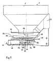
- the centrifugal spreader shown in the drawing has a fertilizer hopper 1 which extends with its longitudinal axis transversely to the direction of travel shown in FIG. 2 and has a width which corresponds to the total width permitted for road transport. It consists of a substantially rectangular upper part 2 and a lower part 3, the side walls 4, front wall 5 and rear wall 6 are inclined inwards. The front wall 5 and rear wall 6 run into a trough-shaped bottom (see FIG. 3). Appropriate attachments can optionally be placed on the open end face of the rectangular upper part 2 in order to increase the capacity of the storage container 1.
- Sieve frames 13 are inserted into the upper part 2 and a stiffening perforated plate is inserted in the middle.
- the centrifugal broadcaster also has a support frame 7 which essentially connects two vertical L-shaped supports 8 (FIG. 3) and one of their lower legs the crossbar 10 is made, the latter projects beyond the legs.
- the L-shaped supports 8 of the frame 7 are arranged within the front vertical alignment of the container 1.
- the container 1 can be drawn inwards in the region of its upper part 2 on the front wall 5.
- the greater part of the L-shaped support 8 is below the inclined front wall 5 of the container 1.
- the connection points 14 for the upper link and the connection points 15 for the lower link are as close as possible to the central longitudinal plane of the container, which results in a favorable center of gravity .
- a transverse conveyor 16 is arranged within the container 1 directly in the trough-shaped bottom. In the exemplary embodiment shown, it consists of a continuous shaft 17 and a screw spiral 18 carried at a distance from it.
- the cross conveyor 16 is driven on one side by means of a hydraulic motor 19 via a chain wheel 20 and is supported at 21 on the container in its central region.
- the trough-shaped bottom has flat sections 22 in the region of its outer ends (see FIG. 3), in which the discharge openings are provided. In the area of these discharge openings 24, the cross conveyor has no conveying elements, but only circulating elements which ensure that the material lying above the discharge opening is no longer conveyed to the outside, but is only circulated.
- centrifugal disc 25, 26 is arranged below each of the two outer discharge openings, the axis 27, 28 of which is offset from the discharge opening, so that the fertilizer leaving the discharge opening strikes the centrifugal discs 25, 26 at a distance from the axis.
- centrifugal disks 25, 26 have a number of centrifugal blades 29 in a conventional manner. Otherwise, the centrifugal disks 25, 26 are seated on swivel arms 30 which are mounted on vertical axes 31. In the exemplary embodiment according to FIG. 1, one centrifugal disc 25 can be pivoted forwards in the direction of travel 2, and the other centrifugal disc 26 can be pivoted backwards counter to the direction of travel, but preferably both centrifugal discs can only be pivoted backwards, as indicated in FIG. 2 for the centrifugal disc 25 shown on the right .
- the centrifugal disks 25, 26 are each driven by a hydraulic motor 32, each of which is attached to the outer end of the swivel arms 30.
- the centrifugal disks sit directly on the upward-pointing output shaft of the hydraulic motor 32 and are supplied by a pump (not shown) via the hydraulic lines 35, 36.
- the hydraulic lines 35, 36 are preferably laid protected in the swivel arms 30.
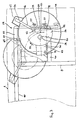
- the centrifugal disc 26 is shown with solid lines in the operating position and with dash-dotted lines in the pivoted-out position - similar to the illustration in FIG. 2 - for taking a scattering sample.
- the outlet opening 24 is indicated, which opens offset next to the axis of rotation 27 of the centrifugal disk 26.
- An adjusting lever 12 is mounted on the swivel arm 30, by means of which the centrifugal disc 26 can be swiveled out of the operating position into the position that releases the outlet opening 24.
- the swivel arm 30 and thus the slinger 26 is locked at the stop 11.
- the centrifugal disc can also be moved to a stop in the disengaged position be locked, as is indicated by dash-dotted lines.
- Figure 3 also shows the lower legs 9 of the L-shaped carrier 8 (Figure 1) of the support frame, which are connected at their rear free ends by the crossbar 10.
- the crossbeam 10 has a section 37 which projects outwardly beyond the lower leg 9 and forms part of a protective frame 38 which is formed by a further leg 39 extending in the direction of travel and a leg 40 parallel to the section 37 and by the lower leg 9 of FIG L-shaped support is completed.
- the swivel arm 30 is arranged and pivotable within the protective frame 38.
- the vertical pivot bearing 31 is seated on the leg 40 of the protective frame 38.
- FIG. 4 shows the hydraulic motor 32 driving the centrifugal disc 26, on the output shaft of which the centrifugal disc 26 is placed.
- the hydraulic motor 32 and thus also the outer end of the swivel arm 30 is protected at the bottom by a deflector blade 42 which is formed by a flat U-profile and which engages under the hydraulic motor 32 not only from below but also from the side.
- the deflector blade 42 is seated on two parallel levers 43 which are pivotably mounted on an axis 44 lying approximately in the direction of travel.
- the pivot axis 44 is formed, for example, by two bolts, one of which is arranged on the outer section 37 of the crossbar 10, the other on the parallel leg 40 of the protective frame 38 (see FIG. 3).
- a spring 45 which is attached to the protective frame 38 at 46, acts on the lever 43, the attachment point 46 being located approximately above the pivot axis 44. In this way, the deflector skid 42 is in the functional position (FIG. 4, right) held. In order to be able to pivot the deflector blade inwards from this position, a handle 47 is attached to its end.
- the spring 45 runs over the pivot axis 44 into the position shown on the left, in which it holds the deflector blade 42 in its pivoted position. In this position, the swivel arm 30 with the centrifugal disc 26 can be pivoted into the position shown in dash-dotted lines in FIG. 3, so that the space below the outlet opening 24 is free and the fertilizer jet emerges unhindered downward, and furthermore a collecting vessel is set up or suspended below the outlet opening 24 can be.
- the hydraulic motor 32 does not protrude below the lower edge of the protective frame 38.
- the deflector blade 42 lies approximately at the level of the lower edge of the protective frame 38 or higher.
- a protective ring 48 which is concentric with the centrifugal disc 26 is also attached to the swivel arm 30.
- An equally large protective ring 49 in a likewise concentric arrangement with the centrifugal disk 26 is mounted directly above the centrifuge disk on the storage container, so that effective accident protection against touching the centrifugal disk 26 is formed.
- FIG 3 an operating position of the centrifugal disc 26 is shown.
- the drop point is located below the outlet opening indicated by 24 near the axis 27 or the center of the disk 26.
- the centrifugal disk 26 can be pivoted continuously by means of the swivel arm 30, so that the drop point is approximately on the broken line 50 on the disk opposite to the Direction of rotation 51 and at the same time migrates to the outside.
- To adjust the drop point is the To Strike 11 formed as a locking pin, which is encompassed by a bolt 52 with a U-shaped cross section.
- the bolt 52 sits on one arm of the two-armed actuating lever 12, which is mounted at 53 on the swivel arm 30 and is provided with a handle 54 on its other arm.
- the locking pin 11 is seated on a plate 55 which is infinitely adjustable on the side rail 39 of the protective frame 38.
- a plate 55 which is infinitely adjustable on the side rail 39 of the protective frame 38.
- two aligned elongated holes 56 are arranged in the side rail 39, in which the guide plate 55 is guided by means of bolts.
- the bolts continue to cooperate with manually operated clamping nuts or are in turn designed as clamping screws which are provided with large-area rotary handles 57 or toggles.
- a millimeter-precise adjustment of the guide plate 55 or the locking pin 11 is possible by means of the adjusting spindle 58 with a turning handle 59.
- the set or to be set operating position can be read from a scale 60 arranged on the frame leg 39, which runs along an elongated hole, which in turn is engaged by an indicator 61 on the guide plate 55.
- the setting lever 12 is pivoted about the vertical bearing 53 by means of the handle 54.
- the operator can be supported by hand on the bracket 62 on the protective ring 48.
- the locking is opened against the force of the tension spring 63, which is stretched between the swivel arm 30 and the end of the two-armed actuating lever 12 opposite the handle 54 and which holds the bolt 52 in the operating position on the locking pin 11.
- the actuating lever 12 is actuated, the bolt 52 is released from the bolt pin 11.
- the swivel arm 30 can be counter-dashed Level position of the centrifugal disc can be pivoted.
- the guide plate 55 with the locking pin 11 can then be moved into the desired new operating position by means of the spindle 58.
- the centrifugal disc is pivoted back with the swivel arm and the bolt 52 is pushed over the bolt pin 11 again.
- the centrifugal disc 26 can be pivoted into the release position shown in dash-dot lines, for example in order to make a spreading test or to replace the centrifugal disc for a boundary spreading disc, for example.
- the adjusting lever 12 interacts with a fixed locking pin 64 on the rear frame leg 37.
- the adjusting lever 12 is provided at the end opposite the handle 54 with a hook-like bolt 65, which is arranged outside in the embodiment shown, which has the advantage that both locking pins 11 and 64 can be arranged on the frame legs on the inside.
- Moving the drop point along line 50 also changes the working width.
- the speed of the centrifugal disc 26 is adjusted accordingly by means of the hydraulic motor 32.
- the working width can also be varied by simultaneously moving the feed point and changing the speed of the discs.
Landscapes
- Life Sciences & Earth Sciences (AREA)
- Soil Sciences (AREA)
- Environmental Sciences (AREA)
- Fertilizing (AREA)
Applications Claiming Priority (2)
| Application Number | Priority Date | Filing Date | Title |
|---|---|---|---|
| DE3906757 | 1989-03-03 | ||
| DE3906757A DE3906757A1 (de) | 1989-03-03 | 1989-03-03 | Schleuderstreuer fuer duenger |
Publications (3)
| Publication Number | Publication Date |
|---|---|
| EP0385236A2 true EP0385236A2 (fr) | 1990-09-05 |
| EP0385236A3 EP0385236A3 (en) | 1990-11-28 |
| EP0385236B1 EP0385236B1 (fr) | 1994-10-05 |
Family
ID=6375412
Family Applications (1)
| Application Number | Title | Priority Date | Filing Date |
|---|---|---|---|
| EP90103231A Expired - Lifetime EP0385236B1 (fr) | 1989-03-03 | 1990-02-20 | Epandeur d'engrais à projection centrifuge |
Country Status (2)
| Country | Link |
|---|---|
| EP (1) | EP0385236B1 (fr) |
| DE (2) | DE3906757A1 (fr) |
Cited By (7)
| Publication number | Priority date | Publication date | Assignee | Title |
|---|---|---|---|---|
| FR2669806A1 (fr) * | 1990-12-04 | 1992-06-05 | Sulky Burel Sa | Procede et dispositif pour modifier le spectre d'une machine d'epandage centrifuge de produits en grains, en vue de l'epandage en bordure de champ. |
| EP0496285A1 (fr) * | 1991-01-22 | 1992-07-29 | Rauch Landmaschinenfabrik Gmbh | Epandeur centrifuge |
| FR2768014A1 (fr) | 1997-09-11 | 1999-03-12 | Rauch Landmaschfab Gmbh | Epandeur a deux disques a cadre de protection |
| FR2768013A1 (fr) | 1997-09-11 | 1999-03-12 | Rauch Landmaschfab Gmbh | Epandeur a deux disques commandes separement et a traverse inferieure mobile sur son support |
| EP0901748A1 (fr) * | 1997-08-16 | 1999-03-17 | Amazonen-Werke H. Dreyer GmbH & Co. KG | Méthode d'utilisation d'un distributeur centrifuge |
| FR2772550A1 (fr) | 1997-12-18 | 1999-06-25 | Rauch Landmaschfab Gmbh | Procede de distribution d'engrais en bordure de champ a l'aide de disques d'epandage |
| EP3771320B1 (fr) | 2019-07-30 | 2022-11-30 | Amazonen-Werke H. Dreyer SE & Co. KG | Procédé de réglage de l'inclinaison sur un appareil d'épandage agricole |
Families Citing this family (2)
| Publication number | Priority date | Publication date | Assignee | Title |
|---|---|---|---|---|
| DE102007013185A1 (de) * | 2007-03-20 | 2008-09-25 | Lehner Agrar Gmbh | Streuanordnung |
| DE102023115653A1 (de) * | 2023-06-15 | 2024-12-19 | Horsch Leeb Application Systems Gmbh | Behälter für ein landwirtschaftliches gut mit einer fördereinrichtung, landwirtschaftliches arbeitsgerät mit einem behälter und verfahren zum betrieb eines landwirtschaftlichen arbeitsgeräts |
Family Cites Families (11)
| Publication number | Priority date | Publication date | Assignee | Title |
|---|---|---|---|---|
| NL139440B (nl) * | 1963-05-07 | 1973-08-15 | Patent Concern Nv | Inrichting voor het spreiden van materiaal. |
| DE2031557A1 (de) * | 1970-06-26 | 1971-12-30 | Fahrzeug- Und Landmaschinenfabrik Sebastian Unsinn, 8890 Aichach | Vorrichtung zum Streuen von körnigem Streugut |
| DE2835011C2 (de) * | 1978-08-10 | 1980-10-02 | Amazonen-Werke H. Dreyer Gmbh & Co Kg, 4507 Hasbergen | Schleuderstreuer, insbesondere für gekörnte Düngemittel |
| DE3214769A1 (de) * | 1982-04-21 | 1983-10-27 | Ernst 7326 Heiningen Weichel | Landwirtschaftliches streufahrzeug |
| GB2120914B (en) * | 1982-05-17 | 1985-10-02 | Transport Engineering Limited | Granular material spreader |
| DE3427367C2 (de) * | 1984-07-25 | 1986-08-21 | Max Pietsch KG GmbH & Co, 3014 Laatzen | Einrichtung für ein Streufahrzeug |
| DE8502091U1 (de) * | 1985-01-26 | 1985-05-09 | Epoke Süd Alfred Thomsen GmbH & Co KG, 6405 Eichenzell | Anbaustreugeraet |
| DE3502569C2 (de) * | 1985-01-26 | 1995-07-13 | Epoke Maschinenbau Alfred Thom | Anbaustreugerät |
| EP0192089B1 (fr) * | 1985-02-06 | 1991-08-28 | Amazonen-Werke H. Dreyer GmbH & Co. KG | Distributeur à disques, spécialement pour engrais en granulés |
| WO1988009609A2 (fr) * | 1987-06-04 | 1988-12-15 | Rauch Landmaschinenfabrik Gmbh | Repandeur centrifuge d'engrais |
| DE8807900U1 (de) * | 1988-06-18 | 1988-10-20 | Kuxmann, Ursula, 4800 Bielefeld | Schleuderstreuer |
-
1989
- 1989-03-03 DE DE3906757A patent/DE3906757A1/de not_active Withdrawn
-
1990
- 1990-02-20 EP EP90103231A patent/EP0385236B1/fr not_active Expired - Lifetime
- 1990-02-20 DE DE59007365T patent/DE59007365D1/de not_active Expired - Fee Related
Cited By (9)
| Publication number | Priority date | Publication date | Assignee | Title |
|---|---|---|---|---|
| FR2669806A1 (fr) * | 1990-12-04 | 1992-06-05 | Sulky Burel Sa | Procede et dispositif pour modifier le spectre d'une machine d'epandage centrifuge de produits en grains, en vue de l'epandage en bordure de champ. |
| EP0489674A1 (fr) * | 1990-12-04 | 1992-06-10 | Sulky-Burel S.A. | Procédé et dispositif pour modifier le spectre d'une machine d'épandage centrifuge de produits en grains, en vue de l'épandage en bordure de champ |
| EP0496285A1 (fr) * | 1991-01-22 | 1992-07-29 | Rauch Landmaschinenfabrik Gmbh | Epandeur centrifuge |
| EP0901748A1 (fr) * | 1997-08-16 | 1999-03-17 | Amazonen-Werke H. Dreyer GmbH & Co. KG | Méthode d'utilisation d'un distributeur centrifuge |
| FR2768014A1 (fr) | 1997-09-11 | 1999-03-12 | Rauch Landmaschfab Gmbh | Epandeur a deux disques a cadre de protection |
| FR2768013A1 (fr) | 1997-09-11 | 1999-03-12 | Rauch Landmaschfab Gmbh | Epandeur a deux disques commandes separement et a traverse inferieure mobile sur son support |
| FR2772550A1 (fr) | 1997-12-18 | 1999-06-25 | Rauch Landmaschfab Gmbh | Procede de distribution d'engrais en bordure de champ a l'aide de disques d'epandage |
| DE19856926C2 (de) * | 1997-12-18 | 2003-06-18 | Rauch Landmaschfab Gmbh | Verfahren zum Verteilen von Streugut, insbesondere Düngemitteln |
| EP3771320B1 (fr) | 2019-07-30 | 2022-11-30 | Amazonen-Werke H. Dreyer SE & Co. KG | Procédé de réglage de l'inclinaison sur un appareil d'épandage agricole |
Also Published As
| Publication number | Publication date |
|---|---|
| DE59007365D1 (de) | 1994-11-10 |
| EP0385236A3 (en) | 1990-11-28 |
| DE3906757A1 (de) | 1990-09-06 |
| EP0385236B1 (fr) | 1994-10-05 |
Similar Documents
| Publication | Publication Date | Title |
|---|---|---|
| DE3529452A1 (de) | Streugeraet | |
| CH641318A5 (de) | Streugeraet fuer koerniges und/oder pulveriges gut. | |
| EP0385236B1 (fr) | Epandeur d'engrais à projection centrifuge | |
| DE2913738A1 (de) | Verfahren zur veraenderung der streuarbeit von schleuderstreuern | |
| EP0410312B1 (fr) | Distributeur centrifuge de matériaux granulaires, notamment d'engrais | |
| EP0545894B2 (fr) | Epandeur centrifuge | |
| DE3442465C2 (de) | Streugerät, insbesondere Mineraldungstreuer | |
| EP0427936B1 (fr) | Epandeur d'engrais centrifuge | |
| DE2044566C3 (de) | Streugerät | |
| WO1988009609A2 (fr) | Repandeur centrifuge d'engrais | |
| DE69107033T2 (de) | Verfahren und Vorrichtung zum Modifizieren des Spektrums eines Schleuderstreuers für körniges Material, um das Streuen auf den Feldrand zu ermöglichen. | |
| DE2010863C3 (de) | Streugerät | |
| EP0559242A2 (fr) | Expandeur centrifuge | |
| DE2701156A1 (de) | Streugeraet, insbesondere mineralduengerstreuer | |
| DE19946851A1 (de) | Düngerstreuer | |
| DE2917807A1 (de) | Streugeraet fuer koerniges und/oder pulveriges gut | |
| DE2461762A1 (de) | Maschine zum ausbringen von saatgut und duengemitteln | |
| DE3405245A1 (de) | Streugeraet fuer koerniges und/oder pulveriges streugut | |
| DE1924631C3 (de) | Streugerät | |
| DE2628798A1 (de) | Anbauvorrichtung fuer schleuderduengerstreuer | |
| DE2344346C3 (de) | Streumaschine | |
| DE1943012A1 (de) | Vorrichtung zum Ausbringen von gekoerntem oder pulverfoermigem Material ueber kleinere Parzellen | |
| EP0376013A2 (fr) | Epandeur centrifuge pour engrais | |
| DE3335806C2 (de) | Vorrichtung zum Streuen von schüttfähigem Gut | |
| DE3911583A1 (de) | Schleuderduengerstreuer |
Legal Events
| Date | Code | Title | Description |
|---|---|---|---|
| PUAI | Public reference made under article 153(3) epc to a published international application that has entered the european phase |
Free format text: ORIGINAL CODE: 0009012 |
|
| AK | Designated contracting states |
Kind code of ref document: A2 Designated state(s): DE FR GB |
|
| PUAL | Search report despatched |
Free format text: ORIGINAL CODE: 0009013 |
|
| AK | Designated contracting states |
Kind code of ref document: A3 Designated state(s): DE FR GB |
|
| 17P | Request for examination filed |
Effective date: 19901221 |
|
| 17Q | First examination report despatched |
Effective date: 19920320 |
|
| GRAA | (expected) grant |
Free format text: ORIGINAL CODE: 0009210 |
|
| AK | Designated contracting states |
Kind code of ref document: B1 Designated state(s): DE FR GB |
|
| PG25 | Lapsed in a contracting state [announced via postgrant information from national office to epo] |
Ref country code: GB Effective date: 19941005 |
|
| REF | Corresponds to: |
Ref document number: 59007365 Country of ref document: DE Date of ref document: 19941110 |
|
| ET | Fr: translation filed | ||
| GBV | Gb: ep patent (uk) treated as always having been void in accordance with gb section 77(7)/1977 [no translation filed] |
Effective date: 19941005 |
|
| PLBE | No opposition filed within time limit |
Free format text: ORIGINAL CODE: 0009261 |
|
| STAA | Information on the status of an ep patent application or granted ep patent |
Free format text: STATUS: NO OPPOSITION FILED WITHIN TIME LIMIT |
|
| 26N | No opposition filed | ||
| PGFP | Annual fee paid to national office [announced via postgrant information from national office to epo] |
Ref country code: DE Payment date: 20000225 Year of fee payment: 11 |
|
| PGFP | Annual fee paid to national office [announced via postgrant information from national office to epo] |
Ref country code: FR Payment date: 20000229 Year of fee payment: 11 |
|
| PG25 | Lapsed in a contracting state [announced via postgrant information from national office to epo] |
Ref country code: FR Free format text: LAPSE BECAUSE OF NON-PAYMENT OF DUE FEES Effective date: 20011031 |
|
| REG | Reference to a national code |
Ref country code: FR Ref legal event code: ST |
|
| PG25 | Lapsed in a contracting state [announced via postgrant information from national office to epo] |
Ref country code: DE Free format text: LAPSE BECAUSE OF NON-PAYMENT OF DUE FEES Effective date: 20011201 |