EP0385261A1 - Installation de transport ou de montage actionnable manuellement et flexible pour palettes - Google Patents
Installation de transport ou de montage actionnable manuellement et flexible pour palettes Download PDFInfo
- Publication number
- EP0385261A1 EP0385261A1 EP90103397A EP90103397A EP0385261A1 EP 0385261 A1 EP0385261 A1 EP 0385261A1 EP 90103397 A EP90103397 A EP 90103397A EP 90103397 A EP90103397 A EP 90103397A EP 0385261 A1 EP0385261 A1 EP 0385261A1
- Authority
- EP
- European Patent Office
- Prior art keywords
- pallet
- pallets
- work table
- flexible transport
- assembly device
- Prior art date
- Legal status (The legal status is an assumption and is not a legal conclusion. Google has not performed a legal analysis and makes no representation as to the accuracy of the status listed.)
- Withdrawn
Links
- 238000009434 installation Methods 0.000 title abstract description 4
- 238000012546 transfer Methods 0.000 claims abstract description 53
- 238000005096 rolling process Methods 0.000 claims abstract description 28
- 238000006073 displacement reaction Methods 0.000 claims abstract description 10
- 238000010276 construction Methods 0.000 claims description 6
- 238000009826 distribution Methods 0.000 claims description 4
- 230000036316 preload Effects 0.000 claims description 4
- 239000002023 wood Substances 0.000 claims description 4
- 239000002131 composite material Substances 0.000 claims description 3
- 229910000831 Steel Inorganic materials 0.000 claims description 2
- 230000009471 action Effects 0.000 claims description 2
- 238000007667 floating Methods 0.000 claims description 2
- 239000000463 material Substances 0.000 claims description 2
- 239000010959 steel Substances 0.000 claims description 2
- 239000011248 coating agent Substances 0.000 claims 1
- 238000000576 coating method Methods 0.000 claims 1
- 238000012545 processing Methods 0.000 description 15
- 230000008901 benefit Effects 0.000 description 4
- 238000000034 method Methods 0.000 description 4
- 230000008569 process Effects 0.000 description 4
- 239000000969 carrier Substances 0.000 description 3
- 239000002184 metal Substances 0.000 description 2
- 239000011120 plywood Substances 0.000 description 2
- 238000002360 preparation method Methods 0.000 description 2
- 238000007792 addition Methods 0.000 description 1
- 230000003139 buffering effect Effects 0.000 description 1
- 230000008859 change Effects 0.000 description 1
- 238000006243 chemical reaction Methods 0.000 description 1
- 230000008878 coupling Effects 0.000 description 1
- 238000010168 coupling process Methods 0.000 description 1
- 238000005859 coupling reaction Methods 0.000 description 1
- 238000011161 development Methods 0.000 description 1
- 230000018109 developmental process Effects 0.000 description 1
- 230000000694 effects Effects 0.000 description 1
- 238000002474 experimental method Methods 0.000 description 1
- 239000000945 filler Substances 0.000 description 1
- 238000003780 insertion Methods 0.000 description 1
- 230000037431 insertion Effects 0.000 description 1
- 229910001338 liquidmetal Inorganic materials 0.000 description 1
- 238000003754 machining Methods 0.000 description 1
- 238000004519 manufacturing process Methods 0.000 description 1
- 230000007246 mechanism Effects 0.000 description 1
- 238000005555 metalworking Methods 0.000 description 1
- BNHGKKNINBGEQL-UHFFFAOYSA-M sodium;5-ethyl-5-(3-methylbutyl)pyrimidin-3-ide-2,4,6-trione Chemical compound [Na+].CC(C)CCC1(CC)C(=O)NC(=O)[N-]C1=O BNHGKKNINBGEQL-UHFFFAOYSA-M 0.000 description 1
- 239000000725 suspension Substances 0.000 description 1
Images


Classifications
-
- B—PERFORMING OPERATIONS; TRANSPORTING
- B23—MACHINE TOOLS; METAL-WORKING NOT OTHERWISE PROVIDED FOR
- B23Q—DETAILS, COMPONENTS, OR ACCESSORIES FOR MACHINE TOOLS, e.g. ARRANGEMENTS FOR COPYING OR CONTROLLING; MACHINE TOOLS IN GENERAL CHARACTERISED BY THE CONSTRUCTION OF PARTICULAR DETAILS OR COMPONENTS; COMBINATIONS OR ASSOCIATIONS OF METAL-WORKING MACHINES, NOT DIRECTED TO A PARTICULAR RESULT
- B23Q7/00—Arrangements for handling work specially combined with or arranged in, or specially adapted for use in connection with, machine tools, e.g. for conveying, loading, positioning, discharging, sorting
- B23Q7/14—Arrangements for handling work specially combined with or arranged in, or specially adapted for use in connection with, machine tools, e.g. for conveying, loading, positioning, discharging, sorting co-ordinated in production lines
- B23Q7/1426—Arrangements for handling work specially combined with or arranged in, or specially adapted for use in connection with, machine tools, e.g. for conveying, loading, positioning, discharging, sorting co-ordinated in production lines with work holders not rigidly fixed to the transport devices
Definitions
- the invention relates to a manually operable flexible transport or assembly device for pallets (to be machined) carrying workpieces for device construction, for feeding loaded pallets to machine tables and the like. Like. According to the preamble of claim 1.
- the need to bring the sometimes heavy pallets on the machine tool work table into a centered fixed position can be problematic so that the machining process can then take place fully automatically, for example, in a numerically controlled workflow.
- a lengthy moving and moving of the pallet when transferring it from the movable carriage or trolley to the work table may be necessary until the pallet is finally seated with millimeter accuracy and the centering work can be completed.
- the invention is therefore based on the object to solve a problem so far neglected in the field of pallet transport by relatively simple means that a flexible transport or for manual transport or for the movement of carrier plates or pallets caused solely by human labor Installation device is created, which is simple, can be easily adapted to machine tools with different table heights and both a simple manual transfer of the pallets and the final one Direction and adjustment of such a pallet, for example, on the work table of an associated machine tool or processing machine without major difficulties.
- the invention solves this problem with the characterizing features of the main claim and has the advantage that basically just as quickly and effortlessly as with automatic transport systems, the z. B. are not always usable because of different table heights, the pallet exchange as well as the bringing up and taking away of the pallets to and from the machine tools is possible, the fact that the invention is a problem-free manual shifting of the pallets, for example, from one in front of each is a further advantage
- Machine tool arranged pallet buffer table allows to the work table of the machine tool. This work can be carried out by an operator with little effort and without the use of excessive force because the pallets on the pallet buffer table, on a transfer bridge and on the work table of the machine tool are carried by special support means, i.e. they are not directly on the documents mentioned.
- the support means can be a plurality of ball rolling elements, which are embedded in the pallet buffer table and in the work table of the machine tool, so that the underside of each is completed, usually very much, by their respective workpiece structure heavy pallet is only touched by the individual spherical elements. This makes it easy to move the individual pallets by hand even from a standstill because there is hardly any friction and therefore a single operator can move each pallet in any direction.
- a further preferred embodiment of the support means consists in that they form or consist of an air layer, even if it is only very thin, so that the underside of the pallet cannot come into direct contact with the top sides of the pallet buffer table or work table of the machine tool.
- Such a very thin, air-bearing layer supporting the pallet can be produced by a suitably designed compressed air supply, so that, similar to the case with the known air boats, the pallets, however, only lift off slightly from the base and then, of course, because there is no friction more is available, can also be easily moved by hand in any direction. The operator only needs to overcome the inertial mass of the pallets.
- each pallet on its underside with outlet openings for supplied compressed air that are distributed in corresponding patterns, so that the pallet stands out from any then understandably smooth surface and hovers over it as long as the compressed air is supplied.
- outlet openings for supplied compressed air that are distributed in corresponding patterns, so that the pallet stands out from any then understandably smooth surface and hovers over it as long as the compressed air is supplied.
- a pallet can rise up to several tenths of a millimeter soaring over the table surface.
- the invention is particularly suitable both for the transport of pallets to and from processing machines, for example NC machines, that is to say for loading the processing machines or for completing set-up stations if these are arranged elsewhere.
- processing machines for example NC machines
- several set-up stations each consisting of a single pallet table, can be connected to a common plate buffer table via the corresponding transfer bridge connections, which in turn is then connected to other locations or set-up stations via further transfer bridges or directly to the tables of processing machines.
- each machine tool has the same height as the respective machine tool table to bring or pick up pallets from any external pallet transport system.
- This can be a forklift or another mobile trolley, in which, as with a forklift, different lifting heights can be set, so that pallets processed from the different heights of the pallet buffer tables can be removed and fresh pallets can be put on, for example from the setup station transfer system. where other heights are allowed.
- the pallet can be properly and securely seated in the processing position by moving the pallet on the machine tool table after it has been finally adjusted and centered Pallet can be screwed down to the table, so to speak, in the case of individual load-bearing ball rolling elements, these are pushed away resiliently until the pallet itself rests on the work table in the normal position or, in the case of compressed air support, its supply is switched off, so that the pallet is in the desired end position the work table can first be adjusted with high precision with compressed air support and then screwed on.
- Such a flexible transport and assembly system for pallets is suitable for any machine tool passable, can be set up inexpensively and without problems and, if desired, can also be cleared away and enables the pallet to be changed at least at the same speed as is also possible with standardized systems with automated pallet transport trolleys, but does not have their disadvantageous limitations, i.e. the requirement always same working table heights.
- the invention therefore has the following advantages.
- - The result is a simple, inexpensive and technically problem-free system for solving logistical provision problems on machine tools;
- - The invention enables longitudinal conveying, cross conveying, corner transfer or buffering and the easy adjustment of pallets on the machine table;
- - The material flow is rationalized, workpieces can be made available and picked up without wasting time;
- - The transfer location is independent of different machine table heights; - Structural changes in the respective production halls are not necessary, since the installation is possible even in the smallest space and can be expanded as required;
- the set-up or set-up times on the machine are significantly reduced per device change, whereby -
- the system is suitable for machines with and without a pallet changer.
- the border as a lateral guide and securing ensures that the pallet from the respective table - usually it will be the pallet pouf finished or even separate set-up tables, cannot slip, but on the other hand reliable sliding is possible in the desired direction of movement.
- the inside of the lateral guide webs can be equipped with ball bearings, so that tilting or jamming is reliably prevented.
- the previously known, largely automated pallet transport and transfer systems are dispensed with, which cannot be used in all cases, and a transfer system is created which, with a particularly simple and inexpensive structure, simplifies the logistical process of work preparation via a separate one Setup up to the loading of the processing machine is mastered, whereby even the heaviest workpieces can be manually centered and brought to a desired fixed position.
- a work table is assigned to each pallet buffer table via a transfer bridge - the work table can be a machine work table or a set-up table, whereby any additions in any direction are possible, in each case via corresponding transfer bridges.
- the transfer bridges consist of spars which are fastened to the pallet buffer table and to the respective work table, but can be implemented as desired, two spars each forming a transfer bridge and equipped with ball bearings to ensure that manual displacement is also possible without problems via the transfer bridges .
- a corresponding transfer is also possible on the basis of the same elements in the case of set-up stations set up elsewhere, which then each consist of separate workbench tables that form the set-up stations and which are connected to a pallet buffer table with a correspondingly desired number of pallet spaces via corresponding transfer bridges.
- the pallet transport and assembly system 10 shown in FIGS. 1, 2 and 3 comprises ball rolling elements as support means for the pallets lying or transported on the pallet buffer table or the set-up station work table or the machine tool work table - use the embodiments shown in FIGS. 4-6 compressed air lifting devices as support.
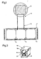
- the pallet transfer system 10 of FIG. 1 comprises a pallet buffer table 11 and a machine tool work table 12, these two parts being connected via a bridge construction, which is referred to below as transfer bridge 13, and consisting of two main spars or supports 13a and 13b.
- the pallet buffer table 11 can be of any construction and, as is customary with tables, comprises an extended worktop 11a which is supported on the floor of the machine hall by a larger number of table legs 12b. Care is taken, however, that this results in a table height for the pallet buffer table which corresponds to the work table height of the assigned machine tool or the assigned set-up work table, so that an operator transfers a pallet from one of these tables to the other via the transfer bridge 13 can push here without having to overcome a gradient that would be an obstacle to such transport or would make this impossible.
- the table length in the transverse direction in front of the machine tool is dimensioned such that there is space for three pallets, workpiece clamping tables or clamping plates , these three places in FIG. 1 being designated by reference numeral 14.
- the surface of the pallet buffer table where workpieces or pallets are placed on this clamping plate is equipped with any supporting elements that enable rolling friction when moving the pallets, which are known per se and of which a possible exemplary embodiment is shown in FIG. 13 and with 15 is designated.
- These support or support means which are referred to below as ball rolling elements and are effective between the respective table and transfer bridge surfaces and the lower surfaces of the pallets placed on them, are embedded in the surfaces of the two tables in such a way that the balls with their uppermost tip curvature decrease by a small predetermined amount, for example 1 mm, extend over the table surface.
- each ball rolling element is designed so that the support ball 15a (Fig. 3) is pressed upward with a comparatively strong spring force, for example disc springs 16 can be provided which press a cage part 17 upwards, which the support ball 15a over other small ones Intermediate balls 18 that also enable rolling friction in this area are supported.
- the ball rolling elements can each be designed as individual elements, i. H. that always a support ball 15a is mounted in a corresponding housing part, which is then, as indicated in Fig. 3 at 19, embedded in any distribution and pattern in the table surface.
- the ball rolling elements prefferably have the shape of a longitudinally extending one-piece bar, the bar having a predetermined length storing a larger number of individual support balls 15a in the usual spring-preloaded and slide-ball-supported version.
- the pallet buffer tables are preferably equipped with individual ball rolling elements, it is advisable to insert such longitudinal members, each with several ball rolling elements, into the T-slots that are present in each machine work table, as indicated in FIG. 3.
- a different type of rolling friction is provided for the transfer bridge 13;
- this consists of two supports 13a, 13b arranged at a predetermined distance from one another, approximately from the middle support of the pallet buffer table 11 to the machine tool work table and connected in a corresponding manner to both tables.
- Conventional ball bearings are provided here for the easy transfer of the pallets to the carriers 13a, 13b - these can also be stiffened to one another by any cross-members - which therefore each have an inner ring or an outer ring with a spherical ring in between.
- each ball bearing is then attached to the brackets 13a, 13b at a height such that the outer rings extend a slight distance above the support surface, rotating slightly in the direction of transport between the machine work table and the pallet buffer table, and ensuring that the pallets sliding off the tables slide onto the outer bearing rims of the transfer bridge and are then strictly conveyed by them only in the permissible direction of movement to the other table and are gradually taken over by the ball rolling elements assigned to them.
- All these pallet movements can be carried out by only one operator without great effort, a normal workflow being such that a fresh pallet is located on the pallet buffer table, for example in the right or left position, when the pallet on the machine tool table is accepted and is being processed .
- a normal workflow being such that a fresh pallet is located on the pallet buffer table, for example in the right or left position, when the pallet on the machine tool table is accepted and is being processed .
- the operator releases a fixing lock - this will be discussed further below - and the then freely movable, processed pallet is moved from the machine table to the transfer bridge and from there to the middle pallet buffer table position . From this position there is a further shift in the transverse direction to the one free space on the pallet buffer table, so that its middle position becomes free.
- the fresh pallet which is also on the pallet buffer table, is then shifted onto this, then by reversing the movement by 90 °, it reaches the machine work table via the transfer bridge. Once there, there is a highly precise alignment in the centering position, which is also possible with only one operator due to the effective rolling friction.
- the desired position for example, pallet centering holes are aligned with indexing holes on the machine table, fastening screws are inserted and the clamping plate or the pallet is screwed down on the machine table, whereby the previously outstanding support balls 15a are inserted into their resilient bearing be pressed, i.e. disappear from the worktop surface and the entire surface of the pallet rests securely on the machine table and is held by the fastening screws.
- a further preferred exemplary embodiment of the present invention which is shown in FIGS. 4-6, uses an air cushion between the adjoining surfaces as support means for the pallets lying on the pallet buffer table or on the work table and to be moved there, so that the underside of the pallet faces from the facing one Table surface is lifted and the pallet is, so to speak, if only a few tenths of a millimeter, floating.
- each pallet 20 has its own air guide and outlet system.
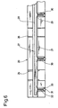
- 5 shows a pallet equipped in this way from the underside; One can see in the top view crisscross channels, which are closed again after the insertion, for example, of the compressed air transporting channels 21, air outlet points 22 being arranged along each channel at intervals, from which the compressed air 24 supplied to a suitable connection adapter 23 is arranged emerges again.
- the pallets Since the pallets have their own compressed air supply, but must be transportable, it is necessary in this case to connect the compressed air supply via a suitable longer and flexible hose connection, with corresponding connection couplings, so that the pallets can also be moved and transported.
- the type and structure of the air outlet openings 22 will be discussed in more detail below.
- FIG. 5 also shows a clamping plate preferred in the construction of the device as it is described in detail, for example, in German Patent 25 57 701 - wood core plates provided with metal surfaces can be used for the table surfaces are, in particular with steel sheet coated wood plywood, as they are known for example under the name Inmetal elements as composite elements and are described in a brochure of the same name from Blomberger Holzindustrie, 4933 Blomberg / Lippe.
- the second variant of the compressed air suspension system for pallets or clamping plates is that table surfaces facing the clamping plate are equipped with the appropriate air outlet openings in the desired distribution, which is also possible with appropriately designed machine work tables. It goes without saying that any mixed forms are also possible here;
- a pallet with its own air pressure supply system can be held on a smooth pallet buffer table or work table without air outlet openings by its own air pressure supply; it then slides over the ball bearing guides of the transfer bridge onto the work table, where either the ball rolling elements already explained above are located in the T-slots of the machine work table or on which the pallet itself uses its own air pressure lifting system.
- pallets or clamping plates without their own air pressure lifting system can be transported and moved on the table surfaces of the pallet buffer table or a set-up work table by means of a table-own air pressure lifting system; they always slide over the transfer bridge on their ball bearings and then either use their own air pressure lifting system in the area of the machine work table or slide again on the ball rolling elements already mentioned earlier.
- the pallet 20 shown there has, in addition to the fitting bores 25, which are positioned very precisely by insert bushings, as well as clamping bores 26 provided with an internal thread, a channel system 27, which consists of the longitudinal and transverse channels 21 already mentioned above, which, for example, open from the bottom into the Plate can be milled. Then, in the thus formed, initially still open channels for the distribution of air pressure, suitable hoses 28 are inserted, each opening at 29 in transverse bores 30 opening towards the underside of the pallet (or the table surface). The channels are then closed again by means of suitable hard or hardenable (plastic) fillers or liquid metal, in particular at the edge and upwards.
- suitable hard or hardenable (plastic) fillers or liquid metal in particular at the edge and upwards.
- valve balls 31 are seated, which are pressed under spring tension by a spring 32, so that the spherical surface of each valve ball is in contact with one of the Bore 30 formed seat 33 comes, which can be formed, for example, by a narrowing integral with the bore.
- the seat 33 is dimensioned such that the ball, with its outermost spherical round tip, projects somewhat beyond the flat surface (ie underside of the pallet or the surface of the table), so that then, when the corresponding pallet rests on the smooth surface of a table supporting it, the balls are pressed against their spring preload slightly lifted from their seat inwards into the bore 30, thereby forming, for example, a circular slot opening around the balls which the compressed air can then escape. If such an outlet opening is on the other hand opposite a bore or another depression, then the ball, also supported by the air pressure, presses onto its seat and seals this outlet point. It is understood that the valve mechanism described so far for the air outlet openings can also be used analogously on corresponding table surfaces with outlet openings for an air pressure lifting system.
- a further advantageous embodiment of the present invention which is suitable for all embodiments and can be used both on the pallet buffer table and on the machine work tables and set-up work table as well as on the transfer bridge, can be seen from the illustration in FIG. 4 and includes lateral ones Guides to secure the pallet position, which are particularly effective when the pallets on the tables, lifted by the air pressure lifting system or by the ball rolling elements, can be moved freely and with little effort in any direction.
- the lateral guides ensure that the pallets do not slip
- the guides preferably consisting of individual guide webs - transverse webs 35 and longitudinal webs 35 'can exist, which are placed on the table edges and have a strip-like shape.
- the guide webs 35, 35 ' have suitable bearing arrangements for ball bearings 36 so that their outer rings are directed inward beyond the webs onto the table, which they frame in each case. These ball bearings arranged on the inner sides of the guide webs ensure reliable sliding in the desired direction of movement when a pallet comes into contact with the ball bearing outer rings 36.
- the guide webs 35, 35 ' can be removed from the table surface edges so that, for example, a forklift or other device can put pallets on the table surface or remove them.
- the ends of the guide webs each have, in the exemplary embodiment shown, spherical handles 37 which end in pins which are pushed through aligned bores in the guide web ends and the associated table top.
Landscapes
- Engineering & Computer Science (AREA)
- Mechanical Engineering (AREA)
- Feeding Of Workpieces (AREA)
Applications Claiming Priority (4)
| Application Number | Priority Date | Filing Date | Title |
|---|---|---|---|
| DE3906423A DE3906423A1 (de) | 1989-03-01 | 1989-03-01 | Flexible transport- und montageeinrichtung fuer paletten bei werkzeugmaschinen |
| DE3906423 | 1989-03-01 | ||
| DE19904004160 DE4004160A1 (de) | 1989-03-01 | 1990-02-10 | Manuell betaetigbare flexible transport- oder montageeinrichtung fuer paletten |
| DE4004160 | 1990-02-10 |
Publications (1)
| Publication Number | Publication Date |
|---|---|
| EP0385261A1 true EP0385261A1 (fr) | 1990-09-05 |
Family
ID=25878314
Family Applications (1)
| Application Number | Title | Priority Date | Filing Date |
|---|---|---|---|
| EP90103397A Withdrawn EP0385261A1 (fr) | 1989-03-01 | 1990-02-22 | Installation de transport ou de montage actionnable manuellement et flexible pour palettes |
Country Status (2)
| Country | Link |
|---|---|
| EP (1) | EP0385261A1 (fr) |
| JP (1) | JPH02298454A (fr) |
Cited By (6)
| Publication number | Priority date | Publication date | Assignee | Title |
|---|---|---|---|---|
| EP0792719A1 (fr) * | 1996-03-01 | 1997-09-03 | Chiron-Werke GmbH & Co. KG | Centre d'usinage |
| GB2323068A (en) * | 1997-03-10 | 1998-09-16 | Moran Colin Christopher | Transfer of loads between work stations |
| EP3339223A1 (fr) | 2016-12-22 | 2018-06-27 | J. Michael Mehltretter | Poste de travail réglable ergonomique avec des billes |
| CN112852581A (zh) * | 2021-02-03 | 2021-05-28 | 广西民族师范学院 | 一种百香果全果制备果酒的方法 |
| CN113387115A (zh) * | 2021-06-19 | 2021-09-14 | 江西绿萌科技控股有限公司 | 一种输送线果杯振动减缓装置 |
| CN119017663A (zh) * | 2024-10-21 | 2024-11-26 | 浙江道远工贸有限公司 | 一种托盘生产设备及其生产工艺 |
Families Citing this family (4)
| Publication number | Priority date | Publication date | Assignee | Title |
|---|---|---|---|---|
| JP4969634B2 (ja) * | 2009-10-29 | 2012-07-04 | 株式会社牧野フライス製作所 | 工作機械の段取りステーション |
| CN115666844B (zh) * | 2020-05-20 | 2025-07-29 | Dmg森精机株式会社 | 托盘提供装置 |
| JP7765241B2 (ja) * | 2021-10-13 | 2025-11-06 | 株式会社鷺宮製作所 | 浮上装置およびその製造方法 |
| JP7449622B1 (ja) * | 2023-09-08 | 2024-03-14 | 株式会社鬨一精機 | 加工装置 |
Citations (4)
| Publication number | Priority date | Publication date | Assignee | Title |
|---|---|---|---|---|
| DE3241363A1 (de) * | 1981-11-20 | 1983-07-14 | Kearney & Trecker Corp., 53214 West Allis, Wis. | Anlage zum lagern und bearbeiten von teilen, insbesondere von metallteilen |
| DE3521285C1 (de) * | 1985-06-19 | 1986-09-04 | Werner und Kolb Werkzeugmaschinen GmbH, 1000 Berlin | Flexibles Fertigungssystem |
| US4715490A (en) * | 1985-04-26 | 1987-12-29 | Toshiba Kikai Kabushiki Kaisha | Automatic pallet changer |
| US4746258A (en) * | 1985-09-13 | 1988-05-24 | Litton Systems, Inc. | Floating table for article transport vehicle |
-
1990
- 1990-02-22 EP EP90103397A patent/EP0385261A1/fr not_active Withdrawn
- 1990-03-01 JP JP4736590A patent/JPH02298454A/ja active Pending
Patent Citations (4)
| Publication number | Priority date | Publication date | Assignee | Title |
|---|---|---|---|---|
| DE3241363A1 (de) * | 1981-11-20 | 1983-07-14 | Kearney & Trecker Corp., 53214 West Allis, Wis. | Anlage zum lagern und bearbeiten von teilen, insbesondere von metallteilen |
| US4715490A (en) * | 1985-04-26 | 1987-12-29 | Toshiba Kikai Kabushiki Kaisha | Automatic pallet changer |
| DE3521285C1 (de) * | 1985-06-19 | 1986-09-04 | Werner und Kolb Werkzeugmaschinen GmbH, 1000 Berlin | Flexibles Fertigungssystem |
| US4746258A (en) * | 1985-09-13 | 1988-05-24 | Litton Systems, Inc. | Floating table for article transport vehicle |
Cited By (10)
| Publication number | Priority date | Publication date | Assignee | Title |
|---|---|---|---|---|
| EP0792719A1 (fr) * | 1996-03-01 | 1997-09-03 | Chiron-Werke GmbH & Co. KG | Centre d'usinage |
| US5836064A (en) * | 1996-03-01 | 1998-11-17 | Chiron-Werke Gmbh & Co. Kg | Machining center |
| GB2323068A (en) * | 1997-03-10 | 1998-09-16 | Moran Colin Christopher | Transfer of loads between work stations |
| GB2323068B (en) * | 1997-03-10 | 2001-02-14 | Moran Colin Christopher | Manufacturing equipment and process |
| EP3339223A1 (fr) | 2016-12-22 | 2018-06-27 | J. Michael Mehltretter | Poste de travail réglable ergonomique avec des billes |
| DE102016125492A1 (de) | 2016-12-22 | 2018-06-28 | J. Michael Mehltretter | Ergonomisch einstellbarer Arbeitsplatz mit Kugeltisch |
| CN112852581A (zh) * | 2021-02-03 | 2021-05-28 | 广西民族师范学院 | 一种百香果全果制备果酒的方法 |
| CN112852581B (zh) * | 2021-02-03 | 2023-05-09 | 广西民族师范学院 | 一种百香果全果制备果酒的方法 |
| CN113387115A (zh) * | 2021-06-19 | 2021-09-14 | 江西绿萌科技控股有限公司 | 一种输送线果杯振动减缓装置 |
| CN119017663A (zh) * | 2024-10-21 | 2024-11-26 | 浙江道远工贸有限公司 | 一种托盘生产设备及其生产工艺 |
Also Published As
| Publication number | Publication date |
|---|---|
| JPH02298454A (ja) | 1990-12-10 |
Similar Documents
| Publication | Publication Date | Title |
|---|---|---|
| DE3832845C1 (en) | Assembly station having a positioning and holding apparatus | |
| DE4010024A1 (de) | Fertigungsanlage mit parallel- und nebenfoerderwegen | |
| EP0970900B1 (fr) | Dispositif et méthode de manutention mécanisé pour palettes | |
| DE102007005994B4 (de) | Puffereinrichtung | |
| DE2754095A1 (de) | Palettenwechsler in fertigungsanlagen | |
| DE3629069A1 (de) | Palettenzufuhreinrichtung fuer mindestens eine werkzeugmaschine | |
| DE4006486A1 (de) | Gehaeuseteil fuer eine arbeits- bzw. bearbeitungsstation einer fertigungsanlage | |
| DE3316050C2 (fr) | ||
| DE3241363A1 (de) | Anlage zum lagern und bearbeiten von teilen, insbesondere von metallteilen | |
| DE19607782C2 (de) | Maschinenzentrum | |
| DE2242475B2 (de) | Regallager mit in zwei Reihen angeordneten Regalen und einem dazwischen in einem Gang verfahrbaren Regalförderzeug | |
| DE60009200T2 (de) | Werkzeugmaschine zum Bearbeiten symmetrischer länglicher Elemente wie zu Beispiel Bauteilen für Stühle, Möbel oder andere solche Gegenstände | |
| DE3628760C2 (fr) | ||
| DE3115775A1 (de) | "vorrichtung zum uebernehmen, ausrichten und uebergeben einer palette o.dgl." | |
| DE3832865C1 (en) | Assembly station having a duplex conveyor | |
| DE3219459A1 (de) | Automatische foerderanlage zum transportieren von werkstuecken in einer maschinenwerkstatt | |
| DE4004160A1 (de) | Manuell betaetigbare flexible transport- oder montageeinrichtung fuer paletten | |
| EP1249409A1 (fr) | Dispositif de chargement avec des ventouses de préhension controlées | |
| DE10064523A1 (de) | Anlage zur Bearbeitung von Werkstücken | |
| EP0338132B1 (fr) | Table d'alignement | |
| DE3222224C2 (fr) | ||
| EP1924399B1 (fr) | Dispositif pour transporter des supports de piece a usiner | |
| DE19500400C2 (de) | Auflagersystem für mit Kunststoffolie zu überziehende plattenförmige Werkstücke | |
| DD200717A1 (de) | Einrichtung zum wechseln und speichern von werkstuecktraegern fuer bearbeitungsstationen | |
| DE1854784U (de) | Uebersetzungsvorrichtung fuer eine anlage zur herstellung von metallkonstruktionen. |
Legal Events
| Date | Code | Title | Description |
|---|---|---|---|
| PUAI | Public reference made under article 153(3) epc to a published international application that has entered the european phase |
Free format text: ORIGINAL CODE: 0009012 |
|
| AK | Designated contracting states |
Kind code of ref document: A1 Designated state(s): AT BE CH DE DK ES FR GB GR IT LI LU NL SE |
|
| 17P | Request for examination filed |
Effective date: 19901004 |
|
| 17Q | First examination report despatched |
Effective date: 19910705 |
|
| STAA | Information on the status of an ep patent application or granted ep patent |
Free format text: STATUS: THE APPLICATION IS DEEMED TO BE WITHDRAWN |
|
| 18D | Application deemed to be withdrawn |
Effective date: 19921007 |