EP0385355A1 - Endverbinder für einen Stabilisatorstab - Google Patents
Endverbinder für einen Stabilisatorstab Download PDFInfo
- Publication number
- EP0385355A1 EP0385355A1 EP90103708A EP90103708A EP0385355A1 EP 0385355 A1 EP0385355 A1 EP 0385355A1 EP 90103708 A EP90103708 A EP 90103708A EP 90103708 A EP90103708 A EP 90103708A EP 0385355 A1 EP0385355 A1 EP 0385355A1
- Authority
- EP
- European Patent Office
- Prior art keywords
- grommet
- washer
- subassembly
- grommets
- snap
- Prior art date
- Legal status (The legal status is an assumption and is not a legal conclusion. Google has not performed a legal analysis and makes no representation as to the accuracy of the status listed.)
- Withdrawn
Links
- 239000003381 stabilizer Substances 0.000 title claims abstract description 66
- 238000000034 method Methods 0.000 claims abstract description 18
- 239000000725 suspension Substances 0.000 claims abstract description 17
- 239000013536 elastomeric material Substances 0.000 claims abstract description 12
- 229910000831 Steel Inorganic materials 0.000 description 12
- 239000010959 steel Substances 0.000 description 12
- 229920003052 natural elastomer Polymers 0.000 description 4
- 229920001194 natural rubber Polymers 0.000 description 4
- 229920003051 synthetic elastomer Polymers 0.000 description 4
- 239000005061 synthetic rubber Substances 0.000 description 4
- 230000004323 axial length Effects 0.000 description 2
- 238000005219 brazing Methods 0.000 description 2
- 238000003466 welding Methods 0.000 description 2
- 230000000712 assembly Effects 0.000 description 1
- 238000000429 assembly Methods 0.000 description 1
- 239000000463 material Substances 0.000 description 1
- 239000002861 polymer material Substances 0.000 description 1
- 230000000087 stabilizing effect Effects 0.000 description 1
Images
Classifications
-
- B—PERFORMING OPERATIONS; TRANSPORTING
- B60—VEHICLES IN GENERAL
- B60G—VEHICLE SUSPENSION ARRANGEMENTS
- B60G21/00—Interconnection systems for two or more resiliently-suspended wheels, e.g. for stabilising a vehicle body with respect to acceleration, deceleration or centrifugal forces
- B60G21/02—Interconnection systems for two or more resiliently-suspended wheels, e.g. for stabilising a vehicle body with respect to acceleration, deceleration or centrifugal forces permanently interconnected
- B60G21/04—Interconnection systems for two or more resiliently-suspended wheels, e.g. for stabilising a vehicle body with respect to acceleration, deceleration or centrifugal forces permanently interconnected mechanically
- B60G21/05—Interconnection systems for two or more resiliently-suspended wheels, e.g. for stabilising a vehicle body with respect to acceleration, deceleration or centrifugal forces permanently interconnected mechanically between wheels on the same axle but on different sides of the vehicle, i.e. the left and right wheel suspensions being interconnected
- B60G21/055—Stabiliser bars
- B60G21/0551—Mounting means therefor
-
- B—PERFORMING OPERATIONS; TRANSPORTING
- B60—VEHICLES IN GENERAL
- B60G—VEHICLE SUSPENSION ARRANGEMENTS
- B60G2204/00—Indexing codes related to suspensions per se or to auxiliary parts
- B60G2204/10—Mounting of suspension elements
- B60G2204/12—Mounting of springs or dampers
- B60G2204/122—Mounting of torsion springs
- B60G2204/1224—End mounts of stabiliser on wheel suspension
-
- Y—GENERAL TAGGING OF NEW TECHNOLOGICAL DEVELOPMENTS; GENERAL TAGGING OF CROSS-SECTIONAL TECHNOLOGIES SPANNING OVER SEVERAL SECTIONS OF THE IPC; TECHNICAL SUBJECTS COVERED BY FORMER USPC CROSS-REFERENCE ART COLLECTIONS [XRACs] AND DIGESTS
- Y10—TECHNICAL SUBJECTS COVERED BY FORMER USPC
- Y10S—TECHNICAL SUBJECTS COVERED BY FORMER USPC CROSS-REFERENCE ART COLLECTIONS [XRACs] AND DIGESTS
- Y10S411/00—Expanded, threaded, driven, headed, tool-deformed, or locked-threaded fastener
- Y10S411/915—Bolt having packing joint
Definitions
- Such a link is connected to a stabilizer bar, which is formed with an aperture of a suitable diameter near one end, and to a control element, which also is formed with such an aperture, as the end link is assembled, by causing the tubular extensions of the first and second grommets to extend axially, from opposite directions, into one such aperture, as the bolt shank is extended through the first and second grommets, and causing the tubular extensions of the third and fourth grommets to extend axially, from opposite directions, into the other aperture, as the bolt shank is extended through the third and fourth grommets.
- the opposite ends of the grommets form tubular extensions, which are smaller in outer diameter than the snap-fittable ends of the grommets.
- the stabilizer bar is formed with a circular aperture near one end
- the control element also is formed with a circular aperture.
- Each of the apertures is smaller in diameter than the outer diameter of the grommets, except at the tubular extensions, which are adapted to fit axially into the apertures.
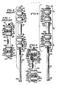
- FIGURES 1 and 2 Before a detailed description of an end link constituting a preferred embodiment of this invention is given, an end link 10 exemplifying prior art will be first described, as shown in FIGURES 1 and 2.
- the end link 10 is shown in FIGURE 1 as connected to a stabilizer bar 12, which has a circular aperture 14 near one end 16 of the stabilizer bar 12, and to a control element 18, such as a control arm or an axle housing bracket, which also is formed with a circular aperture 20, in a suspension system for a motor vehicle, such as an automobile or a light truck.
- a stabilizer bar 12 which has a circular aperture 14 near one end 16 of the stabilizer bar 12
- a control element 18 such as a control arm or an axle housing bracket
- the thickness of the stabilizer bar 12 at the margin of the aperture 14 and the thickness of the control element 18 at the margin of the aperture 20 are approximately equal.
- the end link 10 comprises a steel bolt 22, which has a head 24 and a shank 26 with a threaded end 28, a steel nut 30 therefor, a tubular steel sleeve 32, first, second, third, and fourth annular steel washers 34, 36, 38, and 40 respectively, and first, second, third and fourth annular grommets 42, 44, 46 and 48 respectively.
- Each of the grommets of the end link 10 is molded of an elastomeric material, such as a natural or synthetic rubber. Each conforms in shape to the other grommets of the end link 10 and has an annular body, which is chamfered at each end. Moreover, each has a larger end and a smaller end, which forms a tubular extension of the annular body of the grommet.
- the grommets 42, 44, 46, and 48 respectively have annular bodies 42 a , 44 a , 46 a , and 48 a respectively with tubular extensions 42 b , 44 b , 46 b , and 48 b respectively.
- the end link 10 is assembled by extending the bolt shank 26 successively through the first washer 34, the first grommet 42 and the second grommet 44, tne second washer 36, the sleeve 32, the third washer 38, the third grommet 46 and the fourth grommet 48, and the fourth washer 40, and threading the nut 30 onto the threaded end 28 of the bolt shank 26.
- the grommet 42, 44, 46, and 48 must be axially oriented such that the tubular extensions 42 b and 44 b face each other and such that the tubular extensions 46 b and 48 b face each other.
- Each of the apertures 14 and 20, as formed in the stabilizer bar 12 and the control element 18 respectively, has a diameter smaller than the outer diameter of the grommets 42, 44, 46, and 48, except at the tubular extensions 42 b , 44 b , 46 b and 48 b , which are adapted to fit axially into the apertures 14 and 20.
- Each of the tubular extensions 42 b , 44 b , 46 b , and 48 b has an axial length not greater than one-half of the thickness of the stabilizer bar 12 at the margin of the aperture 14 and not greater than one-half of the thickness of the control element 18 at the margin of the aperture 20.
- the end link 10 is connected to the stabilizer bar 12 and to the control element 18, as the end link 10 is assembled, by causing the tubular extension 42 b of the first grommet 42 and the tubular extension 44 b of the second grommet 44 to extend axially, from opposite directions, into the aperture 20 formed in the control element 18, as the bolt shank 26 is extended through the first grommet 42 and the second grommet 44, and causing the tubular extension 46 b of the third grommet 46 and the tubular extension 48 b of the fourth grommet 48 to extend axially, from opposite directions, into the aperture 14 formed in the stabilizer bar 12, as the bolt shank 26 is extended through the third grommet 46 and the fourth grommet 48.
- an end link 100 constituting a preferred embodiment of this invention comprises several subassemblies, which are pre-assembled, so as to facilitate assembly of the end link 100 and connection of the end link 100 to a stabilizer bar 102, which is like the stabilizer bar 12 and has a circular aperture 104 near one end 106 of the stabilizer bar 102, and to a control element 108, which is like the control element 18 and also is formed with a circular aperture 110.
- the stabilizer bar 102 and the control element 108 are used in a suspension system for a motor vehicle, such as an automobile or a light truck. Desirably, as shown, the thickness of the stabilizer bar 102 at the margin of the aperture 104 and the thickness of the control element 108 at the margin of the aperture 110 are approximately equal.
- the end link 100 comprises a steel bolt 112, which has a head 114 and a shank 116 with a threaded end 118, a steel nut 120 therefor, a unitary spool 122, which has a steel tubular body 124 with an annular steel flange 126 at its lower end and an annular steel flange 128 at its upper end, a first annular steel washer 130 and a second annular steel washer 132, and first, second, third, and fourth annular grommets 134, 136, 138, and 140 respectively.
- the annular grommets 134 and 136 are the lowermost and uppermost grommets respectively, and the annular grommets 138 and 140 are therebetween with the annular grommet 138 below the annular grommet 140.
- the tubular body 124 may be suitably formed from a flat piece of steel stock with an axial seam (not shown) and with the annular flanges 126 and 128, which have tubular extensions (see, e.g., the tubular extension 128 a of the annular flange 128, as shown in FIGURE 3) extending into the tubular body 124, being welded or brazed to its opposite ends.
- Each of the annular grommets 134, 136, 138, and 140 conforms in shape to the other grommets of the end link 100 and is molded of an elastomeric material, such as a natural or synthetic rubber.
- Each has an annular body, which is chamfered at each end. Each has a larger end and a smaller end, which forms a tubular extension of the annular body of the grommet.
- the annular body of each has a substantially frusto-conical shape, as shown, except for its chamfered ends, and except for a portion having a cylindrical outer wall near its smaller end, which forms the tubular extension.
- each is formed with a circular cavity (see, e.g., the circular cavity 142 formed in the larger end of the annular grommet 140, as shown in FIGURE 3) with an annular lip (see, e.g., the annular lip 144 of the circular cavity 142, as shown in FIGURE 3) of a diameter that is slightly less than the outer diameter of the annular flanges 126 and 128 and the annular washers 130 and 132.
- the larger end of each is adapted (because of the circular cavity with the annular lip and because of the elastomeric material) to be snap-fitted over either of the annular flanges 126 and 128 of the unitary spool 122 or over either of the annular washers 130 and 132.
- annular grommets 134, 136, 138, and 140 respectively have annular bodies 134 a , 136 a , 138 a , and 140 a respectively with tubular extensions 134 b , 136 b , 138 b , and 140 b respectively and with snap-fittable ends 134 c , 136 c , 138 c , and 140 c respectively.
- the bolt shank 116 is extended successively through the first grommet-washer subassembly S 1, such that the first annular washer 130 faces toward the bolt head 114, through the grommet-spool-grommet subassembly S 3, such that the tubular extension 138 b of the third annular grommet 138 faces the tubular extension 136 b of the first annular grommet 136, and through the second grommet-washer subassembly S 2, such that the second annular washer 132 faces away from the bolt head 114, and such that the tubular extension 140 b of the fourth annular grommet 140 faces the tubular extension 136 b of the second annular grommet 136, whereupon tne nut 120 is threaded onto the threaded end 118 of the bolt shank 120.
- the grommet-spool-grommet subassembly S 3 has end-to-end symmetry, it does not matter if the grommet-spool-grommet subassembly S 3 is inverted in an axial sense, such that the tubular extension 140 b of the fourth annular grommet 140, rather than the tubular extension 138 b of the third annular grommet 138, faces the tubular extension 134 b of the first annular grommet 134.
- the tubular extension 138 b of the third annular grommet 138 which is located at the lower end of the grommet-spool-grommet subassembly S 3, and the tubular extension 134 b of the first annular grommet 134 of the first grommet-washer subassembly S 1, which is below the grommet-spool-grommet subassembly S 3, are disposed so as to extend axially, from opposite directions, into the aperture 110 formed in the control element 108, as the bolt shank 116 is extended through the annular grommets 138 and 134 having the tubular extensions 138 b and 134 b extending into the aperture 110.
Landscapes
- Engineering & Computer Science (AREA)
- Mechanical Engineering (AREA)
- Vehicle Body Suspensions (AREA)
Applications Claiming Priority (2)
| Application Number | Priority Date | Filing Date | Title |
|---|---|---|---|
| US318298 | 1989-03-03 | ||
| US07/318,298 US4944523A (en) | 1989-03-03 | 1989-03-03 | End link for stabilizer bar |
Publications (1)
| Publication Number | Publication Date |
|---|---|
| EP0385355A1 true EP0385355A1 (de) | 1990-09-05 |
Family
ID=23237566
Family Applications (1)
| Application Number | Title | Priority Date | Filing Date |
|---|---|---|---|
| EP90103708A Withdrawn EP0385355A1 (de) | 1989-03-03 | 1990-02-26 | Endverbinder für einen Stabilisatorstab |
Country Status (3)
| Country | Link |
|---|---|
| US (1) | US4944523A (de) |
| EP (1) | EP0385355A1 (de) |
| CA (1) | CA2010490C (de) |
Cited By (1)
| Publication number | Priority date | Publication date | Assignee | Title |
|---|---|---|---|---|
| US8702113B2 (en) | 2010-03-25 | 2014-04-22 | Illinois Tool Works Inc. | Direct acting end link |
Families Citing this family (27)
| Publication number | Priority date | Publication date | Assignee | Title |
|---|---|---|---|---|
| US5551722A (en) * | 1988-10-26 | 1996-09-03 | Maclean-Fogg Company | Vehicle suspension link |
| US5449193A (en) * | 1993-07-27 | 1995-09-12 | Illinois Tool Works Inc. | End link for a vehicle stabilizer bar |
| CA2140174C (en) * | 1994-02-07 | 2000-08-22 | Eric G. Parker | Pivotal ball-end link |
| CA2153914C (en) * | 1995-06-23 | 1999-11-30 | Mohawk Manufacturing & Supply, Inc. | Stabilizer link |
| US5794965A (en) * | 1995-06-23 | 1998-08-18 | Mohawk Manufacturing & Supply Co., Inc. | Stabilizer link |
| US5704631A (en) * | 1996-08-30 | 1998-01-06 | Illinois Tool Works Inc. | End-link for automotive suspension system |
| US6007079A (en) * | 1997-02-14 | 1999-12-28 | American Axle & Manufacturing, Inc. | Direct acting end link for stabilizer bar |
| US5954353A (en) * | 1998-02-06 | 1999-09-21 | American Axle & Manufacturing, Inc. | Plug in direct acting stabilizer bar link |
| US6402171B1 (en) * | 2000-07-18 | 2002-06-11 | Maclean-Fogg Company | Link assembly for automotive suspension system |
| US20050079032A1 (en) * | 2001-05-18 | 2005-04-14 | Jiri Pazdirek | Link assembly for a vehicle suspension system |
| US6572127B2 (en) * | 2001-05-18 | 2003-06-03 | Maclean-Fogg Company | Link assembly for a vehicle suspension system |
| US6749386B2 (en) | 2001-08-20 | 2004-06-15 | Maclean-Fogg Company | Locking fastener assembly |
| US6866276B2 (en) * | 2002-05-10 | 2005-03-15 | Meritor Light Vehicle Technology, Llc | Roll bumper stabilizer bar links |
| US7465135B2 (en) | 2003-11-14 | 2008-12-16 | Maclean-Fogg Company | U-Nut fastening assembly |
| US7258504B2 (en) * | 2004-03-31 | 2007-08-21 | Edwards Industries, Inc. | Link assembly |
| US20050276656A1 (en) * | 2004-06-04 | 2005-12-15 | Lim Chong K | Joint assembly |
| US7261306B2 (en) * | 2005-04-06 | 2007-08-28 | Illinois Tool Works Inc | Grommet device |
| US20070166096A1 (en) * | 2005-06-03 | 2007-07-19 | Lim Chong K | Joint assembly |
| US20070080088A1 (en) * | 2005-10-06 | 2007-04-12 | Trotter Jason K | Preassembly of cooperating parts |
| US20070160178A1 (en) * | 2006-01-11 | 2007-07-12 | Eaton Corporation | Electrical enclosure, structural assembly, and insert therefor |
| US8146934B2 (en) * | 2007-07-31 | 2012-04-03 | Verbowski Larry J | Suspension link |
| CN105392644B (zh) * | 2013-07-24 | 2018-12-14 | 伊利诺斯工具制品有限公司 | 压缩限位环连杆组件 |
| US10017026B2 (en) * | 2015-11-10 | 2018-07-10 | Federal-Mogul Motorparts Llc | Sway bar linkage with bushing |
| JP6808549B2 (ja) * | 2017-03-16 | 2021-01-06 | 日本発條株式会社 | 車両用のスタビライザ及び該スタビライザの製造方法 |
| US11267304B2 (en) * | 2019-06-24 | 2022-03-08 | Federal-Mogul Motorparts, LLC | Linkage including compressible bushings and a method of installing |
| US11536310B2 (en) * | 2019-12-18 | 2022-12-27 | Raytheon Company | Locking push-pull fastener assembly |
| US11299004B2 (en) * | 2020-04-02 | 2022-04-12 | Federal-Mogul Motorparts, LLC | Sway bar linkage assembly |
Citations (5)
| Publication number | Priority date | Publication date | Assignee | Title |
|---|---|---|---|---|
| US3315952A (en) * | 1965-05-12 | 1967-04-25 | Europ Motor Products Inc | Automotive stabilizer bar |
| DE2438192A1 (de) * | 1973-08-15 | 1975-03-13 | Tatra Np | Anschlussvorrichtung eines stabilisators an den lenker oder die schwenkachse einer kfz.-einzelradaufhaengung |
| GB1599005A (en) * | 1977-04-06 | 1981-09-30 | Taylor G J | Radius rod or rocker arm bush assembly |
| US4621831A (en) * | 1984-09-06 | 1986-11-11 | Nhk Spring Co., Ltd. | Stabilizer for motor vehicle |
| US4664408A (en) * | 1984-11-09 | 1987-05-12 | Nissan Motor Co., Ltd. | Stabilizer for motor road vehicles |
Family Cites Families (3)
| Publication number | Priority date | Publication date | Assignee | Title |
|---|---|---|---|---|
| US3212387A (en) * | 1962-05-08 | 1965-10-19 | California Plasteck Inc | Plastic captive screw washer |
| US4113278A (en) * | 1977-05-17 | 1978-09-12 | Rissberger C Glen | Accessory kit and method for providing supplemental anti-sway control for automotive vehicles |
| JPS6042044B2 (ja) * | 1979-11-22 | 1985-09-20 | 立也 高木 | スタビライザ−取付装置 |
-
1989
- 1989-03-03 US US07/318,298 patent/US4944523A/en not_active Expired - Lifetime
-
1990
- 1990-02-20 CA CA002010490A patent/CA2010490C/en not_active Expired - Lifetime
- 1990-02-26 EP EP90103708A patent/EP0385355A1/de not_active Withdrawn
Patent Citations (5)
| Publication number | Priority date | Publication date | Assignee | Title |
|---|---|---|---|---|
| US3315952A (en) * | 1965-05-12 | 1967-04-25 | Europ Motor Products Inc | Automotive stabilizer bar |
| DE2438192A1 (de) * | 1973-08-15 | 1975-03-13 | Tatra Np | Anschlussvorrichtung eines stabilisators an den lenker oder die schwenkachse einer kfz.-einzelradaufhaengung |
| GB1599005A (en) * | 1977-04-06 | 1981-09-30 | Taylor G J | Radius rod or rocker arm bush assembly |
| US4621831A (en) * | 1984-09-06 | 1986-11-11 | Nhk Spring Co., Ltd. | Stabilizer for motor vehicle |
| US4664408A (en) * | 1984-11-09 | 1987-05-12 | Nissan Motor Co., Ltd. | Stabilizer for motor road vehicles |
Cited By (2)
| Publication number | Priority date | Publication date | Assignee | Title |
|---|---|---|---|---|
| US8702113B2 (en) | 2010-03-25 | 2014-04-22 | Illinois Tool Works Inc. | Direct acting end link |
| WO2011119526A3 (en) * | 2010-03-25 | 2015-08-13 | Illinois Tool Works Inc. | Direct acting end link |
Also Published As
| Publication number | Publication date |
|---|---|
| CA2010490A1 (en) | 1990-09-03 |
| US4944523A (en) | 1990-07-31 |
| CA2010490C (en) | 1993-06-29 |
Similar Documents
| Publication | Publication Date | Title |
|---|---|---|
| US4944523A (en) | End link for stabilizer bar | |
| US6007080A (en) | Plug in direct acting stabilizer bar link | |
| US6905129B2 (en) | Wishbone for an automotive suspension | |
| US3797852A (en) | Suspension system | |
| US5551722A (en) | Vehicle suspension link | |
| US6572127B2 (en) | Link assembly for a vehicle suspension system | |
| EP1174293B1 (de) | Verbindungsgestängeanordnung für ein Kraftfahrzeugaufhängungssystem | |
| US11090994B2 (en) | Front lower arm | |
| EP1051304B1 (de) | Aufhängungsstange-anordnung | |
| US6267526B1 (en) | Headed solid rod for torque rod spacer | |
| US6733020B2 (en) | Suspension trailing arm | |
| EP0771717A2 (de) | Lenkgestänge | |
| US6308972B1 (en) | Self-locking plug-in stabilizer bar link mechanism | |
| EP0136269A2 (de) | Änderungen an Motorfahrzeugaufhängungssystemen | |
| US20030053853A1 (en) | Inner tie rod to relay rod fastening and adjustment system | |
| US20020163174A1 (en) | Internal bulkhead for spring seat reinforcement | |
| EP0122891A1 (de) | Änderungen an Aufhängungen von Kraftfahrzeugen | |
| EP1065077A1 (de) | Steckverbindung eines direkt wirkenden Endverbindungsgliedes für einen Stabilisatorstab | |
| EP0872372A1 (de) | Brennstoff tank | |
| US4310200A (en) | Drive axle truss assembly | |
| WO2002094638A1 (en) | Vehicle frame cross-member construction | |
| US7377530B2 (en) | Tapered sleeve suspension arm joint | |
| DE4414339C2 (de) | Federbein mit Stabilisatorhalter | |
| DE2449381A1 (de) | Radaufhaengung fuer kraftfahrzeuge | |
| KR200206035Y1 (ko) | 스트러트의 너클 브라켓 구조 |
Legal Events
| Date | Code | Title | Description |
|---|---|---|---|
| PUAI | Public reference made under article 153(3) epc to a published international application that has entered the european phase |
Free format text: ORIGINAL CODE: 0009012 |
|
| AK | Designated contracting states |
Kind code of ref document: A1 Designated state(s): DE ES FR GB IT |
|
| 17P | Request for examination filed |
Effective date: 19910220 |
|
| 17Q | First examination report despatched |
Effective date: 19920210 |
|
| STAA | Information on the status of an ep patent application or granted ep patent |
Free format text: STATUS: THE APPLICATION IS DEEMED TO BE WITHDRAWN |
|
| 18D | Application deemed to be withdrawn |
Effective date: 19930321 |