EP0385494A2 - Gegenseitiges Verriegelungssystem für eine isostatische Formpresse - Google Patents
Gegenseitiges Verriegelungssystem für eine isostatische Formpresse Download PDFInfo
- Publication number
- EP0385494A2 EP0385494A2 EP90104086A EP90104086A EP0385494A2 EP 0385494 A2 EP0385494 A2 EP 0385494A2 EP 90104086 A EP90104086 A EP 90104086A EP 90104086 A EP90104086 A EP 90104086A EP 0385494 A2 EP0385494 A2 EP 0385494A2
- Authority
- EP
- European Patent Office
- Prior art keywords
- lock
- holder frame
- high pressure
- interlock system
- pressure container
- Prior art date
- Legal status (The legal status is an assumption and is not a legal conclusion. Google has not performed a legal analysis and makes no representation as to the accuracy of the status listed.)
- Withdrawn
Links
Images
Classifications
-
- B—PERFORMING OPERATIONS; TRANSPORTING
- B30—PRESSES
- B30B—PRESSES IN GENERAL
- B30B11/00—Presses specially adapted for forming shaped articles from material in particulate or plastic state, e.g. briquetting presses, tabletting presses
- B30B11/001—Presses specially adapted for forming shaped articles from material in particulate or plastic state, e.g. briquetting presses, tabletting presses using a flexible element, e.g. diaphragm, urged by fluid pressure; Isostatic presses
- B30B11/002—Isostatic press chambers; Press stands therefor
Definitions
- This invention relates to an interlock system for hot or cold isostatic press machine.
- the hot isostatic forming press (hereinafter referred to simply as "HIP machine") is usually provided with a holder frame for supporting the axial force of a high pressure container during HIP process, the holder frame being mounted swingably about a vertical axis to facilitate loading and unloading of work into and out of the high pressure container and at the same time for the sake of compactness in construction, as disclosed in US Patent 4,484,881.
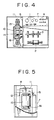
- the HIP machine of the just-mentioned publication has a base plate 8 securely fixed to one side of a panel body 7 which mounts thereon pressure gauges 1, compressor 2, automatic valves 3, indicator lamps 4, manual valves 5 and press button switches 6.
- a high pressure container 10 is mounted on the base plate 8 through a bracket 9, and a press frame 11 which serves to support the axial force of the high pressure container 10 during HIP process is pivotally mounted on the same side of the base plate through hinges 12 for pivoting movements about a vertical axis 13 toward and away from the high pressure container 10.
- the high pressure container 10 has upper and lower closure plugs 15 and 16 in its upper and lower openings to be opened at the time of loading and unloading work.
- the holder frame 11 is brought into a holding position where it is mechanically engaged with the upper and lower plugs 15 and 16 of the high pressure container to support the axial force of the latter during the HIP process.
- the holder frame is locked in position by pins or hooks which are put into or out of locking position manually by an operator. Therefore, even if the high pressure container is filled with a gas, the pins or hooks can be removed to disengage the holder frame 11 from the high pressure container 10 as long as the gas pressure is at a low level, namely, as long as the axial force is small.
- the high pressure container 10 is usually filled with a pressurized inert gas of 2 - 3 kgf/cm2 to prevent corrosion during a rest period between termination of a HIP operation and initiation of a next operation. Accordingly, the holder frame has to be held in the locking position even during the rest period by manually applying the pins or hooks, but a dangerous accident may incur by a negligence on the part of the operator.
- the present invention contemplates to provide an interlock system for HIP forming press, which can lock the holder frame in a secure and reliable manner whenever necessary.
- an interlock system for an isostatic press machine of the type including a high pressure container having upper and lower closure plugs releasably in upper and lower openings to be used for loading and unloading work therethrough, and a holder frame for supporting the axial force of the container in a isostatic pressing phase of the press operation, the holder frame being pivotally supported at one side thereof for swinging movements about a vertical axis into and out of a holding position in engagement with the high pressure container, characterized in that the interlock system comprises: a lock mechanism constantly urged to lock the holder frame in the holding position; and a control means adapted to control the lock mechanism to maintain the lock on the holder frame when the internal pressure of the high pressure container is higher than a predetermined level and to release release the lock when lower than the predetermined level.
- the lock mechanism 31 is released by the control means 36 when the pressure in the high pressure container 22 is lower than the predetermined level, permitting to swing the holder frame 26 about the vertical axis 27 toward or away from the holding position.
- the lock mechanism 31 is urged into the locking position by the control means 36 to lock the holder frame 26 in the holding position. Accordingly, there is no possibility of the plugs 23 and 24 of the container being blown off even when an operator forgets to apply the lock mechanism 31 or even in the event of an operation error.
- the lock mechanism 31 is constantly urged in the locking direction, the holder frame 26 can be locked securely even when power supply to the control means 36 is cut off.
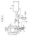
- a panel body which is provided with a base plate 21 at one side thereof.
- the reference 22 denotes a high pressure container which is provided with upper and lower closure plugs 22 and 23, and mounted on the base plate 21 through a bracket 25.
- Indicated at 26 is a holder frame which serves to support the axial force of the high pressure container 22 and which has one side thereof swingably or pivotally supported on the base plate 21 by a bracket 28 so that it can be manually moved toward and away from the high pressure container 22.
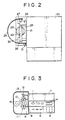
- a lock mechanism 31 is provided between the base plate 21 and the free end of a steel cover plate 29 which is securely fixed to the holder plate 26 through a support member 30.
- the lock mechanism 31 includes, as shown particularly in Fig. 1, a lock plate 32 which is securely fixed on the cover plate 29, a lock pin 33 which is releasably engageable with the lock plate 32, and an air cylinder 34 which is mounted on the base plate 21 for locking and releasing the lock pin 33.
- the air cylinder 34 incorporates a biasing spring 35 which constantly urges the lock pin to protrude in the locking direction.
- the air cylinder 34 of the lock mechanism 31 is operated by a control means 36 to lock the holder frame 26 when the pressure in the high pressure container 22 is higher than a predetermined level and to release the lock when lower than the predetermined level.
- the control means 36 is constituted by a pressure switch 38 which is connected to a processing gas conduit 37 leading to the pressure container 22, a comparator 39 adapted to compare the pressure signal from the pressure switch 38 with a preset value, and an electromagnetic valve 40 which is driven by the output of the comparator 39.
- the electromagnetic valve 40 is inserted in an air conduit 42 which connects the air cylinder 34 with an air source 41.
- Another electromagnetic valve 43 which is inserted in the processing gas conduit 37 is rendered operable by a limit switch 44 which detects whether or not the holder frame 26 is in the holding position. Namely, the electromagnetic valve 43 is operated under interlock control in such a manner that it is rendered inoperable unless the limit switch 44 is actuated.
- the electromagnetic valve 40 is energized by the output of the comparator when the pressure in the high pressure container 22 is lower than a predetermined level, operating the air cylinder 34 against the action of the spring 35 to disengage the lock pin 33 from the lock plate 32. Consequently, the holder frame 26 becomes free and can be turned about the vertical axis 27 by manual efforts.
- the limit switch 44 is actuated to permit opening of the electromagnetic valve 43. Therefore, the processing gas can be filled in the high pressure container 22 upon opening the electromagnetic valve 43 by a manual operation.
- the gas pressure is detected by the pressure switch 38 and, if the pressure in the container 22 becomes higher than a preset value, for example, higher than 1 kgf/cm2, the electromagnetic valve 40 is de-energized by the output of the comparator 39, opening the air cylinder 34 to the atmosphere.
- the lock pin 33 is protruded to engage the lock plate 32, automatically locking the holder frame 26 securely in the holding position to prevent blow-off of the closure plugs 23 and 24 of the high pressure container 22 which would otherwise take place when the lock mechanism 31 is inadvertently unlocked or erroneously operated.
- the power switch is cut off when the machine is at rest, but the lock pin 33 is constantly urged into the protruded position by the biasing spring 35 to retain the holder frame 26 securely in locked state.
- the lock mechanism 31 and control means 36 are not restricted to the particular construction or form shown, and may be arranged in a different way to perform the functions described above. Further, the lock mechanism 31 may be provided within the cover plate 29 if desired.
- the interlock system of the invention employs the lock mechanism 31 which constantly urges the holder frame 26 into the holding position in combination with the control means 36 which is adapted to apply the lock when the pressure in the high pressure container is higher than a predetermined level and to release the lock when lower than the predetermined level. Therefore, the holder frame 26 is securely locked in the holding position by the lock mechanism 31 as long as the pressure in the container is greater than a predetermined value, preventing the accidents which would result from a negligence or operation error in locking the holder frame and maintaining the locked state even after the power supply has been cut off.
Landscapes
- Physics & Mathematics (AREA)
- Fluid Mechanics (AREA)
- Engineering & Computer Science (AREA)
- Mechanical Engineering (AREA)
- Powder Metallurgy (AREA)
- Presses And Accessory Devices Thereof (AREA)
- Pressure Vessels And Lids Thereof (AREA)
- Press Drives And Press Lines (AREA)
Applications Claiming Priority (2)
| Application Number | Priority Date | Filing Date | Title |
|---|---|---|---|
| JP1051695A JPH02230082A (ja) | 1989-03-02 | 1989-03-02 | 静水圧成形プレスのインターロック装置 |
| JP51695/89 | 1989-03-02 |
Publications (2)
| Publication Number | Publication Date |
|---|---|
| EP0385494A2 true EP0385494A2 (de) | 1990-09-05 |
| EP0385494A3 EP0385494A3 (de) | 1991-08-28 |
Family
ID=12894037
Family Applications (1)
| Application Number | Title | Priority Date | Filing Date |
|---|---|---|---|
| EP19900104086 Withdrawn EP0385494A3 (de) | 1989-03-02 | 1990-03-02 | Gegenseitiges Verriegelungssystem für eine isostatische Formpresse |
Country Status (3)
| Country | Link |
|---|---|
| US (1) | US5009584A (de) |
| EP (1) | EP0385494A3 (de) |
| JP (1) | JPH02230082A (de) |
Families Citing this family (5)
| Publication number | Priority date | Publication date | Assignee | Title |
|---|---|---|---|---|
| WO2006082760A1 (ja) | 2005-02-01 | 2006-08-10 | Tosoh Corporation | 焼結体、スパッタリングターゲット及び成形型並びにそれを用いた焼結体の製造方法 |
| KR100892531B1 (ko) * | 2007-12-13 | 2009-04-10 | 기아자동차주식회사 | 헤밍 프레스의 자동 안전장치 |
| RU2467833C1 (ru) * | 2011-06-24 | 2012-11-27 | Открытое акционерное общество Акционерная холдинговая компания "Всероссийский научно-исследовательский и проектно-конструкторский институт металлургического машиностроения имени академика Целикова" (ОАО АХК "ВНИИМЕТМАШ") | Газостат |
| RU2467831C1 (ru) * | 2011-06-24 | 2012-11-27 | Открытое акционерное общество Акционерная холдинговая компания "Всероссийский научно-исследовательский и проектно-конструкторский институт металлургического машиностроения имени академика Целикова" (ОАО АХК "ВНИИМЕТМАШ") | Газостат |
| CN102229252A (zh) * | 2011-07-11 | 2011-11-02 | 陈小英 | 静等压机的控制装置及控制方法 |
Family Cites Families (10)
| Publication number | Priority date | Publication date | Assignee | Title |
|---|---|---|---|---|
| GB744789A (en) * | 1952-07-08 | 1956-02-15 | Weston Electrical Instr Corp | Improvements in or relating to safety arrangement for pressure vessels |
| GB840569A (en) * | 1957-01-05 | 1960-07-06 | Gunter Scholz | Improvements in or relating to safety devices for preventing the premature opening of pressure containers |
| US3566450A (en) * | 1968-01-25 | 1971-03-02 | Kennametal Inc | High pressure cylinder and press structure for the cylinder |
| US3931382A (en) * | 1973-05-11 | 1976-01-06 | National Forge Company | Method for rapid isostatic pressing |
| US4155476A (en) * | 1977-12-21 | 1979-05-22 | Autoclave Engineers, Inc. | Hanging reaction frame assembly |
| DE3236680C2 (de) * | 1981-10-05 | 1985-11-14 | Kobe Steel, Ltd., Kobe, Hyogo | Isostatische Heißpreßvorrichtung |
| JPS5857481B2 (ja) * | 1981-10-24 | 1983-12-20 | 株式会社神戸製鋼所 | 熱間静水圧成形方法および装置 |
| JPS58157300U (ja) * | 1982-04-13 | 1983-10-20 | 株式会社神戸製鋼所 | 熱間静水圧成形装置 |
| JPS6121296U (ja) * | 1984-07-13 | 1986-02-07 | 株式会社神戸製鋼所 | 高圧装置 |
| US4750635A (en) * | 1987-02-09 | 1988-06-14 | Wsf Industries, Inc. | Safety latch mechanism for closure of a pressure vessel |
-
1989
- 1989-03-02 JP JP1051695A patent/JPH02230082A/ja active Granted
-
1990
- 1990-03-02 EP EP19900104086 patent/EP0385494A3/de not_active Withdrawn
- 1990-03-02 US US07/487,444 patent/US5009584A/en not_active Expired - Fee Related
Also Published As
| Publication number | Publication date |
|---|---|
| JPH02230082A (ja) | 1990-09-12 |
| EP0385494A3 (de) | 1991-08-28 |
| JPH0529836B2 (de) | 1993-05-06 |
| US5009584A (en) | 1991-04-23 |
Similar Documents
| Publication | Publication Date | Title |
|---|---|---|
| US5009584A (en) | Interlock system for isostatic forming press | |
| ES2011933A6 (es) | Cerradura de puerta para automoviles. | |
| CA2133437C (en) | Feed device for fixing means | |
| US5727442A (en) | Safety device at hydraulic piston-cylinder units | |
| EP0245927B1 (de) | Lastenauslösehaken für Hubschrauber | |
| US5645793A (en) | Cartridge handling hand of a cartridge system sliding valve apparatus for a molten metal vessel | |
| EP1224064B1 (de) | Manuelle vorrichtung zum wechseln von werkzeugen | |
| US5417143A (en) | Lock-out mechanism for empty/load changeover valve | |
| JP4070281B2 (ja) | シリンダキャビネット | |
| CA2006923A1 (en) | Method and equipment for the transfer of a cargo space onto a vehicle and off the vehicle | |
| ES1029301U (es) | Mecanismo de cierre y sujecion de maletas para motocicletas y vehiculos similares. | |
| US4750635A (en) | Safety latch mechanism for closure of a pressure vessel | |
| EP0277921B1 (de) | Vorrichtung zum schnellen Verbinden eines Abzugsmechanismus mit einem Feuerwaffengehäuse | |
| US6698842B1 (en) | Dump truck end gate locking system | |
| US6568554B2 (en) | Hydraulic or pneumatic safety device for fluid handling apparatus | |
| JP3688592B2 (ja) | ロック解除状態保持機構 | |
| CN114008273A (zh) | 具有锁定特征的用于液压机的可动控制模块 | |
| GB2183713A (en) | Twistlocks | |
| US5489112A (en) | Hitch mount | |
| WO1993000246A1 (en) | A tilting device for a vehicle with a resiliently suspended tiltable cab | |
| WO1999055616A1 (en) | Lifting-machine power gripper and components | |
| EP0962401B1 (de) | Ladevorrichtung für eine mit einer Sicherungseinrichtung versehenen Müllsammelvorrichtung | |
| JP3045470B2 (ja) | ガソリンスタンドにおける荷卸し時の混油防止装置 | |
| EP4039511B1 (de) | Verriegelungssystem an der kugel eines zughakens für kraftfahrzeuge | |
| JPH0336337A (ja) | ショベルローダのリフトアーム下降防止装置 |
Legal Events
| Date | Code | Title | Description |
|---|---|---|---|
| PUAI | Public reference made under article 153(3) epc to a published international application that has entered the european phase |
Free format text: ORIGINAL CODE: 0009012 |
|
| AK | Designated contracting states |
Kind code of ref document: A2 Designated state(s): DE FR GB |
|
| PUAL | Search report despatched |
Free format text: ORIGINAL CODE: 0009013 |
|
| AK | Designated contracting states |
Kind code of ref document: A3 Designated state(s): DE FR GB |
|
| 17P | Request for examination filed |
Effective date: 19920221 |
|
| 17Q | First examination report despatched |
Effective date: 19930330 |
|
| STAA | Information on the status of an ep patent application or granted ep patent |
Free format text: STATUS: THE APPLICATION IS DEEMED TO BE WITHDRAWN |
|
| 18D | Application deemed to be withdrawn |
Effective date: 19930810 |