EP0385600A2 - Système pour poursuivre un avion dans une région. - Google Patents
Système pour poursuivre un avion dans une région. Download PDFInfo
- Publication number
- EP0385600A2 EP0385600A2 EP90301415A EP90301415A EP0385600A2 EP 0385600 A2 EP0385600 A2 EP 0385600A2 EP 90301415 A EP90301415 A EP 90301415A EP 90301415 A EP90301415 A EP 90301415A EP 0385600 A2 EP0385600 A2 EP 0385600A2
- Authority
- EP
- European Patent Office
- Prior art keywords
- aircraft
- station
- transponder
- receiving
- time
- Prior art date
- Legal status (The legal status is an assumption and is not a legal conclusion. Google has not performed a legal analysis and makes no representation as to the accuracy of the status listed.)
- Granted
Links
Images


Classifications
-
- G—PHYSICS
- G01—MEASURING; TESTING
- G01S—RADIO DIRECTION-FINDING; RADIO NAVIGATION; DETERMINING DISTANCE OR VELOCITY BY USE OF RADIO WAVES; LOCATING OR PRESENCE-DETECTING BY USE OF THE REFLECTION OR RERADIATION OF RADIO WAVES; ANALOGOUS ARRANGEMENTS USING OTHER WAVES
- G01S13/00—Systems using the reflection or reradiation of radio waves, e.g. radar systems; Analogous systems using reflection or reradiation of waves whose nature or wavelength is irrelevant or unspecified
- G01S13/74—Systems using reradiation of radio waves, e.g. secondary radar systems; Analogous systems
- G01S13/76—Systems using reradiation of radio waves, e.g. secondary radar systems; Analogous systems wherein pulse-type signals are transmitted
- G01S13/765—Systems using reradiation of radio waves, e.g. secondary radar systems; Analogous systems wherein pulse-type signals are transmitted with exchange of information between interrogator and responder
-
- G—PHYSICS
- G01—MEASURING; TESTING
- G01S—RADIO DIRECTION-FINDING; RADIO NAVIGATION; DETERMINING DISTANCE OR VELOCITY BY USE OF RADIO WAVES; LOCATING OR PRESENCE-DETECTING BY USE OF THE REFLECTION OR RERADIATION OF RADIO WAVES; ANALOGOUS ARRANGEMENTS USING OTHER WAVES
- G01S13/00—Systems using the reflection or reradiation of radio waves, e.g. radar systems; Analogous systems using reflection or reradiation of waves whose nature or wavelength is irrelevant or unspecified
- G01S13/74—Systems using reradiation of radio waves, e.g. secondary radar systems; Analogous systems
- G01S13/76—Systems using reradiation of radio waves, e.g. secondary radar systems; Analogous systems wherein pulse-type signals are transmitted
- G01S13/78—Systems using reradiation of radio waves, e.g. secondary radar systems; Analogous systems wherein pulse-type signals are transmitted discriminating between different kinds of targets, e.g. IFF-radar, i.e. identification of friend or foe
-
- G—PHYSICS
- G01—MEASURING; TESTING
- G01S—RADIO DIRECTION-FINDING; RADIO NAVIGATION; DETERMINING DISTANCE OR VELOCITY BY USE OF RADIO WAVES; LOCATING OR PRESENCE-DETECTING BY USE OF THE REFLECTION OR RERADIATION OF RADIO WAVES; ANALOGOUS ARRANGEMENTS USING OTHER WAVES
- G01S5/00—Position-fixing by co-ordinating two or more direction or position line determinations; Position-fixing by co-ordinating two or more distance determinations
- G01S5/0009—Transmission of position information to remote stations
-
- G—PHYSICS
- G01—MEASURING; TESTING
- G01S—RADIO DIRECTION-FINDING; RADIO NAVIGATION; DETERMINING DISTANCE OR VELOCITY BY USE OF RADIO WAVES; LOCATING OR PRESENCE-DETECTING BY USE OF THE REFLECTION OR RERADIATION OF RADIO WAVES; ANALOGOUS ARRANGEMENTS USING OTHER WAVES
- G01S5/00—Position-fixing by co-ordinating two or more direction or position line determinations; Position-fixing by co-ordinating two or more distance determinations
- G01S5/02—Position-fixing by co-ordinating two or more direction or position line determinations; Position-fixing by co-ordinating two or more distance determinations using radio waves
- G01S5/06—Position of source determined by co-ordinating a plurality of position lines defined by path-difference measurements
Definitions
- the present invention relates to systems for accurately monitoring the position of aircraft. Specifically, a system is provided for accurately determining the position of military aircraft during flight training over a test area which has simulated fire control radar installations.
- ground installations typically include ground to air missiles which are radar-guided.
- ground radar pulses When a pilot encounters hostile territory, the aircraft will be illuminated with ground radar pulses. The pilot must be trained to effectively maneuver the aircraft to avoid the consequences, i.e., missiles which are fired in response to position information derived from these radar signals.
- the aircraft is equipped with electronic warfare equipment which identifies when the aircraft is being illuminated by such radar. The pilot must enter into an active jamming role and evasive maneuvering routine to avoid the consequences of such ground defense systems.
- training flights are conducted over training areas which include simulated missile defense systems.
- simulated missile defense systems include radar beacons which simulate the fire control radar of missile defense systems.
- the radar tracking systems for position tracking of military aircraft over these training sites is expensive. Relocating the test site to provide different terrain in which a pilot is to train requires relocation of these sophisticated ground track radars. The expense and complications associated with re-establishing a new test site are avoided by a tracking system which is provided in accordance with this invention.
- the present invention makes use of conventional transponder equipment located on board the aircraft as a source of tracking data. Emissions from the aircraft transponder are used in an inverse Loran position determining system for establishing longitudinal and latitudinal coordinates for the aircraft.
- a plurality of receiving stations are positioned around the the test range. Aircraft flying through the test range include a squitter transmitter which will interrogate a conventional airborne IFF transponder to transmit its altitude and identity on a continuous basis to the ground receiving stations.
- the ground receiving stations have accurate clocks which are synchronized with each other.
- the synchronized receiving stations note the time of arrival of a transmission from the on-board transponder of the aircraft.
- each of the receive stations are linked to a master receive station through a wide band data link.
- This two-way data link will permit the master station to calibrate the remote station clocks, as well as receive data emitted by the aircraft passing through the test site identifying the time of arrival of transponder transmissions to the receiving stations.
- the master can calculate X-Y coordinates for the aircraft from time of arrival information produced from each of the respective receive stations. Additionally, altitude information, which is transmitted as part of the reply of the IFF transponder, is available to constantly monitor the height of the aircraft.
- the aircraft need only include a small squitter transmitter for interrogating the standard IFF transponder on the aircraft.
- the squitter transmitter may be configured to interrogate the IFF transponder on an asynchronous basis, which reduces the possibility of collisions with replies from other aircraft transponders in the general vicinity.
- the transmission of a TACAN pulse is used to initiate interrogation of the aircraft IFF transponder.
- Each of the receive locations receive not only the IFF reply containing altitude data, but the TACAN pulse. If each aircraft is previously assigned a TACAN frequency, the altitude and TACAN frequency may be correlated so that the identity of the aircraft is known.
- the foregoing system permits configuration of a test site without requiring active radar, with precision positioning pedestals and communication systems for accurately monitoring the aircraft position.
- the aircraft training site has boundaries which are identified by a quadrilateral, the corners of each quadrilateral including a receive station 15, 16, 17 and 18.
- One of the receive stations, 15, is a master station which, via a two-way communication link, collects data from the other receive stations.
- the training site will include several ground radar simulating sources 8.
- the aircraft 11, 12 will fly against the radar simulating beacons and exercise evasive maneuvers.
- the on-board transponder equipment such as the conventional IFF transponders contained on military aircraft, as well as commercial aircraft, are constantly interrogated by a squitter transmitter, also fixed to the aircraft 11, 12.
- the interrogated transponder transmits the required reply containing altitude information and identification information of the aircraft.
- Each of the receive stations 15, 16, 17 and 18 includes a local clock, synchronized with the master station 15 local clock.
- the time of arrival for the transponder transmissions are noted at each station, and transmitted to the master station 15 via a communication links.
- the time of arrival as is known from conventional Loran principles, can be used from a minimum of three (3) stations to determine the location of the aircraft in longitude and latitude. Additional stations may be employed, giving redundancy and an increase in accuracy of position measurement.
- Time of arrival information is used in other Loran type navigation systems.
- two receiving stations can define a line of position for an aircraft based on a difference in time of arrival of a radio transmission from an aircraft.
- the position along the line can be identified by a third receiving station which permits the creation of a second line of position which intersects the first line of position.
- the master station 15 includes a computer which will build a table of time of arrival measurements for each of the receive locations as the aircraft proceeds through the training site.
- the master station will determine the aircraft position for each instant of time the aircraft is over the training site.
- the IFF transponder transmits an altitude measurement as part of its reply to the interrogation pulse, as well as aircraft identity, so that the time of arrival information, for determining the longitude and latitude of the aircraft as well as altitude information is available for assessment of the training exercise.
- a squitter transmitter is attached to the aircraft to interrogate the IFF transponder, which is conventionally provided on the aircraft, at periodic intervals. This makes use of the available IFF transponder without burdening the aircraft with additional hardware.
- the squitter transmitter is a small package which is fastened to the aircraft strut or weapon holder by conventional means.
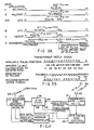
- FIG 2 there is shown the equipment package carried by the aircraft for emitting standard IFF replies on a periodic basis.
- the squitter generator 22 will produce the standard interrogation pulses as shown in Figure 3A on a random basis. Using a random trigger 21, the squitter generator 22 is enabled on a random basis. By randomizing the interrogation of the IFF transponder 27, the possibility of collisions with the replies from other aircraft in the vicinity of the one of interest can be avoided.
- the squitter generator 22 includes a small antenna 23 for radiating to antenna 26 of the IFF transponder 27.
- the squitter generator 22 and random trigger 21 is conveniently mounted in an area of the aircraft, which would permit reliable interrogation of the IFF transponder 27.
- the squitter package may be conveniently mounted on the armament support which is provided on military aircraft. Power is conventionally supplied on these armament supports and is used to power the squitter generator 22 and random trigger 21 of Figure 2.
- the squitter package of Figure 2 could emit mode C interrogation pulses so that the height of the aircraft would be repeatedly reported to the ground.
- the squitter package 21, 22 interrogate the transponder in accordance with modes A and C. Mode A will initiate interrogation pulses P1, P2 and P3 as shown in Figure 3A.
- transponder reply as shown in Figure 3B, having a pulse pattern which defines the identity of the aircraft.
- Mode C interrogations follow 125 microseconds later which generate a transponder reply which contains data identifying the height of the aircraft.
- the spacing between the successive pairs of replies is nominally 50,000 microseconds, however, an internal time base generator is combined with the pseudorandom trigger generator 22 so that the actual period varies in a statistically random manner.
- Triggering the transponder 27 in this way will reduce the likelihood of collisions on aircraft which are physically close to each other, and have randomly triggered transponder 27 transmissions.
- the ground stations of Figure 1 collect and correlate the received identity information from mode 3-a interrogation and height information from mode C interrogation. This data will be received in a constant 125 microsecond interval, making it easy for each of the ground stations to correlate the aircraft identity with its height.
- the squitter generator 22 may include a disable switch 24 connected to the squitter generator 22.
- the disable switch 24 is enabled once the aircraft has returned to the ground, thus disabling squittering of the IFF transponder 27 until another training run commences.
- Switch 24 may be connected to the landing gear and operated when the aircraft is on the ground.
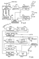
- FIG. 4 A block diagram of the remote receiving sites 16, 17 and 18 are shown in Figure 4.
- Figure 4 illustrates a wide band data link transmit/receive station 31 connected to an antenna 30 which is a microwave antenna, positioned to communicate with the master receive station 15.
- the wide band data link will permit synchronization of local clocks 36 at each of the remote receive locations with the master clock at the master station 15. Additionally, the recovered reply data from the IFF transponders and time of arrival information is transmitted back to the master station 15 over this wide band data link.
- the replies from the IFF transponder 27 are received on antenna 33 at the conventional IFF reply frequency of 1090 MHz.
- the IFF receiver and decoder 34 will provide for three different quantities of data.
- the conventional identity and altitude data transmitted as part of the mode interrogation of the aircraft transponder 27 is decoded and supplied to output ports 39 and 40.
- the time of arrival of the altitude or identity information is computed for each transmission of the transponder reply. This time of arrival data appears on output port 38.
- the time of arrival data is that time noted by the IFF receiver when the framing pulses of a reply are received.
- a counter within the IFF receiver 34 which is under control of real time clock 36, will note the occurrence of each pulse event received and will be cleared following the successful decode of both identity and altitude information.
- a time of arrival for the pulse train may be computed based on a running average of framing pulse arrivals or on the arrival of any of the identity or altitude data, as selected by the system designer.
- a message assembler 47 will compose the real time arrival data, identity data and altitude data into a message for modulating on the carrier signal of the wide band communication link.
- the wide band communication link station 31 will receive this modulation stream and transmit it to the master station 15.
- the master station In order for the master station to receive correlated time of arrival data for each of the receive locations, it is required that the real time clock 36 at each receive location be in synchronism. Thus, during a calibration sequence, the wide band data link will provide calibration data from the master station 15 used to synchronize each clock 36 at each receive location, so that during actual test runs, the time of arrival data from each receiver is synchronized with each other receiver.
- a real time clock calibration and control network 49 is used during a calibration interval to receive clock data from the wide band data link, decode the same and provide a frequency/phase control signal 43 to the real time clock 36.
- This frequency/phase control signal is the result of comparing the actual time of the real time clock 36 via output port 42 with a received real time from the master station 15. In this way, each of the real time receive clocks 36 can be synchronized.
- the master receive station is shown in Figure 5 which, is very similar to the remote receive stations of Figure 4.
- An IFF receiver 68 connected to an IFF antenna 71, receives at the master location, both time of arrival data, and identity and altitude information from a transponder reply.
- the message assembler 69 arranges this message in a frame which can be delivered to a central processor 66.
- Similar messages are received from each of three remote receive locations, via individual data links.
- a wide band data link comprising the transmit/receive station 61 is used to communicate with the first remote receive location. Additional data link stations 63 communicate with the remaining remote receive locations.
- the central processor 66 can collect the assembled data package comprising altitude, identity and time of arrival data from each of the remote locations.
- the central processor 66 is a general purpose digital computer which includes a table for each receive station storing the most recent packet of received position and identity data from each receive location.
- four tables can be built within the central processor 66 which will identify the identity and corresponding altitude and time of arrival data for each aircraft entering the training site. These tables can maintain time of arrival data for more than one aircraft since each time of arrival is correlated with each aircraft identity.
- latitude and longitude may be computed from time of arrival data obtained at three receive locations.
- the fourth time of arrival data can be used to permit a series of calculations to be accomplished between combinations of three receive stations. Any errors in data can be discarded in favor of the three most correlated computations for longitudinal and latitude position determination. Reporting of the position coordinates for aircraft in the training site can be sent by telephone link or displayed locally in an convenient manner.
- each of the receive locations requires only that the clocks at each receive location be synchronized.
- the RTR master clock 67 time can be transmitted to each of the receive locations over the data links represented by transmit/receive stations 61 through 63. It will be recognized that to achieve accurate synchronism between remotely located clocks and the master clock 67, calibration shall be required at each receive station to compensate for path delay experienced by transmission of clock information from the master station to each of the receive stations.
- the receive portion of the data link station 34a is shown having an output which can be directly connected to the local clock 36 through an input 45 or to a path delay adjustment circuit 49a.
- Switch 52 can be controlled so that data identifying the clock frequency is transferred to the local clock 36 from the receive link 34a. Additionally, test signals sent over the receive link 34a may be routed via switch 52 through the path delay adjustment circuit 49a, through switch 52 back over the transmit link 34b portion of the station 34.
- the master station will transmit a tone over the wide band data link to the receive portion 34a of the remote data link station. The receive tone enters the path delay adjustment circuit 49a and through switch 52 is applied to the transmitter 34b of the wide band data link station.
- the communication path delay adjustment 49a and 49b are adjusted in tandem so that the path delay from the input of receiver 34a to the output of transmitter 34b shows no net phase shift to incoming and outgoing tones. With the path delay correction circuit 49b set to equal that of 49a, delays within the receive station are effectively compensated.
- the retransmitted tone from transmitter 34b when received at the master station, will include delays which are only from the data link path, principally resulting from the distance between receive and master station.
- the incoming tones are measured with respect to the outgoing tone.
- an accurate measurement of the time delay between receive and transmit stations may be made.
- This quantity represents the two-way delay for the path length between master receive station and remote receive station.
- this two-way delay is divided by two and a corrected local time is transmitted by the master to the receive local clock 36.
- local clocks 36 are calibrated with a clock time corrected for path delay.
- Each of the receive locations will have local clocks 36 calibrated so that the time of arrival of transponder replies will be loaded in a corresponding register 47c at each location.
- This time of arrival data may typically be as much as 20 bits wide and include the entire pair of replies, altitude and identity. The time of arrival may be measured against any of the reply bits which are in the register 47c.
- transponder 27 which has previously been used on aircraft. Only the addition of a squitter generator 22 which can be conveniently mounted to a weapons carrying fixture on the aircraft.
- a calibration transponder 9 may be located within the training area as is shown in Figure 1.
- the transponder 9 is also operated in a squitter mode, preferably at a lower squitter rate such as 1 transmission per second, emitting both an identity and altitude transmission which is received by each receive station 15-18.
- the distances between each of the receive stations and the transponder 9 is precisely known.
- Each receive station will note the time of arrival using its internal receive clock just as it does when tracking aircraft through the sector.
- the time of arrival for these transmissions is reported to the master station.
- an expected time of arrival for each of these distances is also known.
- the master station computer will compare the expected time of arrival data with actual time of arrival data.
- the master station can compute clock offset corrections for each receive station real time clock, and modify subsequent time of arrival information received from a target aircraft. This calibration technique does not require an outgoing data link from the master station to each receive station. Additionally, this permits verification of the tracking system operation before in flight measurements begin.
- TACAN transmitter on the aircraft will interrogate position location transponder on the ground. Rather than use a squitter transmitter, it is possible to initiate a mode C interrogation of the aircraft IFF transponder based on TACAN interrogation pulses.
- a cross-link circuit as shown in Figure 7 may be employed, so that TACAN interrogations emitted by the aircraft are used to interrogate the IFF transponder.
- a crystal video detector 71 is shown connected to a small receiving antenna 70.
- TACAN interrogation pulses which are RF pulses of several hundred watt magnitude are received by the detector 71.
- the resulting pulse therefrom is decoded in decoder 72.
- a delayed pulse provided by delay circuit 73 is used to initiate a mode C interrogation from a transmitter 75.
- mode C interrogation may be effected in response to a TACAN pulse.
- the mode C interrogation is supplied through antenna 77 as in the previous embodiment to interrogate the IFF transponder.
- TACAN interrogation pulses to trigger a mode C interrogation provides for an ability to identify transponder replies to the mode C interrogation without requiring a mode 1, 2 or 3 interrogation of the IFF transmitter.
- the remote sites can include a TACAN receiver as well as an IFF receiver and decoder.
- the particular channel of the TACAN receiver which receives a TACAN inquiry correlated with an IFF reply received at the receiving location, can be used to identify the aircraft. Since the TACAN inquiry initiates the IFF reply, they are time correlated, permitting the remote receiving site to correlate altitude with identity.
- a TACAN antenna 78 applies each received TACAN pulse to a TACAN receiver 79. Depending on the frequency of the TACAN pulse, the aircraft is identified. Different aircraft will be preassigned a different TACAN frequency.
- the IFF antenna 81 at the remote receive site is connected to the IFF receiver and decoder.
- the altitude and time of arrival information is once again compiled by a message assembler 87.
- the real time clock 84 is calibrated with the calibration and control circuitry 88 as was described with respect to the previous embodiment.
- a wide band data link is provided by a data station 85. Calibration as well as modulated position data is transmitted via the wide band data link station 85 back to the master station.
- altitude information would be derived by the mode C reply from the IFF transponder aboard the aircraft.
- Those skilled in the art will recognize that if one of the receive stations is positioned in elevation higher than the remaining receive stations, it is possible to locate the altitude of the aircraft, using time of arrival methods.
- the differences in height of each receive station permit not only longitudinal and latitudinal position coordinates to be derived but elevation coordinates as well.
Landscapes
- Engineering & Computer Science (AREA)
- Radar, Positioning & Navigation (AREA)
- Remote Sensing (AREA)
- Physics & Mathematics (AREA)
- General Physics & Mathematics (AREA)
- Computer Networks & Wireless Communication (AREA)
- Radar Systems Or Details Thereof (AREA)
- Forklifts And Lifting Vehicles (AREA)
- Supply Devices, Intensifiers, Converters, And Telemotors (AREA)
- Retarders (AREA)
- Position Fixing By Use Of Radio Waves (AREA)
Applications Claiming Priority (2)
| Application Number | Priority Date | Filing Date | Title |
|---|---|---|---|
| US30859489A | 1989-02-10 | 1989-02-10 | |
| US308594 | 1989-02-10 |
Publications (3)
| Publication Number | Publication Date |
|---|---|
| EP0385600A2 true EP0385600A2 (fr) | 1990-09-05 |
| EP0385600A3 EP0385600A3 (fr) | 1991-08-21 |
| EP0385600B1 EP0385600B1 (fr) | 1996-07-24 |
Family
ID=23194586
Family Applications (1)
| Application Number | Title | Priority Date | Filing Date |
|---|---|---|---|
| EP90301415A Expired - Lifetime EP0385600B1 (fr) | 1989-02-10 | 1990-02-09 | Système pour poursuivre un avion dans une région. |
Country Status (4)
| Country | Link |
|---|---|
| EP (1) | EP0385600B1 (fr) |
| AT (1) | ATE140799T1 (fr) |
| CA (1) | CA2009344C (fr) |
| DE (1) | DE69027872T2 (fr) |
Cited By (14)
| Publication number | Priority date | Publication date | Assignee | Title |
|---|---|---|---|---|
| AU645326B2 (en) * | 1990-07-13 | 1994-01-13 | Frans Herman De Haan | Device for identifying and localizing transponders |
| GB2250154B (en) * | 1990-11-21 | 1994-10-26 | Roke Manor Research | Apparatus and method for locating an object |
| EP0653643A3 (fr) * | 1993-11-16 | 1996-07-17 | Cardion Inc | Procédé et système pour surveiller des véhicules. |
| WO1998005977A1 (fr) * | 1996-08-01 | 1998-02-12 | Era A.S. | Procede de localisation d'objets et notamment d'aeronefs, et son systeme de mise en oeuvre |
| EP0729588A4 (fr) * | 1993-11-15 | 1999-09-15 | Wybron Inc | Systeme suiveur |
| GB2338374A (en) * | 1998-06-10 | 1999-12-15 | Motorola Ltd | Locating a mobile telephone using time of arrival measurements |
| DE4319352C2 (de) * | 1992-06-15 | 2002-07-18 | Cardion Newco Inc | System zur Erzeugung von Signalen für die Identifizierung von Flugzeugen |
| US6510106B2 (en) | 1999-04-20 | 2003-01-21 | Flight Refuelling Limited | Systems and methods for locating subsurface objects |
| WO2007003455A1 (fr) * | 2005-07-01 | 2007-01-11 | Roke Manor Research Limited | Appareil et procede permettant de determiner des retards de groupes de recepteurs dans un systeme de multilateration |
| WO2012069629A3 (fr) * | 2010-11-26 | 2012-11-01 | Deutsches Zentrum für Luft- und Raumfahrt e.V. | Système de guidage d'aéronef |
| CN103295442A (zh) * | 2013-05-17 | 2013-09-11 | 珠海翔翼航空技术有限公司 | 一种用于识别飞机所处的空中管制区域的方法 |
| US9849334B2 (en) | 2010-01-05 | 2017-12-26 | Isolynx, Llc | Systems and methods for analyzing event data |
| CN113221944A (zh) * | 2021-04-02 | 2021-08-06 | 西安理工大学 | 一种紫外光协作多传感器数据融合无人机敌我识别方法 |
| CN120630190A (zh) * | 2025-05-19 | 2025-09-12 | 七二(北京)科技有限公司 | 一种无人机敌我识别方法及系统 |
Families Citing this family (12)
| Publication number | Priority date | Publication date | Assignee | Title |
|---|---|---|---|---|
| US7889133B2 (en) | 1999-03-05 | 2011-02-15 | Itt Manufacturing Enterprises, Inc. | Multilateration enhancements for noise and operations management |
| US7782256B2 (en) | 1999-03-05 | 2010-08-24 | Era Systems Corporation | Enhanced passive coherent location techniques to track and identify UAVs, UCAVs, MAVs, and other objects |
| US7570214B2 (en) | 1999-03-05 | 2009-08-04 | Era Systems, Inc. | Method and apparatus for ADS-B validation, active and passive multilateration, and elliptical surviellance |
| US7739167B2 (en) | 1999-03-05 | 2010-06-15 | Era Systems Corporation | Automated management of airport revenues |
| US7908077B2 (en) | 2003-06-10 | 2011-03-15 | Itt Manufacturing Enterprises, Inc. | Land use compatibility planning software |
| US8446321B2 (en) | 1999-03-05 | 2013-05-21 | Omnipol A.S. | Deployable intelligence and tracking system for homeland security and search and rescue |
| US7777675B2 (en) | 1999-03-05 | 2010-08-17 | Era Systems Corporation | Deployable passive broadband aircraft tracking |
| US7667647B2 (en) | 1999-03-05 | 2010-02-23 | Era Systems Corporation | Extension of aircraft tracking and positive identification from movement areas into non-movement areas |
| US7612716B2 (en) | 1999-03-05 | 2009-11-03 | Era Systems Corporation | Correlation of flight track data with other data sources |
| US8203486B1 (en) | 1999-03-05 | 2012-06-19 | Omnipol A.S. | Transmitter independent techniques to extend the performance of passive coherent location |
| US7965227B2 (en) | 2006-05-08 | 2011-06-21 | Era Systems, Inc. | Aircraft tracking using low cost tagging as a discriminator |
| CN112230633B (zh) * | 2020-10-29 | 2025-09-09 | 北京信息科技大学 | 无人机操控训练的安全保护装置 |
Family Cites Families (3)
| Publication number | Priority date | Publication date | Assignee | Title |
|---|---|---|---|---|
| US3419865A (en) * | 1967-05-10 | 1968-12-31 | John P. Chisholm | Mobile emergency unit locating system |
| US3518674A (en) * | 1969-02-13 | 1970-06-30 | Urban Scient Corp | Mobile unit locating system |
| DE2460645A1 (de) * | 1971-07-28 | 1976-06-24 | Siemens Ag | Verfahren zur standortbestimmung von fahrzeugen und einrichtung zur durchfuehrung des verfahrens |
-
1990
- 1990-02-05 CA CA002009344A patent/CA2009344C/fr not_active Expired - Fee Related
- 1990-02-09 AT AT90301415T patent/ATE140799T1/de not_active IP Right Cessation
- 1990-02-09 DE DE69027872T patent/DE69027872T2/de not_active Expired - Lifetime
- 1990-02-09 EP EP90301415A patent/EP0385600B1/fr not_active Expired - Lifetime
Cited By (20)
| Publication number | Priority date | Publication date | Assignee | Title |
|---|---|---|---|---|
| AU645326B2 (en) * | 1990-07-13 | 1994-01-13 | Frans Herman De Haan | Device for identifying and localizing transponders |
| GB2250154B (en) * | 1990-11-21 | 1994-10-26 | Roke Manor Research | Apparatus and method for locating an object |
| DE4319352C2 (de) * | 1992-06-15 | 2002-07-18 | Cardion Newco Inc | System zur Erzeugung von Signalen für die Identifizierung von Flugzeugen |
| EP0729588A4 (fr) * | 1993-11-15 | 1999-09-15 | Wybron Inc | Systeme suiveur |
| EP0653643A3 (fr) * | 1993-11-16 | 1996-07-17 | Cardion Inc | Procédé et système pour surveiller des véhicules. |
| WO1998005977A1 (fr) * | 1996-08-01 | 1998-02-12 | Era A.S. | Procede de localisation d'objets et notamment d'aeronefs, et son systeme de mise en oeuvre |
| GB2338374A (en) * | 1998-06-10 | 1999-12-15 | Motorola Ltd | Locating a mobile telephone using time of arrival measurements |
| US6347228B1 (en) | 1998-06-10 | 2002-02-12 | Motorola, Inc. | Location apparatus and method in a mobile telecommunications system |
| US6510106B2 (en) | 1999-04-20 | 2003-01-21 | Flight Refuelling Limited | Systems and methods for locating subsurface objects |
| US7928908B2 (en) | 2005-07-01 | 2011-04-19 | Roke Manor Research Limited | Apparatus and method for determining receiver performance in a multilateration system |
| WO2007003455A1 (fr) * | 2005-07-01 | 2007-01-11 | Roke Manor Research Limited | Appareil et procede permettant de determiner des retards de groupes de recepteurs dans un systeme de multilateration |
| US9849334B2 (en) | 2010-01-05 | 2017-12-26 | Isolynx, Llc | Systems and methods for analyzing event data |
| US10420981B2 (en) | 2010-01-05 | 2019-09-24 | Isolynx, Llc | Systems and methods for analyzing event data |
| WO2012069629A3 (fr) * | 2010-11-26 | 2012-11-01 | Deutsches Zentrum für Luft- und Raumfahrt e.V. | Système de guidage d'aéronef |
| US9612312B2 (en) | 2010-11-26 | 2017-04-04 | Deutsches Zentrum Fuer Luft- Und Raumfahrt E. V. | Flight guidance system |
| CN103295442A (zh) * | 2013-05-17 | 2013-09-11 | 珠海翔翼航空技术有限公司 | 一种用于识别飞机所处的空中管制区域的方法 |
| CN103295442B (zh) * | 2013-05-17 | 2015-09-16 | 珠海翔翼航空技术有限公司 | 一种用于识别飞机所处的空中管制区域的方法 |
| CN113221944A (zh) * | 2021-04-02 | 2021-08-06 | 西安理工大学 | 一种紫外光协作多传感器数据融合无人机敌我识别方法 |
| CN113221944B (zh) * | 2021-04-02 | 2024-04-26 | 河北翌航航天科技有限公司 | 一种紫外光协作多传感器数据融合无人机敌我识别方法 |
| CN120630190A (zh) * | 2025-05-19 | 2025-09-12 | 七二(北京)科技有限公司 | 一种无人机敌我识别方法及系统 |
Also Published As
| Publication number | Publication date |
|---|---|
| DE69027872D1 (de) | 1996-08-29 |
| CA2009344C (fr) | 1994-12-06 |
| ATE140799T1 (de) | 1996-08-15 |
| EP0385600A3 (fr) | 1991-08-21 |
| DE69027872T2 (de) | 1997-02-13 |
| EP0385600B1 (fr) | 1996-07-24 |
Similar Documents
| Publication | Publication Date | Title |
|---|---|---|
| US5144315A (en) | System for accurately monitoring aircraft position during training exercises | |
| CA2009344C (fr) | Systeme precis de surveillance de la position d'un aeronef au cours d'exercices d'instruction | |
| EP0653643B1 (fr) | Procédé et système pour surveiller des véhicules | |
| US7477193B2 (en) | Method and system for elliptical-based surveillance | |
| US4866450A (en) | Advanced instrument landing system | |
| US6094169A (en) | Multilateration auto-calibration and position error correction | |
| US7170441B2 (en) | Target localization using TDOA distributed antenna | |
| US4215345A (en) | Interferometric locating system | |
| US5636123A (en) | Traffic alert and collision avoidance coding system | |
| CA1156339A (fr) | Systeme porte par satellite pour determiner la position d'un vehicule | |
| US5099245A (en) | Vehicle location system accuracy enhancement for airborne vehicles | |
| US4315609A (en) | Target locating and missile guidance system | |
| US7508344B2 (en) | Systems and methods for TDOA/FDOA location | |
| US4193073A (en) | Method and apparatus for position determination | |
| CA1267206A (fr) | Systeme d'atterrissage aux instruments | |
| CN102483456A (zh) | 用于空中交通管制的二次监视雷达系统 | |
| US3611379A (en) | Tracking system | |
| US5475393A (en) | Precision landing system | |
| US5363109A (en) | Method of correcting measurement errors caused by clock deviations in a secondary radar system | |
| US6424290B1 (en) | Narrowband passive differential tracking system (U) | |
| AU1593188A (en) | Multi-mode microwave landing system | |
| US3566404A (en) | Vehicle collision avoidance system | |
| US10942241B2 (en) | System for indoor and outdoor position measurement | |
| EP0175967B1 (fr) | Système de navigation, communication et surveillance basé sur le DME | |
| CN1009964B (zh) | 先进的仪表着陆系统 |
Legal Events
| Date | Code | Title | Description |
|---|---|---|---|
| PUAI | Public reference made under article 153(3) epc to a published international application that has entered the european phase |
Free format text: ORIGINAL CODE: 0009012 |
|
| AK | Designated contracting states |
Kind code of ref document: A2 Designated state(s): AT BE CH DE DK ES FR GB GR IT LI LU NL SE |
|
| PUAL | Search report despatched |
Free format text: ORIGINAL CODE: 0009013 |
|
| AK | Designated contracting states |
Kind code of ref document: A3 Designated state(s): AT BE CH DE DK ES FR GB GR IT LI LU NL SE |
|
| 17P | Request for examination filed |
Effective date: 19911008 |
|
| RAP1 | Party data changed (applicant data changed or rights of an application transferred) |
Owner name: CARDION, INC. |
|
| 17Q | First examination report despatched |
Effective date: 19931126 |
|
| GRAH | Despatch of communication of intention to grant a patent |
Free format text: ORIGINAL CODE: EPIDOS IGRA |
|
| RTI1 | Title (correction) | ||
| GRAH | Despatch of communication of intention to grant a patent |
Free format text: ORIGINAL CODE: EPIDOS IGRA |
|
| GRAA | (expected) grant |
Free format text: ORIGINAL CODE: 0009210 |
|
| AK | Designated contracting states |
Kind code of ref document: B1 Designated state(s): AT BE CH DE DK ES FR GB GR IT LI LU NL SE |
|
| PG25 | Lapsed in a contracting state [announced via postgrant information from national office to epo] |
Ref country code: GR Free format text: LAPSE BECAUSE OF FAILURE TO SUBMIT A TRANSLATION OF THE DESCRIPTION OR TO PAY THE FEE WITHIN THE PRESCRIBED TIME-LIMIT Effective date: 19960724 Ref country code: ES Free format text: THE PATENT HAS BEEN ANNULLED BY A DECISION OF A NATIONAL AUTHORITY Effective date: 19960724 Ref country code: BE Effective date: 19960724 Ref country code: AT Effective date: 19960724 Ref country code: CH Effective date: 19960724 Ref country code: LI Effective date: 19960724 Ref country code: DK Effective date: 19960724 |
|
| REF | Corresponds to: |
Ref document number: 140799 Country of ref document: AT Date of ref document: 19960815 Kind code of ref document: T |
|
| ITF | It: translation for a ep patent filed | ||
| REF | Corresponds to: |
Ref document number: 69027872 Country of ref document: DE Date of ref document: 19960829 |
|
| ET | Fr: translation filed | ||
| PG25 | Lapsed in a contracting state [announced via postgrant information from national office to epo] |
Ref country code: SE Effective date: 19961024 |
|
| ET | Fr: translation filed | ||
| REG | Reference to a national code |
Ref country code: CH Ref legal event code: PL |
|
| PG25 | Lapsed in a contracting state [announced via postgrant information from national office to epo] |
Ref country code: LU Free format text: LAPSE BECAUSE OF NON-PAYMENT OF DUE FEES Effective date: 19970228 |
|
| PLBE | No opposition filed within time limit |
Free format text: ORIGINAL CODE: 0009261 |
|
| STAA | Information on the status of an ep patent application or granted ep patent |
Free format text: STATUS: NO OPPOSITION FILED WITHIN TIME LIMIT |
|
| 26N | No opposition filed | ||
| REG | Reference to a national code |
Ref country code: FR Ref legal event code: TP |
|
| NLS | Nl: assignments of ep-patents |
Owner name: CARDION NEWCO, INC. |
|
| REG | Reference to a national code |
Ref country code: GB Ref legal event code: 732E |
|
| REG | Reference to a national code |
Ref country code: GB Ref legal event code: IF02 |
|
| PGFP | Annual fee paid to national office [announced via postgrant information from national office to epo] |
Ref country code: NL Payment date: 20020124 Year of fee payment: 13 |
|
| PG25 | Lapsed in a contracting state [announced via postgrant information from national office to epo] |
Ref country code: NL Free format text: LAPSE BECAUSE OF NON-PAYMENT OF DUE FEES Effective date: 20030901 |
|
| NLV4 | Nl: lapsed or anulled due to non-payment of the annual fee |
Effective date: 20030901 |
|
| PGFP | Annual fee paid to national office [announced via postgrant information from national office to epo] |
Ref country code: DE Payment date: 20090206 Year of fee payment: 20 |
|
| PGFP | Annual fee paid to national office [announced via postgrant information from national office to epo] |
Ref country code: GB Payment date: 20090204 Year of fee payment: 20 |
|
| PGFP | Annual fee paid to national office [announced via postgrant information from national office to epo] |
Ref country code: IT Payment date: 20090218 Year of fee payment: 20 |
|
| PGFP | Annual fee paid to national office [announced via postgrant information from national office to epo] |
Ref country code: FR Payment date: 20090213 Year of fee payment: 20 |
|
| REG | Reference to a national code |
Ref country code: GB Ref legal event code: PE20 Expiry date: 20100208 |
|
| PG25 | Lapsed in a contracting state [announced via postgrant information from national office to epo] |
Ref country code: GB Free format text: LAPSE BECAUSE OF EXPIRATION OF PROTECTION Effective date: 20100208 |
|
| PG25 | Lapsed in a contracting state [announced via postgrant information from national office to epo] |
Ref country code: DE Free format text: LAPSE BECAUSE OF EXPIRATION OF PROTECTION Effective date: 20100209 |