EP0385628A2 - Messinstrumente mit beweglicher Spule - Google Patents
Messinstrumente mit beweglicher Spule Download PDFInfo
- Publication number
- EP0385628A2 EP0385628A2 EP90301744A EP90301744A EP0385628A2 EP 0385628 A2 EP0385628 A2 EP 0385628A2 EP 90301744 A EP90301744 A EP 90301744A EP 90301744 A EP90301744 A EP 90301744A EP 0385628 A2 EP0385628 A2 EP 0385628A2
- Authority
- EP
- European Patent Office
- Prior art keywords
- coil
- axis
- instrument
- rotation
- supported
- Prior art date
- Legal status (The legal status is an assumption and is not a legal conclusion. Google has not performed a legal analysis and makes no representation as to the accuracy of the status listed.)
- Granted
Links
Images

Classifications
-
- G—PHYSICS
- G01—MEASURING; TESTING
- G01R—MEASURING ELECTRIC VARIABLES; MEASURING MAGNETIC VARIABLES
- G01R5/00—Instruments for converting a single current or a single voltage into a mechanical displacement
- G01R5/02—Moving-coil instruments
- G01R5/08—Moving-coil instruments specially adapted for wide angle deflection; with eccentrically-pivoted moving coil
-
- G—PHYSICS
- G01—MEASURING; TESTING
- G01R—MEASURING ELECTRIC VARIABLES; MEASURING MAGNETIC VARIABLES
- G01R1/00—Details of instruments or arrangements of the types included in groups G01R5/00 - G01R13/00 and G01R31/00
- G01R1/02—General constructional details
- G01R1/10—Arrangements of bearings
- G01R1/12—Arrangements of bearings of strip or wire bearings
Definitions
- This invention relates to moving coil measuring instruments.
- the invention relates to such instruments wherein the moving coil is supported for rotation about an axis defined by a pair of spaced support members mounted on a frame member of the instrument.
- One known moving coil measuring instrument of this kind includes a magnetic circuit having two pole pieces which define an annular gap across which a magnetic field extends, the annular gap being substantially coaxial with the axis of rotation of the coil and a portion of the coil being disposed in the gap.
- the interaction between an electrical current carried by the portion of the coil disposed in the gap and the magnetic field extending across the gap causes rotation of the coil, the angle through which the coil rotates indicating the value of the current carried by the coil.
- a moving coil measuring instrument wherein the moving coil is supported for rotation about an axis defined by a pair of spaced support members mounted on a frame member of the instrument, characterised in that at least one said support member is movable relative to said frame member whilst mounted thereon so as to permit adjustment of the position of an end of said axis defined by said one support member in a direction substantially perpendicular to said axis.
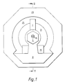
- the first instrument comprises a rectangular moving coil 1 supported for rotation about an axis 3 defined by a pair of spaced support members in the form of bushes 5, 7 mounted on a frame member 9 of the instrument.
- the coil 1 is supported by means of pivots 11, 13 which locate in jewels 15A, 17A carried by jewel screws 15, 17 which screw into tapped holes in the bushes 5, 7 respectively.
- the instrument has a magnetic circuit comprising a rectangular permanent magnet 19 and a pair of concentric annular pole pieces 21, 23 which produces a magnetic field extending radially across an annular gap 25 defined between facing surfaces of the pole pieces 21, 23, the gap 25 being substantially coaxial with the axis 3 of rotation of the coil 1, and one side 27 of the coil 1 being disposed in the gap 25.
- the bushes 5, 7 have hexagonal heads and are rotatably mounted in apertures extending through the frame member 9.
- the jewel screws 15, 17 are located in their respective bushes 5, 7 at positions such that their axes 29, 30 are parallel to but displaced from the axes 31, 32 of rotation of the bushes 5, 7.
- the interaction between an electrical current carried by the side 27 of the coil 1 and the magnetic field extending across the gap 25 causes rotation of the coil 1 and hence movement of the side 27 of the coil 1 around the annular gap 25 against the return force provided by a return spring (not shown), the distance the side 27 moves around the annular gap 25 indicating the value of the current carried by the coil 1.
- correction can be effected by rotation either of one or both of the bushes 5, 7 within the frame member 9 so as to adjust the position of the one or both ends of the axis of rotation 3 of the coil 1 defined by the bushes 5, 7 in a direction substantially perpendicular to the axis of rotation 3, such adjustment altering the disposition of the side 27 of the coil 1 in the gap 25.
- the second instrument is substantially the same as the first except that the moving coil 1 is supported for rotation by means of a taut band suspension instead of a jewel and pivot suspension.
- the taut band suspension is substantially the same on each side of the coil 1, and the suspension above the coil 1 only is therefore shown in Figure 3 and will be described.
- the suspension above the coil 1 comprises a taut band 37 supported at one end 38 by an inner bush 39, rotatably mounted in an outer bush 43 rotatably mounted on a frame member 9 of the instrument, and secured at the other end 40 to the top side of the coil by a clip 33.
- the end 38 is supported by the inner bush 39 by way of a spring 42 formed from thin sheet metal and of basically annular shape with outwardly extending rectangular lugs 44 and an inwardly extending arm 46 terminating with a smooth edge just before the centre of the spring 42.
- To the arm 46 is attached the end 38 of the band 37 so as to pass over the smooth edge.
- the spring 42 is held in position by abutment with the inner bush 39.
- the bush 39 is castellated at the end remote from the coil 1 so as to provide parallel sided axially extending slots 50 corresponding in number and position to the lugs 44.
- the spring 42 is positioned in the bush 39 with its lugs 44 abutting the bases of respective slots 50 of the bush 39.
- the outer bush 43 has a hexagonal head 49.
- the inner bush 39 is mounted in the outer bush 43 such that its axis 51 is parallel to but displaced from the axis of rotation 41 of the outer bush 43.
- Adjustment of the position of the axis of rotation 3 of the coil 1, and hence the position of the coil 1 in the gap 25 is effected, as in the Figure 1 instrument, by rotation of one or both of the outer bushes 43 in the frame 9.
- the inner bushes 39 are made rotatable in the outer bushes 43 so that changes in the zero position of the coil 1 produced by rotation of the outer bushes 43 can be cancelled by contra-rotation of the inner bushes 39.
Landscapes
- Physics & Mathematics (AREA)
- General Physics & Mathematics (AREA)
- Investigating Or Analyzing Materials By The Use Of Magnetic Means (AREA)
- Testing Of Short-Circuits, Discontinuities, Leakage, Or Incorrect Line Connections (AREA)
- A Measuring Device Byusing Mechanical Method (AREA)
- Measurement Of Length, Angles, Or The Like Using Electric Or Magnetic Means (AREA)
- Measuring Magnetic Variables (AREA)
- Reciprocating, Oscillating Or Vibrating Motors (AREA)
- Transmission And Conversion Of Sensor Element Output (AREA)
- Measuring Leads Or Probes (AREA)
Applications Claiming Priority (2)
| Application Number | Priority Date | Filing Date | Title |
|---|---|---|---|
| GB8904886 | 1989-03-03 | ||
| GB8904886A GB2229007B (en) | 1989-03-03 | 1989-03-03 | Moving coil measuring instruments |
Publications (3)
| Publication Number | Publication Date |
|---|---|
| EP0385628A2 true EP0385628A2 (de) | 1990-09-05 |
| EP0385628A3 EP0385628A3 (en) | 1990-10-17 |
| EP0385628B1 EP0385628B1 (de) | 1993-09-01 |
Family
ID=10652674
Family Applications (1)
| Application Number | Title | Priority Date | Filing Date |
|---|---|---|---|
| EP90301744A Expired - Lifetime EP0385628B1 (de) | 1989-03-03 | 1990-02-19 | Messinstrumente mit beweglicher Spule |
Country Status (7)
| Country | Link |
|---|---|
| US (1) | US5012184A (de) |
| EP (1) | EP0385628B1 (de) |
| AT (1) | ATE93973T1 (de) |
| DE (1) | DE69002966T2 (de) |
| DK (1) | DK0385628T3 (de) |
| ES (1) | ES2045790T3 (de) |
| GB (1) | GB2229007B (de) |
Family Cites Families (7)
| Publication number | Priority date | Publication date | Assignee | Title |
|---|---|---|---|---|
| US2963651A (en) * | 1957-12-16 | 1960-12-06 | English Electric Co Ltd | Instrument zero adjusters |
| US3624505A (en) * | 1969-06-26 | 1971-11-30 | Weston Instr Division | High-impact withstanding taut band suspension instrument |
| US3678383A (en) * | 1971-05-03 | 1972-07-18 | Weston Instruments Inc | High impact withstanding taut band suspension instrument |
| US4039944A (en) * | 1976-04-08 | 1977-08-02 | Montevideo Technology, Inc. | Moving coil electrical instrument |
| GB1576438A (en) * | 1977-06-23 | 1980-10-08 | Gen Electric Co Ltd | Moving coil indicating instruments |
| US4564806A (en) * | 1982-04-23 | 1986-01-14 | Kaise Denki Kabushiki Kaisha | Taut band instrument having accurate taut band positioning means |
| GB8604721D0 (en) * | 1986-02-26 | 1986-04-03 | Bpl Instr Ltd | Measuring instruments |
-
1989
- 1989-03-03 GB GB8904886A patent/GB2229007B/en not_active Expired - Fee Related
-
1990
- 1990-02-19 ES ES90301744T patent/ES2045790T3/es not_active Expired - Lifetime
- 1990-02-19 DE DE90301744T patent/DE69002966T2/de not_active Expired - Fee Related
- 1990-02-19 EP EP90301744A patent/EP0385628B1/de not_active Expired - Lifetime
- 1990-02-19 AT AT90301744T patent/ATE93973T1/de not_active IP Right Cessation
- 1990-02-19 DK DK90301744.0T patent/DK0385628T3/da active
- 1990-02-21 US US07/482,524 patent/US5012184A/en not_active Expired - Fee Related
Also Published As
| Publication number | Publication date |
|---|---|
| ES2045790T3 (es) | 1994-01-16 |
| US5012184A (en) | 1991-04-30 |
| DK0385628T3 (da) | 1993-10-25 |
| DE69002966T2 (de) | 1993-12-16 |
| GB2229007A (en) | 1990-09-12 |
| GB8904886D0 (en) | 1989-04-12 |
| GB2229007B (en) | 1993-02-24 |
| EP0385628A3 (en) | 1990-10-17 |
| DE69002966D1 (de) | 1993-10-07 |
| EP0385628B1 (de) | 1993-09-01 |
| ATE93973T1 (de) | 1993-09-15 |
Similar Documents
| Publication | Publication Date | Title |
|---|---|---|
| CA1149509A (en) | Magnetic transducing head mount | |
| EP0119064B1 (de) | Schocksensor mit Trägheitsschalter | |
| KR880001208Y1 (ko) | 모우터축의 수직조정장치 | |
| EP0176332B1 (de) | Optischer Aufnahmekopf | |
| EP0228227B1 (de) | Einrichtung, um einen axial bewegbaren Gegenstand in eine axial neutrale Stellung zu zwingen | |
| EP0385628B1 (de) | Messinstrumente mit beweglicher Spule | |
| EP0222565B1 (de) | Vorrichtung zum Zurückdrängen eines drehbaren Gliedes in eine neutrale Winkelstellung | |
| US3678383A (en) | High impact withstanding taut band suspension instrument | |
| US2545835A (en) | Relay | |
| US3277370A (en) | Taut band suspended instrument movement with shock resistant longitudinal movement stop | |
| JP2531521Y2 (ja) | 輻射スポットの位置を電気力学制御する電気光学装置 | |
| US4050021A (en) | Moving-coil measuring system with a large pointer deflection | |
| CA1205113A (en) | Electromagnetic switching device | |
| CA1093156A (en) | Compact moving coil meter | |
| GB2029600A (en) | Movable mirror device for optical information recording and reproducing system | |
| US2846542A (en) | Relay structure | |
| US3495200A (en) | Adjustable armature for an electromagnetic relay | |
| JPH0328380Y2 (de) | ||
| US3026478A (en) | figure | |
| US3041536A (en) | Pancake meters | |
| US4952870A (en) | Compact taut band meter movement assembly | |
| US2823353A (en) | Instrument bearing suspension | |
| JPH02259618A (ja) | 光偏向装置 | |
| US2957956A (en) | Electrical instrument type relay | |
| KR830000242Y1 (ko) | 가동(可動) 코일용 계기(形計器) |
Legal Events
| Date | Code | Title | Description |
|---|---|---|---|
| PUAI | Public reference made under article 153(3) epc to a published international application that has entered the european phase |
Free format text: ORIGINAL CODE: 0009012 |
|
| PUAL | Search report despatched |
Free format text: ORIGINAL CODE: 0009013 |
|
| AK | Designated contracting states |
Kind code of ref document: A2 Designated state(s): AT CH DE DK ES FR IT LI |
|
| AK | Designated contracting states |
Kind code of ref document: A3 Designated state(s): AT CH DE DK ES FR IT LI |
|
| 17P | Request for examination filed |
Effective date: 19910403 |
|
| 17Q | First examination report despatched |
Effective date: 19921029 |
|
| GRAA | (expected) grant |
Free format text: ORIGINAL CODE: 0009210 |
|
| AK | Designated contracting states |
Kind code of ref document: B1 Designated state(s): AT CH DE DK ES FR IT LI |
|
| REF | Corresponds to: |
Ref document number: 93973 Country of ref document: AT Date of ref document: 19930915 Kind code of ref document: T |
|
| ET | Fr: translation filed | ||
| ITF | It: translation for a ep patent filed | ||
| REF | Corresponds to: |
Ref document number: 69002966 Country of ref document: DE Date of ref document: 19931007 |
|
| REG | Reference to a national code |
Ref country code: DK Ref legal event code: T3 |
|
| REG | Reference to a national code |
Ref country code: ES Ref legal event code: FG2A Ref document number: 2045790 Country of ref document: ES Kind code of ref document: T3 |
|
| PLBE | No opposition filed within time limit |
Free format text: ORIGINAL CODE: 0009261 |
|
| STAA | Information on the status of an ep patent application or granted ep patent |
Free format text: STATUS: NO OPPOSITION FILED WITHIN TIME LIMIT |
|
| 26N | No opposition filed | ||
| PGFP | Annual fee paid to national office [announced via postgrant information from national office to epo] |
Ref country code: AT Payment date: 20010110 Year of fee payment: 12 |
|
| PGFP | Annual fee paid to national office [announced via postgrant information from national office to epo] |
Ref country code: FR Payment date: 20010111 Year of fee payment: 12 |
|
| PGFP | Annual fee paid to national office [announced via postgrant information from national office to epo] |
Ref country code: DK Payment date: 20010112 Year of fee payment: 12 |
|
| PGFP | Annual fee paid to national office [announced via postgrant information from national office to epo] |
Ref country code: DE Payment date: 20010119 Year of fee payment: 12 |
|
| PGFP | Annual fee paid to national office [announced via postgrant information from national office to epo] |
Ref country code: CH Payment date: 20010122 Year of fee payment: 12 |
|
| PGFP | Annual fee paid to national office [announced via postgrant information from national office to epo] |
Ref country code: ES Payment date: 20010207 Year of fee payment: 12 |
|
| PG25 | Lapsed in a contracting state [announced via postgrant information from national office to epo] |
Ref country code: AT Free format text: LAPSE BECAUSE OF NON-PAYMENT OF DUE FEES Effective date: 20020219 |
|
| PG25 | Lapsed in a contracting state [announced via postgrant information from national office to epo] |
Ref country code: ES Free format text: LAPSE BECAUSE OF NON-PAYMENT OF DUE FEES Effective date: 20020220 |
|
| PG25 | Lapsed in a contracting state [announced via postgrant information from national office to epo] |
Ref country code: LI Free format text: LAPSE BECAUSE OF NON-PAYMENT OF DUE FEES Effective date: 20020228 Ref country code: DK Free format text: LAPSE BECAUSE OF NON-PAYMENT OF DUE FEES Effective date: 20020228 Ref country code: CH Free format text: LAPSE BECAUSE OF NON-PAYMENT OF DUE FEES Effective date: 20020228 |
|
| PG25 | Lapsed in a contracting state [announced via postgrant information from national office to epo] |
Ref country code: DE Free format text: LAPSE BECAUSE OF NON-PAYMENT OF DUE FEES Effective date: 20020903 |
|
| REG | Reference to a national code |
Ref country code: DK Ref legal event code: EBP |
|
| REG | Reference to a national code |
Ref country code: CH Ref legal event code: PL |
|
| PG25 | Lapsed in a contracting state [announced via postgrant information from national office to epo] |
Ref country code: FR Free format text: LAPSE BECAUSE OF NON-PAYMENT OF DUE FEES Effective date: 20021031 |
|
| REG | Reference to a national code |
Ref country code: FR Ref legal event code: ST |
|
| PG25 | Lapsed in a contracting state [announced via postgrant information from national office to epo] |
Ref country code: IT Free format text: LAPSE BECAUSE OF NON-PAYMENT OF DUE FEES Effective date: 20050219 |