EP0385673A1 - Outil de fraisage pour fond de puits et élément de coupe pour cet outil - Google Patents
Outil de fraisage pour fond de puits et élément de coupe pour cet outil Download PDFInfo
- Publication number
- EP0385673A1 EP0385673A1 EP90301967A EP90301967A EP0385673A1 EP 0385673 A1 EP0385673 A1 EP 0385673A1 EP 90301967 A EP90301967 A EP 90301967A EP 90301967 A EP90301967 A EP 90301967A EP 0385673 A1 EP0385673 A1 EP 0385673A1
- Authority
- EP
- European Patent Office
- Prior art keywords
- cutting
- cutter
- blade
- tool
- range
- Prior art date
- Legal status (The legal status is an assumption and is not a legal conclusion. Google has not performed a legal analysis and makes no representation as to the accuracy of the status listed.)
- Granted
Links
Images

Classifications
-
- E—FIXED CONSTRUCTIONS
- E21—EARTH OR ROCK DRILLING; MINING
- E21B—EARTH OR ROCK DRILLING; OBTAINING OIL, GAS, WATER, SOLUBLE OR MELTABLE MATERIALS OR A SLURRY OF MINERALS FROM WELLS
- E21B29/00—Cutting or destroying pipes, packers, plugs or wire lines, located in boreholes or wells, e.g. cutting of damaged pipes, of windows; Deforming of pipes in boreholes or wells; Reconditioning of well casings while in the ground
- E21B29/002—Cutting, e.g. milling, a pipe with a cutter rotating along the circumference of the pipe
- E21B29/005—Cutting, e.g. milling, a pipe with a cutter rotating along the circumference of the pipe with a radially-expansible cutter rotating inside the pipe, e.g. for cutting an annular window
-
- E—FIXED CONSTRUCTIONS
- E21—EARTH OR ROCK DRILLING; MINING
- E21B—EARTH OR ROCK DRILLING; OBTAINING OIL, GAS, WATER, SOLUBLE OR MELTABLE MATERIALS OR A SLURRY OF MINERALS FROM WELLS
- E21B10/00—Drill bits
- E21B10/46—Drill bits characterised by wear resisting parts, e.g. diamond inserts
-
- E—FIXED CONSTRUCTIONS
- E21—EARTH OR ROCK DRILLING; MINING
- E21B—EARTH OR ROCK DRILLING; OBTAINING OIL, GAS, WATER, SOLUBLE OR MELTABLE MATERIALS OR A SLURRY OF MINERALS FROM WELLS
- E21B10/00—Drill bits
- E21B10/26—Drill bits with leading portion, i.e. drill bits with a pilot cutter; Drill bits for enlarging the borehole, e.g. reamers
- E21B10/32—Drill bits with leading portion, i.e. drill bits with a pilot cutter; Drill bits for enlarging the borehole, e.g. reamers with expansible cutting tools
- E21B10/322—Drill bits with leading portion, i.e. drill bits with a pilot cutter; Drill bits for enlarging the borehole, e.g. reamers with expansible cutting tools cutter shifted by fluid pressure
-
- Y—GENERAL TAGGING OF NEW TECHNOLOGICAL DEVELOPMENTS; GENERAL TAGGING OF CROSS-SECTIONAL TECHNOLOGIES SPANNING OVER SEVERAL SECTIONS OF THE IPC; TECHNICAL SUBJECTS COVERED BY FORMER USPC CROSS-REFERENCE ART COLLECTIONS [XRACs] AND DIGESTS
- Y10—TECHNICAL SUBJECTS COVERED BY FORMER USPC
- Y10T—TECHNICAL SUBJECTS COVERED BY FORMER US CLASSIFICATION
- Y10T408/00—Cutting by use of rotating axially moving tool
- Y10T408/89—Tool or Tool with support
- Y10T408/905—Having stepped cutting edges
- Y10T408/906—Axially spaced
Definitions
- This invention relates to a downhole milling tool and to a cutter therefor for cutting tubular members downhole.
- Downhole milling tools are well known and may consist of a tubular body having an axial aperture therethrough for circulation of cooling fluid and a plurality of equi-circumferentially disposed slots in the outer surface of the body. In each of the slots is located a pivotally mounted cutting blade and a means is provided for moving each of the cutting blades radially outwardly from the body. Each of the cutting blades has an outer surface facing the direction of rotation of the tool which is dressed with a cutting material.
- the dressing may be formed by crushed tungsten carbide chips which are randomly dispersed on the blade surface.
- crushed tungsten carbide chips because they have an irregular shape and size they are difficult to secure to the blade surface and such inconsistency in shape also leads to unpredictable performance in respect of swarf cutting configuration and rate of penetration.
- This problem has been alleviated by using tungsten carbide elements having a circular or rectangular cross-section, the tungsten carbide elements being brazed, soldered or welded to the blade.
- tungsten carbide elements of a regular shape may be located on the blade both radially and in an axial longitudinal direction of the blade in a regular formation such that each element provides a negative rake angle, that is, in use each blade is angled downwardly and rearwardly with respect to the vertical direction of the blade taken in the direction of rotation when in use.
- the known cutting elements of regular shape have been known to be provided with a chip breaker, that is a projection which limits the length of swarf cut by the cutting edge of the element.
- a chip breaker that is a projection which limits the length of swarf cut by the cutting edge of the element.
- Such known elements have only one chip breaker and once that is worn off the performance of the tool deteriorates until the next element with a new chip breaker is exposed.
- a cutter for a downhole milling tool which tool is rotatable about a longitudinal axis, said cutter comprising a blade having a cutting surface, said cutting surface being formed by a plurality of cutting elements, each cutting element having a plurality of protruding cutting edges each being longitudinally axially spaced from one another and interspaced by a recessed portion, whereby in use swarf moves upwardly from one of the cutting edges along said recessed portion and is subsequently broken off.
- Generally c-shaped swarf cuttings are thus preferably produced.
- the cutting surface extends in a generally radial direction across the intended direction of rotation of the tool and the cutting edges also extend generally radially. It is believed swarf cuttings will be assisted in moving under centrifugal force to the outer radial edge of a blade if preferably each cutting element has a negative radial rake, i.e. has a radial outer edge thereof disposed angularly rearward of a radius to the longitudinal direction with respect to a radial inner edge of said element, in the range 1-10 o and preferably 5 o , and the cutting edges are planar therewith.
- each cutting element is located on the blade at an angle inclined to a radial direction which is perpendicular to the longitudinal axis (herein referred to as the "lead attack angle") and the elements are positioned in the longitudinal direction one above the other so that the elements provide a continuous cutting surface.
- the lead attack angle is in the range 1-15 o and preferably 10 o .
- each cutting element is a discrete part, each of which is secured to the cutting blade by, for example, brazing or soldering or welding.
- the cutting elements of odd numbered rows extending longitudinally are in line and even numbered rows extending longitudinally are in line and the even numbered rows are offset in a radial direction by half the radial length of a cutting element from the odd numbered rows.
- each cutting element is arranged to produce a negative axial rake angle with respect to the plane of the longitudinal axis, which angle may be in the range 1-20 o and preferably in the range 7-10 o .
- each of the cutting elements is secured over a planar leading surface of the blade and each element has a front cutting face which is inclined with respect to the rear surface thereof, said rear surface abutting the blade so that the front cutting surface is provided with said negative axial rake angle.
- each cutting element has parallel front and rear faces and the leading face of the blade has a generally radial slot formed therein which is inclined in the longitudinal axial direction to present the front face of the cutting element with a negative axial rake angle.
- each cutting element has parallel front and rear faces and the leading face of the blade is formed in the longitudinal direction thereof in a staircase formation with the part thereof extending in the longitudinal direction being inclined whereby when the cutting elements are positioned on the parts thereof extending in the longitudinal direction, a leading surface of the cutting element presents a negative axial rake angle.
- each cutting element has parallel front and rear faces, the rear face being secured to a leading side of said blade and said blade being inclined with respect to the longitudinal axis to provide said negative axial rake angle.
- each of the cutting edges has a rake angle in the range 0-40 o , advantageously 3-12 o and a land angle in the range 0-35 o , preferably 3-15 o .
- the cutting elements are each quadrilateral in cross-section, conveniently square.
- the cutting elements extend both in a radial and a longitudinal direction over the blade leading face.
- the cutting edge protrudes from the recessed portion in the range 0.001-0.060 inches (0.025-1.5mm) preferably 0. 003-0.015 inches (0.076-0.38mm).
- each cutting element is made from tungsten carbide having European ISO standard P10 to P60 hardness grade and with a cobalt content in the range 7%-20%.
- each blade is located about the circumference of a tool body member and each blade is pivotally located to said body member.
- a rotatable milling tool for use downhole including a body having a longitudinal axis, a plurality of pivotally mounted blades circumferentially spaced around the body, slot means for receiving each blade in a contracted condition of said blade and means for radially extending each blade, each blade having a cutting surface formed by a plurality of cutting elements, each cutting element having a plurality of protruding cutting edges each being longitudinally axially spaced from one another and interspaced by a recessed portion, whereby in use swarf moves upwardly from one of the cutting edges along said recessed portion and is broken off when meeting the next, uppermost, cutting edge.
- the cutting surface extends in a generally radial direction across the intended direction of rotation of the tool and the cutting edges also extend generally radially.
- a milling tool for use in energy exploration, said tool being connectable to a drilling string and rotatable about a longitudinal axis, said tool having a cutter comprising a blade having a cutting surface, said cutting surface being formed by a plurality of cutting elements, each cutting element having a plurality of protruding cutting edges each being longitudinally axially spaced from one another and interspaced by a recessed portion, whereby in use swarf moves upwardly from one of the cutting edges along said recessed portion and is broken off when meeting the next, uppermost cutting edge.
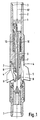
- the rotatable milling tool for use downhole shown in Figure 1 has a circularly cross-section body 1 having axial passages 2 therethrough for the circulation of fluid and the upper and lower ends of the body each have an internal screw thread 3 for connecting the body to a drill string and other apparatus respectively.
- the body may have three to twelve, preferably six, equi-circumferentially spaced longitudinal slots 4 provided in the outer circumference thereof.
- Three axially long cutters 5 interspaced by three axially short cutters 6 are each mounted on a respective pivot 7 in each of the slots 4 and a respective cam 8 carried by circulating fluid operated piston 9 acts on the cutters 5, 6 so that the cutter is pivotally radially movable away from the body 1 to a cutting position (the cutter 5 only being shown radially extended).
- the piston 9 is biassed by a compression spring 10. In operation the tool 1 is rotatable about a longitudinal axis 97.
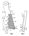
- One of the cutters 5 is shown in detail in Figures 2, 3, 4 and 5A and has a longitudinally extending blade 100, the upper end (as shown in Figure 2) being provided with a circular hole 11 through which the pivot 7 is located.
- the blade 100 has a necked portion 12 in which the hole 11 is situated which broadens out to a main portion 13, a radially inner side 14 along which cam 8 abrades linking to an approximately triangularly cross-sectioned rib 15.
- the lower part of the blade 100 has an L-shaped cutout to provide a lower, in use, edge 16.
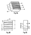
- a plurality of cutting elements 20 Located over a leading surface 17 of the blade, i.e. facing forwardly in the direction of rotation of the tool, is a plurality of cutting elements 20, each as shown in Figures 4A-4C, the elements being secured to the blade by any convenient means known per se such as by brazing, welding or soldering.
- the cutting elements are positioned in radial rows 21, 22, 23, the lower two rows 21 each comprising four cutting elements located in abutting relationship side by side to one another, row 22 comprising three elements abutting one another side by side and row 23 comprising two elements abutting one another side by side.
- Each of the rows 21, 22, 23 is located in a longitudinal direction one above the other.
- the elements 20 are slightly spaced from one another in the longitudinal direction by a portion of blade 24.
- Each of the rows are staggered with respect to an adjacent row such that odd numbered rows starting from the lower edge 16 and extending upwardly in the longitudinal direction are located to align with one another and the even numbered rows are located to align with one another, the odd numbered rows being offset from the even numbered rows by half the radial length of a cutting element, thereby forming a "brickwork" pattern.
- each row is arranged to have the lower radial outer corner in alignment with a sloping edge 25 of the blade although it is to be understood that such a requirement is not necessary for the utility of the invention. It is also to be understood that it is not necessary, although highly desirable, to arrange the cutting elements in each row in abutting radial relationship to one another.
- Each cutting element has a plurality of protruding cutting edges 30, each extending radially and each being longitudinally axially spaced from an adjacent edge, each cutting edge being inter-spaced between one another by a recessed portion 31.
- four cutting edges 30 are provided.
- Each of the cutting edges of adjacent elements 20 align with one another in a radial direction and each of the rows of cutting elements 20 are inclined to a direction which is perpendicular to the longitudinal axis, i.e. have a lead attack angle LA which is in the range 1-15 o and preferably 10 o .
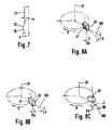
- Figure 8A, 8B and 8C where the longitudinal axis 97 of the tool is taken as a reference and the direction of rotation of the tool is shown by arrow-headed line R, and a radius of the tool, perpendicular to axis 97, is shown by line 100.
- element 20 has a leading face 41 arranged to be inclined downwardly and rearwardly with respect to the direction of rotation R and in relation to the longitudinal axis 97 to create a negative axial rake angle RA with respect to the plane of the longitudinal axis which angle is in the range 1-20 o and preferably in the range 7-10 o .
- the cutting elements may be provided with a negative radial rake angle RR as shown in Figure 8C which is an angle made by each cutting element having a radial outer edge disposed angularly rearwardly of radius 100 with respect to a radially inner edge of the element 20.
- RR radial rake angle
- Such negative radial rake angle may be in the range 1-10 o and preferably about 5 o .
- the cutting edges have not been shown for clarity.
- each of the cutting elements 20 has a leading cutting face 41 which incorporates the cutting edges 30 and recessed portions 31 and a rear face 42 which abuts the blade, the front and rear surfaces being inclined with respect to one another to provide the front surface 41 with the negative axial rake angle RA.
- the elements 20 are located within slots formed in the leading face 17 of the blade and the slots are of constant depth in both longitudinal and radial directions, the negative axial rake angle being provided by the front and rear surfaces 41, 42 respectively of the cutting element 20 being inclined to one another.
- each cutting element 20 having a square cross-section with a length L and height H of 0.375 inches (9.5mm) and a depth D of 4.8mm, the distance h between each of the cutting edges 30 being 0.094 inches (2.3mm).
- each of the cutting edges 30 has an axial rake angle re in the range 0-40 o , preferably 5-12 o , what is known as land angle is in the range 0-35 o preferably 3-15 o .
- the cutting edge 30 protrudes from the recessed portion by distance d in the range 0.001-0.060 inches (0.025-1.5mm), preferably 0.003-0.015 inches (0.076-0.38mm).
- the recess 31 has a negative rake angle portion 32 and a further, planar, portion 33 extending toward an adjacent cutting edge 30.
- the cutting elements are each made of tungsten carbide having European I.S.O. standard P10 to P60 hardness grade and with a cobalt content in the range 7%-20%, such as HSS grade tungsten carbide of Cutting & Wear Resistant Developments Ltd., Rotherham, England.
- the blades 5 are recessed into their respective slots 4.
- fluid is pumped down the drill string to which the tool 1 is attached so as to activate piston 9 and cam 8 to move the blades 5 pivotally radially outwardly against the bias of spring 10 to a cutting position.
- the tool 1 is then rotated for cutting by the leading surface 41 of the cutting elements to commence.
- the depth d and distance h of the cutting edges 30 in combination with the shape of the recessed portion 31 is arranged to provide a generally c-shaped swarf cutting having a thickness of 0.15 inches to 0.020 inches (0.38mm to .05mm).
- the blade shown in Figure 5A has cutting elements 20 disposed radially and axially adjacent to one another so that the portions of blade 24 between each cutting element are no longer present.
- the cutting elements 20 used are similar to those shown in Figures 4A-4C so that the blades 5 have parallel leading and trailing faces and the negative axial rake angle RA is provided by the inclined front and rear faces 41, 42 respectively of the elements 20.
- the blade shown in Figure 5B has cutting elements 120 with parallel front and rear surfaces 143, 144 respectively so that the leading surface 17 of the blade 5 has a staircase formation on the surface thereof to provide the negative axial rake angle RA.
- the cutting element 120 is again used but the negative axial rake angle RA is provided by inclining the blade 5 relative to the axis 97.
- An embodiment of the cutting elements 120 is shown in Figures 6A-6C.
- cutting edges are described in the examplary embodiment more or fewer cutting edges could be provided in dependence upon individual requirements.
- the cutting elements in the preferred embodiment have a quadrilateral cross section in the direction facing rotation of the tool, other shapes could be used such as triangular or hexagonal.
- the present invention has the advantages that if a cutting edge should become worn then a new cutting edge is immediately exposed and by providing the cutting elements on the leading face of the blade in a staggered (brickwork) fashion so a continuous cutting edge is provided in a radial direction of the blade.
- the cutter of this invention therefore provides sharp cutting edges which are continuously exposed to provide efficient milling, the swarf cuttings (chips) that are cut by the tool are of a consistently small size and shape which results in efficient hole cleaning and as a result the rate of penetration of the tool embodying the cutter is rendered more consistent.
Landscapes
- Engineering & Computer Science (AREA)
- Geology (AREA)
- Mining & Mineral Resources (AREA)
- Life Sciences & Earth Sciences (AREA)
- General Life Sciences & Earth Sciences (AREA)
- Fluid Mechanics (AREA)
- Environmental & Geological Engineering (AREA)
- Physics & Mathematics (AREA)
- Geochemistry & Mineralogy (AREA)
- Mechanical Engineering (AREA)
- Milling Processes (AREA)
- Finish Polishing, Edge Sharpening, And Grinding By Specific Grinding Devices (AREA)
- Shovels (AREA)
- Polishing Bodies And Polishing Tools (AREA)
- Drilling Tools (AREA)
- Auxiliary Devices For Machine Tools (AREA)
Priority Applications (1)
| Application Number | Priority Date | Filing Date | Title |
|---|---|---|---|
| AT90301967T ATE90769T1 (de) | 1989-02-24 | 1990-02-23 | Fraeswerkzeug zur verwendung in bohrloechern und schneidelement dafuer. |
Applications Claiming Priority (2)
| Application Number | Priority Date | Filing Date | Title |
|---|---|---|---|
| GB898904251A GB8904251D0 (en) | 1989-02-24 | 1989-02-24 | Downhole milling tool and cutter therefor |
| GB8904251 | 1989-02-24 |
Publications (2)
| Publication Number | Publication Date |
|---|---|
| EP0385673A1 true EP0385673A1 (fr) | 1990-09-05 |
| EP0385673B1 EP0385673B1 (fr) | 1993-06-16 |
Family
ID=10652255
Family Applications (1)
| Application Number | Title | Priority Date | Filing Date |
|---|---|---|---|
| EP90301967A Expired - Lifetime EP0385673B1 (fr) | 1989-02-24 | 1990-02-23 | Outil de fraisage pour fond de puits et élément de coupe pour cet outil |
Country Status (8)
| Country | Link |
|---|---|
| US (1) | US5070952A (fr) |
| EP (1) | EP0385673B1 (fr) |
| AT (1) | ATE90769T1 (fr) |
| CA (1) | CA2010796C (fr) |
| DE (1) | DE69001917T2 (fr) |
| GB (1) | GB8904251D0 (fr) |
| IE (1) | IE63413B1 (fr) |
| NO (1) | NO179805C (fr) |
Cited By (17)
| Publication number | Priority date | Publication date | Assignee | Title |
|---|---|---|---|---|
| GB2262711A (en) * | 1991-12-27 | 1993-06-30 | Hailey Charles D | Cutter blades for rotary tubing tools |
| WO1995003473A1 (fr) * | 1993-07-22 | 1995-02-02 | Baker Hughes Incorporated | Fraise de fond de trou |
| WO1997011251A1 (fr) * | 1995-09-22 | 1997-03-27 | Weatherford/Lamb, Inc. | Piece coupante rapportee destinee a une fraise de meulage de puits de forage |
| WO1997013053A1 (fr) * | 1995-10-05 | 1997-04-10 | The Red Baron (Oil Tools Rental) Limited | Machine et procede de fraisage de cuvelage |
| RU2201493C2 (ru) * | 2001-05-28 | 2003-03-27 | Открытое акционерное общество "Акционерная нефтяная компания "Башнефть" | Вырезающее устройство |
| RU2381860C1 (ru) * | 2008-09-15 | 2010-02-20 | Федеральное государственное унитарное предприятие "Российский Федеральный ядерный центр - Всероссийский научно-исследовательский институт экспериментальной физики" - ФГУП "РФЯЦ-ВНИИЭФ" | Устройство для резки в канале |
| WO2016137822A1 (fr) * | 2015-02-27 | 2016-09-01 | Schlumberger Technology Corporation | Outil et procédé de fraisage |
| EP3447235A1 (fr) * | 2010-03-15 | 2019-02-27 | Weatherford Technology Holdings, LLC | Fraise de section et procédé d'abandon d'un puits de forage |
| US10415318B2 (en) | 2013-12-06 | 2019-09-17 | Schlumberger Technology Corporation | Expandable reamer |
| US10501995B2 (en) | 2014-07-21 | 2019-12-10 | Schlumberger Technology Corporation | Reamer |
| US10508499B2 (en) | 2014-07-21 | 2019-12-17 | Schlumberger Technology Corporation | Reamer |
| US10519722B2 (en) | 2014-07-21 | 2019-12-31 | Schlumberger Technology Corporation | Reamer |
| US10584538B2 (en) | 2014-07-21 | 2020-03-10 | Schlumberger Technology Corporation | Reamer |
| US10612309B2 (en) | 2014-07-21 | 2020-04-07 | Schlumberger Technology Corporation | Reamer |
| US10704332B2 (en) | 2014-07-21 | 2020-07-07 | Schlumberger Technology Corporation | Downhole rotary cutting tool |
| CN111502582A (zh) * | 2014-06-25 | 2020-08-07 | 斯伦贝谢技术有限公司 | 用于启始切口的切削刀片 |
| US10934787B2 (en) | 2013-10-11 | 2021-03-02 | Weatherford Technology Holdings, Llc | Milling system for abandoning a wellbore |
Families Citing this family (35)
| Publication number | Priority date | Publication date | Assignee | Title |
|---|---|---|---|---|
| GB2295172B (en) * | 1994-11-21 | 1998-08-19 | Red Baron | Improvements in or relating to a milling insert and a milling tool |
| US5667903A (en) * | 1995-05-10 | 1997-09-16 | Dresser Industries, Inc. | Method of hard facing a substrate, and weld rod used in hard facing a substrate |
| US5984005A (en) * | 1995-09-22 | 1999-11-16 | Weatherford/Lamb, Inc. | Wellbore milling inserts and mills |
| US6170576B1 (en) | 1995-09-22 | 2001-01-09 | Weatherford/Lamb, Inc. | Mills for wellbore operations |
| US5908071A (en) * | 1995-09-22 | 1999-06-01 | Weatherford/Lamb, Inc. | Wellbore mills and inserts |
| US7077206B2 (en) * | 1999-12-23 | 2006-07-18 | Re-Entry Technologies, Inc. | Method and apparatus involving an integrated or otherwise combined exit guide and section mill for sidetracking or directional drilling from existing wellbores |
| US7451836B2 (en) * | 2001-08-08 | 2008-11-18 | Smith International, Inc. | Advanced expandable reaming tool |
| AU2003232030A1 (en) * | 2002-04-30 | 2003-11-17 | Iqbal Singh | Spade-type drill bit having helical configuration |
| US20040010946A1 (en) * | 2002-07-16 | 2004-01-22 | Alan Duke | Trenching tooth and method |
| US7036611B2 (en) | 2002-07-30 | 2006-05-02 | Baker Hughes Incorporated | Expandable reamer apparatus for enlarging boreholes while drilling and methods of use |
| US7108064B2 (en) * | 2002-10-10 | 2006-09-19 | Weatherford/Lamb, Inc. | Milling tool insert and method of use |
| AT7804U1 (de) * | 2004-02-11 | 2005-09-26 | Ceratizit Austria Gmbh | Klingenförmiger schneideinsatz und werkzeug für seine verwendung |
| US7954564B2 (en) * | 2008-07-24 | 2011-06-07 | Smith International, Inc. | Placement of cutting elements on secondary cutting structures of drilling tool assemblies |
| US20100108402A1 (en) * | 2008-10-31 | 2010-05-06 | Baker Hughes Incorporated | Downhole cutting tool and method of making |
| US9353589B2 (en) | 2011-01-21 | 2016-05-31 | Smith International, Inc. | Multi-cycle pipe cutter and related methods |
| US9493991B2 (en) | 2012-04-02 | 2016-11-15 | Baker Hughes Incorporated | Cutting structures, tools for use in subterranean boreholes including cutting structures and related methods |
| US9512690B2 (en) * | 2012-12-18 | 2016-12-06 | Smith International, Inc. | Milling cutter having undulating chip breaker |
| BR112015023691B1 (pt) | 2013-03-15 | 2021-10-26 | Schlumberger Technology B.V. | Ferramenta de corte de fundo de poço, método para operar ferramenta de corte de fundo de poço e conjunto de fundo de poço |
| US10267113B2 (en) | 2015-02-12 | 2019-04-23 | Halliburton Energy Services, Inc. | Slickline shredder |
| US10392868B2 (en) | 2015-09-30 | 2019-08-27 | Schlumberger Technology Corporation | Milling wellbore casing |
| GB2563564B (en) * | 2017-04-13 | 2020-09-09 | Weatherford Uk Ltd | Downhole apparatus |
| EP4048856B1 (fr) * | 2019-10-21 | 2025-12-17 | Paul Atkins | Outil de fraisage |
| US11719089B2 (en) | 2020-07-15 | 2023-08-08 | Saudi Arabian Oil Company | Analysis of drilling slurry solids by image processing |
| US11506044B2 (en) | 2020-07-23 | 2022-11-22 | Saudi Arabian Oil Company | Automatic analysis of drill string dynamics |
| US11396789B2 (en) | 2020-07-28 | 2022-07-26 | Saudi Arabian Oil Company | Isolating a wellbore with a wellbore isolation system |
| US11492862B2 (en) | 2020-09-02 | 2022-11-08 | Saudi Arabian Oil Company | Cutting pipes in wellbores using downhole autonomous cutting tools |
| US11867008B2 (en) | 2020-11-05 | 2024-01-09 | Saudi Arabian Oil Company | System and methods for the measurement of drilling mud flow in real-time |
| US11434714B2 (en) | 2021-01-04 | 2022-09-06 | Saudi Arabian Oil Company | Adjustable seal for sealing a fluid flow at a wellhead |
| US11697991B2 (en) | 2021-01-13 | 2023-07-11 | Saudi Arabian Oil Company | Rig sensor testing and calibration |
| US11572752B2 (en) | 2021-02-24 | 2023-02-07 | Saudi Arabian Oil Company | Downhole cable deployment |
| US11727555B2 (en) | 2021-02-25 | 2023-08-15 | Saudi Arabian Oil Company | Rig power system efficiency optimization through image processing |
| US11846151B2 (en) | 2021-03-09 | 2023-12-19 | Saudi Arabian Oil Company | Repairing a cased wellbore |
| US11624265B1 (en) | 2021-11-12 | 2023-04-11 | Saudi Arabian Oil Company | Cutting pipes in wellbores using downhole autonomous jet cutting tools |
| US11867012B2 (en) | 2021-12-06 | 2024-01-09 | Saudi Arabian Oil Company | Gauge cutter and sampler apparatus |
| US12203366B2 (en) | 2023-05-02 | 2025-01-21 | Saudi Arabian Oil Company | Collecting samples from wellbores |
Citations (6)
| Publication number | Priority date | Publication date | Assignee | Title |
|---|---|---|---|---|
| GB660440A (en) * | 1949-07-23 | 1951-11-07 | Charles Benjamin Hoole | Improvements in or relating to carbide-and like tipped tools |
| GB947440A (en) * | 1962-02-09 | 1964-01-22 | Jersey Prod Res Co | Drag bit blade |
| US3145790A (en) * | 1963-06-10 | 1964-08-25 | Jersey Prod Res Co | Drag bit |
| US3419077A (en) * | 1966-11-22 | 1968-12-31 | Sanford Lawrence | Well cutting tool |
| US4710074A (en) * | 1985-12-04 | 1987-12-01 | Smith International, Inc. | Casing mill |
| US4717290A (en) * | 1986-12-17 | 1988-01-05 | Homco International, Inc. | Milling tool |
Family Cites Families (9)
| Publication number | Priority date | Publication date | Assignee | Title |
|---|---|---|---|---|
| US1827511A (en) * | 1929-08-28 | 1931-10-13 | Evans Flexible Reamer Corp | Reamer |
| US2290595A (en) * | 1939-11-01 | 1942-07-21 | L P Kinnear | Rotary drill bit |
| US2859943A (en) * | 1957-01-07 | 1958-11-11 | Chadderdon Jack | Expansible mill for well casings |
| US2846193A (en) * | 1957-01-07 | 1958-08-05 | Chadderdon Jack | Milling cutter for use in oil wells |
| US3106973A (en) * | 1960-09-26 | 1963-10-15 | Christensen Diamond Prod Co | Rotary drill bits |
| US3726351A (en) * | 1971-04-26 | 1973-04-10 | E Williams | Mill tool |
| AT345628B (de) * | 1976-03-04 | 1978-09-25 | Amtel Inc | Zweischneidiges flachbohrmesser |
| SE454331B (sv) * | 1984-03-26 | 1988-04-25 | Santrade Ltd | Verktyg och sker for bearbetning av kompositmaterial |
| US4872520A (en) * | 1987-01-16 | 1989-10-10 | Triton Engineering Services Company | Flat bottom drilling bit with polycrystalline cutters |
-
1989
- 1989-02-24 GB GB898904251A patent/GB8904251D0/en active Pending
- 1989-11-28 US US07/445,823 patent/US5070952A/en not_active Expired - Lifetime
-
1990
- 1990-02-14 IE IE54190A patent/IE63413B1/en not_active IP Right Cessation
- 1990-02-22 NO NO900845A patent/NO179805C/no not_active IP Right Cessation
- 1990-02-23 AT AT90301967T patent/ATE90769T1/de not_active IP Right Cessation
- 1990-02-23 EP EP90301967A patent/EP0385673B1/fr not_active Expired - Lifetime
- 1990-02-23 DE DE90301967T patent/DE69001917T2/de not_active Expired - Lifetime
- 1990-02-23 CA CA002010796A patent/CA2010796C/fr not_active Expired - Lifetime
Patent Citations (6)
| Publication number | Priority date | Publication date | Assignee | Title |
|---|---|---|---|---|
| GB660440A (en) * | 1949-07-23 | 1951-11-07 | Charles Benjamin Hoole | Improvements in or relating to carbide-and like tipped tools |
| GB947440A (en) * | 1962-02-09 | 1964-01-22 | Jersey Prod Res Co | Drag bit blade |
| US3145790A (en) * | 1963-06-10 | 1964-08-25 | Jersey Prod Res Co | Drag bit |
| US3419077A (en) * | 1966-11-22 | 1968-12-31 | Sanford Lawrence | Well cutting tool |
| US4710074A (en) * | 1985-12-04 | 1987-12-01 | Smith International, Inc. | Casing mill |
| US4717290A (en) * | 1986-12-17 | 1988-01-05 | Homco International, Inc. | Milling tool |
Cited By (25)
| Publication number | Priority date | Publication date | Assignee | Title |
|---|---|---|---|---|
| GB2262711A (en) * | 1991-12-27 | 1993-06-30 | Hailey Charles D | Cutter blades for rotary tubing tools |
| GB2262711B (en) * | 1991-12-27 | 1994-12-14 | Hailey Charles D | Cutter blades for rotary tubing tools |
| WO1995003473A1 (fr) * | 1993-07-22 | 1995-02-02 | Baker Hughes Incorporated | Fraise de fond de trou |
| WO1995003474A1 (fr) * | 1993-07-22 | 1995-02-02 | Baker Hughes Incorporated | Outil de meulage de fond de trou |
| WO1997011251A1 (fr) * | 1995-09-22 | 1997-03-27 | Weatherford/Lamb, Inc. | Piece coupante rapportee destinee a une fraise de meulage de puits de forage |
| WO1997013053A1 (fr) * | 1995-10-05 | 1997-04-10 | The Red Baron (Oil Tools Rental) Limited | Machine et procede de fraisage de cuvelage |
| RU2201493C2 (ru) * | 2001-05-28 | 2003-03-27 | Открытое акционерное общество "Акционерная нефтяная компания "Башнефть" | Вырезающее устройство |
| RU2381860C1 (ru) * | 2008-09-15 | 2010-02-20 | Федеральное государственное унитарное предприятие "Российский Федеральный ядерный центр - Всероссийский научно-исследовательский институт экспериментальной физики" - ФГУП "РФЯЦ-ВНИИЭФ" | Устройство для резки в канале |
| AU2018256473B2 (en) * | 2010-03-15 | 2020-08-27 | Weatherford Technology Holdings, Llc | Section mill and method for abandoning a wellbore |
| EP3447235A1 (fr) * | 2010-03-15 | 2019-02-27 | Weatherford Technology Holdings, LLC | Fraise de section et procédé d'abandon d'un puits de forage |
| US11846150B2 (en) | 2010-03-15 | 2023-12-19 | Weatherford Technology Holdings, Llc | Section mill and method for abandoning a wellbore |
| US11274514B2 (en) | 2010-03-15 | 2022-03-15 | Weatherford Technology Holdings, Llc | Section mill and method for abandoning a wellbore |
| US10890042B2 (en) | 2010-03-15 | 2021-01-12 | Weatherford Technology Holdings, Llc | Section mill and method for abandoning a wellbore |
| US10934787B2 (en) | 2013-10-11 | 2021-03-02 | Weatherford Technology Holdings, Llc | Milling system for abandoning a wellbore |
| US10415318B2 (en) | 2013-12-06 | 2019-09-17 | Schlumberger Technology Corporation | Expandable reamer |
| CN111502582A (zh) * | 2014-06-25 | 2020-08-07 | 斯伦贝谢技术有限公司 | 用于启始切口的切削刀片 |
| US10704332B2 (en) | 2014-07-21 | 2020-07-07 | Schlumberger Technology Corporation | Downhole rotary cutting tool |
| US10612309B2 (en) | 2014-07-21 | 2020-04-07 | Schlumberger Technology Corporation | Reamer |
| US10584538B2 (en) | 2014-07-21 | 2020-03-10 | Schlumberger Technology Corporation | Reamer |
| US10519722B2 (en) | 2014-07-21 | 2019-12-31 | Schlumberger Technology Corporation | Reamer |
| US10508499B2 (en) | 2014-07-21 | 2019-12-17 | Schlumberger Technology Corporation | Reamer |
| US10501995B2 (en) | 2014-07-21 | 2019-12-10 | Schlumberger Technology Corporation | Reamer |
| WO2016137822A1 (fr) * | 2015-02-27 | 2016-09-01 | Schlumberger Technology Corporation | Outil et procédé de fraisage |
| US10760364B2 (en) | 2015-02-27 | 2020-09-01 | Schlumberger Technology Corporation | Milling tool and method |
| NO348649B1 (en) * | 2015-02-27 | 2025-04-14 | Schlumberger Technology Corp | Milling Tool and Method |
Also Published As
| Publication number | Publication date |
|---|---|
| NO179805C (no) | 1996-12-18 |
| NO179805B (no) | 1996-09-09 |
| DE69001917T2 (de) | 1993-11-04 |
| IE63413B1 (en) | 1995-04-19 |
| CA2010796C (fr) | 1998-04-14 |
| GB8904251D0 (en) | 1989-04-12 |
| US5070952A (en) | 1991-12-10 |
| EP0385673B1 (fr) | 1993-06-16 |
| CA2010796A1 (fr) | 1990-08-24 |
| DE69001917D1 (de) | 1993-07-22 |
| ATE90769T1 (de) | 1993-07-15 |
| IE900541L (en) | 1990-08-24 |
| NO900845L (no) | 1990-08-27 |
| NO900845D0 (no) | 1990-02-22 |
Similar Documents
| Publication | Publication Date | Title |
|---|---|---|
| EP0385673B1 (fr) | Outil de fraisage pour fond de puits et élément de coupe pour cet outil | |
| US3955635A (en) | Percussion drill bit | |
| EP0285678A1 (fr) | Trépan de forage pour formations dures et tendres | |
| AU642075B2 (en) | Rotary drill bit insert | |
| US3860354A (en) | Annular hole cutter | |
| GB2318371A (en) | Carrier-mounted cutting element and chip breaker for drill bit | |
| CN1270882A (zh) | 岩钻 | |
| USRE28416E (en) | Annular hole cutter | |
| CA2287361C (fr) | Organe annulaire de percage | |
| EP0028602B1 (fr) | Outil de coupe | |
| US5143163A (en) | Digging tooth | |
| US5476149A (en) | Pilot bit | |
| AU5278990A (en) | An excavating tooth for an earth auger | |
| US5067262A (en) | Digging tooth | |
| GB2280692A (en) | A milling insert and milling tool | |
| US6796751B2 (en) | Serrated ball nose end mill insert | |
| GB2270097A (en) | Cutting element for use on a mill | |
| CN112139571A (zh) | 加强合金刀头麻花钻 | |
| CN111065479A (zh) | 钻孔刀片 | |
| EP0341073A1 (fr) | Lame pour outil de découpage de tubes et procédé pour son montage | |
| EP0119620B1 (fr) | Type de dent comportant l'utilisation d'éléments de coupe diamantés cylindriques | |
| RU2047724C1 (ru) | Резец для вращательного бурения | |
| JPH0321851Y2 (fr) | ||
| KR100592543B1 (ko) | 드릴 비트 | |
| CN220127673U (zh) | 一种硬质合金划刀 |
Legal Events
| Date | Code | Title | Description |
|---|---|---|---|
| PUAI | Public reference made under article 153(3) epc to a published international application that has entered the european phase |
Free format text: ORIGINAL CODE: 0009012 |
|
| AK | Designated contracting states |
Kind code of ref document: A1 Designated state(s): AT DE DK ES FR GB GR IT NL |
|
| 17P | Request for examination filed |
Effective date: 19910305 |
|
| 17Q | First examination report despatched |
Effective date: 19910904 |
|
| GRAA | (expected) grant |
Free format text: ORIGINAL CODE: 0009210 |
|
| AK | Designated contracting states |
Kind code of ref document: B1 Designated state(s): AT DE DK ES FR GB GR IT NL |
|
| PG25 | Lapsed in a contracting state [announced via postgrant information from national office to epo] |
Ref country code: DK Effective date: 19930616 Ref country code: NL Effective date: 19930616 Ref country code: GR Free format text: LAPSE BECAUSE OF FAILURE TO SUBMIT A TRANSLATION OF THE DESCRIPTION OR TO PAY THE FEE WITHIN THE PRESCRIBED TIME-LIMIT Effective date: 19930616 Ref country code: ES Free format text: THE PATENT HAS BEEN ANNULLED BY A DECISION OF A NATIONAL AUTHORITY Effective date: 19930616 |
|
| REF | Corresponds to: |
Ref document number: 90769 Country of ref document: AT Date of ref document: 19930715 Kind code of ref document: T |
|
| REF | Corresponds to: |
Ref document number: 69001917 Country of ref document: DE Date of ref document: 19930722 |
|
| ET | Fr: translation filed | ||
| ITF | It: translation for a ep patent filed | ||
| K2C2 | Correction of patent specification (partial reprint) published |
Effective date: 19930616 |
|
| NLV1 | Nl: lapsed or annulled due to failure to fulfill the requirements of art. 29p and 29m of the patents act | ||
| PLBI | Opposition filed |
Free format text: ORIGINAL CODE: 0009260 |
|
| 26 | Opposition filed |
Opponent name: THE RED BARON (OIL TOOLS RENTAL) LIMITED Effective date: 19940316 |
|
| REG | Reference to a national code |
Ref country code: GB Ref legal event code: 732E |
|
| PLAB | Opposition data, opponent's data or that of the opponent's representative modified |
Free format text: ORIGINAL CODE: 0009299OPPO |
|
| R26 | Opposition filed (corrected) |
Opponent name: THE RED BARON (OIL TOOLS RENTAL) LIMITED Effective date: 19940316 |
|
| PLBL | Opposition procedure terminated |
Free format text: ORIGINAL CODE: EPIDOS OPPC |
|
| PLBM | Termination of opposition procedure: date of legal effect published |
Free format text: ORIGINAL CODE: 0009276 |
|
| STAA | Information on the status of an ep patent application or granted ep patent |
Free format text: STATUS: OPPOSITION PROCEDURE CLOSED |
|
| 27C | Opposition proceedings terminated |
Effective date: 19960617 |
|
| REG | Reference to a national code |
Ref country code: GB Ref legal event code: 727 |
|
| REG | Reference to a national code |
Ref country code: GB Ref legal event code: 727A |
|
| REG | Reference to a national code |
Ref country code: GB Ref legal event code: 727B |
|
| REG | Reference to a national code |
Ref country code: GB Ref legal event code: SP |
|
| REG | Reference to a national code |
Ref country code: GB Ref legal event code: IF02 |
|
| PGFP | Annual fee paid to national office [announced via postgrant information from national office to epo] |
Ref country code: AT Payment date: 20090203 Year of fee payment: 20 |
|
| PGFP | Annual fee paid to national office [announced via postgrant information from national office to epo] |
Ref country code: GB Payment date: 20090227 Year of fee payment: 20 |
|
| PG25 | Lapsed in a contracting state [announced via postgrant information from national office to epo] |
Ref country code: IT Free format text: LAPSE BECAUSE OF NON-PAYMENT OF DUE FEES Effective date: 20080223 |
|
| PGFP | Annual fee paid to national office [announced via postgrant information from national office to epo] |
Ref country code: DE Payment date: 20090331 Year of fee payment: 20 Ref country code: IT Payment date: 20090226 Year of fee payment: 19 |
|
| PGFP | Annual fee paid to national office [announced via postgrant information from national office to epo] |
Ref country code: FR Payment date: 20090217 Year of fee payment: 20 |
|
| REG | Reference to a national code |
Ref country code: GB Ref legal event code: PE20 Expiry date: 20100222 |
|
| PG25 | Lapsed in a contracting state [announced via postgrant information from national office to epo] |
Ref country code: GB Free format text: LAPSE BECAUSE OF EXPIRATION OF PROTECTION Effective date: 20100222 |
|
| PG25 | Lapsed in a contracting state [announced via postgrant information from national office to epo] |
Ref country code: DE Free format text: LAPSE BECAUSE OF EXPIRATION OF PROTECTION Effective date: 20100223 |