EP0385681A2 - Chaîne pour une transmission de puissance - Google Patents
Chaîne pour une transmission de puissance Download PDFInfo
- Publication number
- EP0385681A2 EP0385681A2 EP19900301994 EP90301994A EP0385681A2 EP 0385681 A2 EP0385681 A2 EP 0385681A2 EP 19900301994 EP19900301994 EP 19900301994 EP 90301994 A EP90301994 A EP 90301994A EP 0385681 A2 EP0385681 A2 EP 0385681A2
- Authority
- EP
- European Patent Office
- Prior art keywords
- links
- link
- toes
- guide
- plain
- Prior art date
- Legal status (The legal status is an assumption and is not a legal conclusion. Google has not performed a legal analysis and makes no representation as to the accuracy of the status listed.)
- Granted
Links
- 230000005540 biological transmission Effects 0.000 title claims abstract description 54
- 210000003371 toe Anatomy 0.000 claims abstract description 131
- 238000009826 distribution Methods 0.000 claims abstract description 10
- 230000002093 peripheral effect Effects 0.000 claims description 6
- 210000003734 kidney Anatomy 0.000 claims description 4
- 239000000463 material Substances 0.000 claims description 4
- 238000001228 spectrum Methods 0.000 claims description 4
- 238000004519 manufacturing process Methods 0.000 claims description 2
- 210000001255 hallux Anatomy 0.000 claims 4
- 210000000453 second toe Anatomy 0.000 claims 4
- 238000000034 method Methods 0.000 claims 2
- 239000011295 pitch Substances 0.000 description 23
- 208000029321 non-syndromic brachydactyly of toes Diseases 0.000 description 6
- 238000005452 bending Methods 0.000 description 2
- 239000004576 sand Substances 0.000 description 2
- 230000003068 static effect Effects 0.000 description 2
- 235000008331 Pinus X rigitaeda Nutrition 0.000 description 1
- 235000011613 Pinus brutia Nutrition 0.000 description 1
- 241000018646 Pinus brutia Species 0.000 description 1
- 230000000052 comparative effect Effects 0.000 description 1
- 230000000295 complement effect Effects 0.000 description 1
- 230000006835 compression Effects 0.000 description 1
- 238000007906 compression Methods 0.000 description 1
- 230000000115 debilitative effect Effects 0.000 description 1
- 230000007423 decrease Effects 0.000 description 1
- 230000003247 decreasing effect Effects 0.000 description 1
- 230000000694 effects Effects 0.000 description 1
- 230000005489 elastic deformation Effects 0.000 description 1
- 230000001747 exhibiting effect Effects 0.000 description 1
- 210000003414 extremity Anatomy 0.000 description 1
- 238000012986 modification Methods 0.000 description 1
- 230000004048 modification Effects 0.000 description 1
- 230000000737 periodic effect Effects 0.000 description 1
- 239000007787 solid Substances 0.000 description 1
Images

Classifications
-
- F—MECHANICAL ENGINEERING; LIGHTING; HEATING; WEAPONS; BLASTING
- F16—ENGINEERING ELEMENTS AND UNITS; GENERAL MEASURES FOR PRODUCING AND MAINTAINING EFFECTIVE FUNCTIONING OF MACHINES OR INSTALLATIONS; THERMAL INSULATION IN GENERAL
- F16G—BELTS, CABLES, OR ROPES, PREDOMINANTLY USED FOR DRIVING PURPOSES; CHAINS; FITTINGS PREDOMINANTLY USED THEREFOR
- F16G13/00—Chains
- F16G13/02—Driving-chains
- F16G13/04—Toothed chains
Definitions
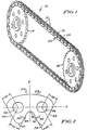
- a power transmission chain in an automotive application is illustrated by a vehicle engine and an automatic transmission disposed in a parallel relationship.
- a chain and sprocket drive arrangement connects a hydrodynamic torque converter output shaft of the engine to the transmission power input shaft.
- the transmission drives the vehicle wheels through an output shaft, gears, and a cross shaft.
- the chain and sprocket drive apparatus tranduces power from the engine to the wheels.
- the endless chains are assembled from a series of interconnected link plates having tooth portions that mesh with the teeth of the sprocket wheels.
- the silent chain used in automotive chain drives is assembled from several links positioned along side of or adjacent to each other to form a set or rank of links.
- a plurality of sets or ranks of links are interleaved with one another and secured by pine to construct a series of connected ranks and build an endless chain of any desired length.
- the links of a silent chain each have a pair of toes, separated by a crotch. Each toe is defined by outside and inside flanks. The inside flanks define the crotch.
- the chain includes rows of links that have disposed on a transverse pin a guide link at each outer end maintaining therebetween the links of a rank.
- These two guide links serve to connect the pins of adjacent rows and also act to track the chain over the sprockets during movement of the chain therearound.
- guide links are structurally more rigid than the remaining plain links of the same rank or row.
- a guide link row thus comprises links of varying physical characteristics; i.e., plain links whose teeth engage the teeth of the sprockets and more rigid, non-sprocket engaging guide links that hold the chain together during operation thereof.
- Another object of the present invention is to provide a power transmission drive chain having a plurality of links disposed in ranks of the chain that cooperate to balance load distribution between ranks and maintain transverse connecting pins substantially parallel to each other.
- a further object of this invention is to provide a power transmission chain having a plurality of plain links having two toes which however are not the same; one toe being overall smaller than the other toe of the same link, and placing or arranging within the chain, the differently sized toes in a manner such that the timing interval between successive sprocket tooth contacts either increases or decreases from a nominal value depending upon whether a short or small toe follows a large toe or a large toe follows a short or small toe.
- a power transmission chain constructed in accordance with the present invention comprises a plurality of plain links arranged in side by side relationship to form plurality of ranks of links, each of the plain links having apertures formed therethrough to receive a pin and having two dissimilar sprocket engaging toes, one characterized as a large toe and the other as the small toe, a plurality of guide links having apertures formed therethrough to receive a pin, the guide links being mounted on distal ends of pins connecting first alternate ranks of plain links so as to form a guide link row, the other alternate ranks of plain links being effective to form an articulated link row, a plurality of guide link rows and a plurality of articulated link rows being interweaved and interconnected by the pins to form the chain, the plurality of plain links in each guide link row being disposed between the guide links, the plurality of guide links in each guide link row each being equal in thickness and having a configuration that avoids any peripheral discontinuity, whereby when the chain is subjected to a load, the configuration and the
- a power transmission chain is constructed of transversely aligned sets of links joined together in a continuous assembly, each link of each set having the same shape with a pair of toes each defined by diverging outside and inside flanks, the toes being separated by a crotch; one toe of each link being different in configuration from the other toe of each link with the different shaped toes in each set being transversely aligned; and some sets of links being flip-flopped in said continuous assembly so that said different toes are leading toes while in the remainder of said sets of links said different toes are trailing toes.
- Each set or rank 18 of the chain 12 may comprise a plurality of plain links 20 as depicted in FIG. 2.
- the link 20 is formed in two sizes, a first size having a thickness A and a second size having a thickness B, both as shown in FIG. 5.
- a link 20 having a thickness A is dimensionally thicker than a link 20 having a thickness B.
- a link 20 having a thickness A is intended to be placed along with other identical links in a rank 18 identified generally as an articulated pitch 24 as shown in FIGS. 1, 7, and 8.
- a link 20 having a thickness B is intended to be placed along with other identical links in an adjacent or successive rank 18 identified generally as a guide row pitch 26 as shown in FIGS. 1, 7, and 8.
- each link indicated generally by the arrow 20 includes a top or back side 28, a bottom part comprising two unequal length, dissimilarly shaped teeth or toes 30 and 32 and two apertures 34 and 36 disposed substantially vertically above each toe formed on the bottom side of the link.
- each link 20 will be considered to have a horizontal, longitudinal axis that extends through and connects the centers of each aperture 34 and 36 or pin hole and divides the link into an upper and a lower portion.
- the upper portion of the link extends generally above the horizontal axis and is termed a generally arcuate back side of the link.
- the lower portion of the link extends generally below the horizontal axis, is termed the toe or tooth side of the link and may be described as asymmetrical in shape.
- each link is considered to have a vertical, central axis that bisects equally the distance between the centers of the pin holes and divides each link into a left hand and a right hand side.
- each link 20 includes a respective arcuate upper or back portion 28 extending generally above the longitudinal center line connecting the centers of the pitch holes and a respective lower or tooth portion extending downwardly from the longitudnal center line of the link forming the two downwardly extending dissimilar toes or teeth 30 and 32.
- the two toes 30, 32 of each link have their respective outer working surfaces or flanks 40 and 42 formed to provide relatively straight surfaces sloping inwardly or toward the vertical central axis y that divides substantially equally the distance between the centers of the pin holes 34 and 36.
- each toe 30 and 32 are shaped in the form of curved or arcuate flanks 44 and 46 or they can also be straight. These surfaces begin at the lower most extremity of each toe and extend inwardly and upwardly toward the middle portion of each link to meet and form a crotch portion 48 thereat.
- the toes 30 and 32 of link 20 have differently shaped configurations. Even though the inner surfaces 44 and 46 of toes 30 and 32 are both arcuate in shape, and are both formed by substantially equal radii 50, the center point of each respective radius 50 is located at different remote locations respectively (not shown) in the first and second quadrants and therefore establish different distances between the inner surface 44 and the center of aperture 34 and the inner surface 46 and the center of aperture 36. For example, the distance 62 from the center of the pin of aperture 36 to inner working surface 46 is greater than the distance 64 from the center of aperture 35 to working surface 44. Additionally, the length of toe 30 is shortened so as to maintain a reasonable radius of curvature at the tip of the tooth or toe.
- a guide link 52 having a configuration substantially kidney shaped in profile disposed about a horizontal axis x and a vertical axis y that together serve to divide the guide link into four quadrants.
- the link 52 has disposed at equal distances outwardly from the vertical axis y a pair of apertures 54.
- the apertures 54 have their respective centers located along and coincide with the horizontal axis x.
- the link 52 is formed having a bottom edge or surface 56 that extends essentially horizontally, but may be slightly curved, for a preselected distance on either side of axis y and then is caused to generate by a bottom radius 58 in a first curvilinear direction upwardly to and somewhat beyond the x axis.
- the surface diverges upwardly and inwardly for a preselected distance, then is caused to bend radially, and thereafter generates downwardly and inwardly to form an upwardly extending toe.
- a surface from the other side of the link is generated upwardly and inwardly, rounded off, thereafter extended downwardly and inwardly to form another toe.
- the two toes form therebetween a concave portion or crotch 60. It will be understood that the two toes of the guide link 52 are similar to the toes of a plain link 20, but are of a lesser length or height.
- each guide link 52 having a homogeneous, continuous profile is designed to deform under load in a predetermined, predictable mode of operation without incurring substantial stress raisers.
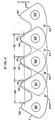
- the chain 12 as shown in a typical multiple row segment of ranks 18 comprises an articulated pitch 24A including a set of plain links 20 assembled with the short toe 30 in the leading position assuming the chain moves from left to right.
- the sets of links 20 in articulated pitches 24 and 24A are formed from an A dimension thickness.
- the segment of ranks 18 includes a guide pitch 26 comprising plain links 20 assembled also with the short toe 30 in the leading position.
- the sets of plain links 20 in guide pitch 26 are formed from a B dimension thickness.
- a tangent to the inside flank surface of the longer toe is located at a different distance from the center of the nearest opening thereto than a tangent to the inside flank of the other toe from the center of the nearest opening thereto or the other opening in the link body.
- the perpendicular distance from the center of a nearest pin hole opening to the tangent of the inside flank of the longer toe is greater than the perpendicular distance from the center of the nearest pin hole opening to the tangent of the inside flank of the shorter toe.
- a plurality of links 20 having thickness A are arranged side by side or transversely to form a set or rank 18 for an articulated pitch 24.
- a plurality of links 20 having thickness B are similarly arranged side by side to form a set or rank 18 for a guide pitch 26.
- the set 18 of the articulated pitch 24 and the set 18 of the guide pitch 26 are then arranged in tandem so that the ends of the links of the articulated pitch 24 are interlaced with the adjacent ends of the links of guide pitch 26 and a pin 38 is then inserted to extend through the holes 34, 36 of the interlaced sets of links to form a pivotal connection therebetween.
- guide links 52 are disposed at distal ends of the pins 38 on the outer sides of the plain link sets at selected portions along the length of the chain.
- the guide links 52 serve to connect the articulating link rows and provide structural rigidity throughout the chain.
- a first guide rank could include a grouping of links having a B thickness and a certain toe orientation i.e., short toe either leading or trailing.
- Each successive guide rank could include a grouping of links having a B thickness and either the same toe orientation or the reversed toe orientation.
Landscapes
- Engineering & Computer Science (AREA)
- General Engineering & Computer Science (AREA)
- Mechanical Engineering (AREA)
- Devices For Conveying Motion By Means Of Endless Flexible Members (AREA)
- Transmissions By Endless Flexible Members (AREA)
- Retarders (AREA)
Applications Claiming Priority (2)
| Application Number | Priority Date | Filing Date | Title |
|---|---|---|---|
| US07316776 US4915675B1 (en) | 1989-02-28 | 1989-02-28 | Pitch equalized chain with frequency modulated engagement |
| US316776 | 1989-02-28 |
Publications (3)
| Publication Number | Publication Date |
|---|---|
| EP0385681A2 true EP0385681A2 (fr) | 1990-09-05 |
| EP0385681A3 EP0385681A3 (fr) | 1991-09-18 |
| EP0385681B1 EP0385681B1 (fr) | 1995-10-18 |
Family
ID=23230638
Family Applications (1)
| Application Number | Title | Priority Date | Filing Date |
|---|---|---|---|
| EP90301994A Expired - Lifetime EP0385681B1 (fr) | 1989-02-28 | 1990-02-26 | Chaîne pour une transmission de puissance |
Country Status (6)
| Country | Link |
|---|---|
| US (1) | US4915675B1 (fr) |
| EP (1) | EP0385681B1 (fr) |
| JP (1) | JPH02278040A (fr) |
| CA (1) | CA2010910C (fr) |
| DE (1) | DE69023021T2 (fr) |
| ES (1) | ES2080790T3 (fr) |
Cited By (1)
| Publication number | Priority date | Publication date | Assignee | Title |
|---|---|---|---|---|
| GB2360342A (en) * | 2000-03-15 | 2001-09-19 | Tsubakimoto Chain Co | Low noise silent chain |
Families Citing this family (55)
| Publication number | Priority date | Publication date | Assignee | Title |
|---|---|---|---|---|
| US5263903A (en) * | 1990-03-20 | 1993-11-23 | Borg-Warner Automotive Transmission & Engine Components Corporation | Chain-belt |
| US5090948A (en) * | 1990-03-20 | 1992-02-25 | Borg-Warner Automotive Transmission & Engine Components Corporation | Chain belt power transmission |
| US5154674A (en) * | 1990-04-25 | 1992-10-13 | Borg-Warner Automotive Transmission & Engine Components Corporation | Power transmission chain constructed with asymmetrical links |
| JPH0444543U (fr) * | 1990-08-20 | 1992-04-15 | ||
| JPH068357Y2 (ja) * | 1990-09-13 | 1994-03-02 | 株式会社椿本チエイン | サイレントチェーン |
| JPH081312Y2 (ja) * | 1992-03-30 | 1996-01-17 | 株式会社椿本チエイン | 低騒音サイレントチェ−ン |
| US5453059A (en) * | 1992-05-19 | 1995-09-26 | Borg-Warner Automotive, Inc. | Variable pitch silent chain |
| US5397280A (en) * | 1993-10-04 | 1995-03-14 | Borg-Warner Automotive, Inc. | System phasing of overhead cam engine timing chains |
| US5427580A (en) * | 1992-05-19 | 1995-06-27 | Borg-Warner Automotive, Inc. | Phased chain assemblies |
| US5345753A (en) * | 1993-07-28 | 1994-09-13 | Borg-Warner Automotive, K.K. | Silent chain |
| DE4330696C1 (de) * | 1993-09-10 | 1995-03-30 | Piv Antrieb Reimers Kg Werner | Laschenkette für stufenlos verstellbare Kegelscheibengetriebe |
| US5445570A (en) * | 1994-02-15 | 1995-08-29 | Borg-Warner Automotive, Inc. | Chain guide link |
| US5464374A (en) * | 1994-08-03 | 1995-11-07 | Borg-Warner Automotive, Inc. | Chain having improved load distribution |
| JPH0874940A (ja) * | 1994-09-02 | 1996-03-19 | Borg Warner Automot Kk | 動力伝達用チェーン |
| US5588926A (en) * | 1995-04-20 | 1996-12-31 | Borg-Warner Automotive, Inc. | Self-guided chain assemblies |
| US5876295A (en) * | 1996-01-23 | 1999-03-02 | Cloyes Gear And Products, Inc. | Roller chain drive system having improved noise characteristics |
| JP3035206B2 (ja) * | 1996-01-24 | 2000-04-24 | 株式会社椿本チエイン | サイレントチェーン |
| JP3075986B2 (ja) * | 1996-06-13 | 2000-08-14 | 株式会社椿本チエイン | サイレントチェーンのプレート |
| US5921878A (en) * | 1996-07-03 | 1999-07-13 | Cloyes Gear And Products, Inc. | Roller chain drive system having improved noise characteristics |
| US6090003A (en) * | 1996-07-25 | 2000-07-18 | Cloyes Gear & Products, Inc. | Random engagement roller chain sprocket having improved noise characteristics |
| US5921879A (en) | 1996-07-25 | 1999-07-13 | Cloyes Gear And Products, Inc. | Random engagement roller chain sprocket with staged meshing and flank relief to provide improved noise characteristics |
| WO1998004848A2 (fr) * | 1996-07-25 | 1998-02-05 | Cloyes Gear And Products, Inc. | Roue dentee pour chaines a rouleaux a engagement aleatoire ayant une caracteristique bruit amelioree |
| US5758484A (en) * | 1996-09-30 | 1998-06-02 | Borg-Warner Automotive, Inc. | Silent chain with raised link backs |
| US6761657B2 (en) | 1996-12-19 | 2004-07-13 | Cloyes Gear And Products, Inc. | Roller chain sprocket with added chordal pitch reduction |
| US7416500B2 (en) * | 1996-12-19 | 2008-08-26 | Cloyes Gear And Products, Inc. | Random engagement roller chain sprocket and timing chain system including same |
| JP3420696B2 (ja) | 1997-12-29 | 2003-06-30 | ボルグワーナー・モールステック・ジャパン株式会社 | サイレントチェーン伝動装置 |
| US6186920B1 (en) | 1998-02-10 | 2001-02-13 | Cloyes Gear And Products, Inc. | Short pitch tooth chain |
| JP3096274B2 (ja) * | 1998-06-30 | 2000-10-10 | 株式会社椿本チエイン | サイレントチェーン |
| HUP0204184A2 (en) | 1998-07-04 | 2003-03-28 | Renold Plc | A chain |
| JP2000065155A (ja) * | 1998-08-21 | 2000-03-03 | Honda Motor Co Ltd | サイレントチェーン |
| US6364800B1 (en) | 1998-09-21 | 2002-04-02 | Borgwarner Inc. | Interior guided chain system for lateral chain control |
| US6387001B1 (en) | 2000-01-21 | 2002-05-14 | Borgwarner Inc. | Rollerless chain having sprocket-engaging pins |
| JP2003166600A (ja) * | 2001-11-30 | 2003-06-13 | Tsubakimoto Chain Co | サイレントチェーン |
| JP3589650B2 (ja) * | 2001-12-20 | 2004-11-17 | 株式会社椿本チエイン | サイレントチェーン伝動機構 |
| AU2003234487A1 (en) * | 2002-05-06 | 2003-11-11 | Cloyes Gear And Products, Inc. | Cushioned sprocket and improved inverted tooth chain for use with same |
| JP2004116632A (ja) * | 2002-09-25 | 2004-04-15 | Shigeyoshi Osada | サイレントチェーン伝動装置 |
| JP4530640B2 (ja) * | 2002-10-24 | 2010-08-25 | ボルグワーナー・モールステック・ジャパン株式会社 | サイレントチェーンおよびその製造方法 |
| JP2004169747A (ja) * | 2002-11-18 | 2004-06-17 | Borg Warner Morse Tec Japan Kk | サイレントチェーン |
| JP2004183851A (ja) * | 2002-12-06 | 2004-07-02 | Borg Warner Morse Tec Japan Kk | サイレントチェーン |
| WO2006036603A1 (fr) * | 2004-09-24 | 2006-04-06 | Cloyes Gear And Products, Inc. | Systeme de chaine a dents inversees avec engrenement sur flanc interieur |
| US7803080B2 (en) * | 2005-12-13 | 2010-09-28 | Borgwarner Inc. | High strength and stiffness silent chain with improved noise |
| JP5160096B2 (ja) * | 2007-01-31 | 2013-03-13 | 株式会社ジェイテクト | 動力伝達チェーンおよびこれを備える動力伝達装置 |
| JP4420946B2 (ja) * | 2007-08-03 | 2010-02-24 | 株式会社椿本チエイン | 両面噛合い型サイレントチェーン |
| JP5340670B2 (ja) * | 2008-08-22 | 2013-11-13 | 株式会社椿本チエイン | 昇降駆動用噛合多列チェーン |
| US8672786B2 (en) * | 2008-09-09 | 2014-03-18 | Cloyes Gear And Products, Inc. | Inverted tooth chain and sprocket drive system with reduced meshing impact |
| US9377082B2 (en) | 2008-09-09 | 2016-06-28 | Cloyes Gear And Products, Inc. | Inverted tooth chain and sprocket drive system with reduced meshing impact |
| US8529389B2 (en) * | 2008-09-09 | 2013-09-10 | Cloyes Gear And Products, Inc. | Inverted tooth chain and sprocket drive system with reduced meshing impact |
| US8628440B2 (en) | 2008-09-09 | 2014-01-14 | Cloyes Gear And Products, Inc. | Inverted tooth chain and sprocket drive system with reduced meshing impact |
| JP5251634B2 (ja) * | 2009-03-13 | 2013-07-31 | 日産自動車株式会社 | チェーン |
| JP4846825B2 (ja) * | 2009-05-28 | 2011-12-28 | 株式会社椿本チエイン | 低干渉音型サイレントチェーン |
| DE102009053597A1 (de) | 2009-11-17 | 2011-05-19 | Schaeffler Technologies Gmbh & Co. Kg | Kette für einen Steuerantrieb oder einen Aggregatantrieb einer Antriebseinrichtung eines Kraftfahrzeuges |
| US8766507B2 (en) * | 2010-02-10 | 2014-07-01 | Mando Corporation | Motor pulley |
| DE112015003844T5 (de) * | 2014-08-22 | 2017-07-27 | Schaeffler Technologies AG & Co. KG | Hochfeste umgekehrte Zahnradkette mit einer durch einen Presssitz montierten Mittelplatte |
| DE102017116245A1 (de) | 2017-07-19 | 2019-01-24 | Schaeffler Technologies AG & Co. KG | Kette eines Kettentriebs, die über Mittellaschen geführt ist |
| USD998059S1 (en) * | 2021-07-14 | 2023-09-05 | Jinfeng Cai | Marble run toy |
Family Cites Families (15)
| Publication number | Priority date | Publication date | Assignee | Title |
|---|---|---|---|---|
| DE126589C (fr) * | ||||
| US16521A (en) * | 1857-02-03 | beardsley | ||
| DE209710C (fr) * | ||||
| US1138236A (en) * | 1908-12-15 | 1915-05-04 | Morse Chain Co | Multiplate drive-chain. |
| FR411861A (fr) * | 1910-01-19 | 1910-06-28 | James Mapes Dodge | Perfectionnements apportés aux chaines |
| US1463789A (en) * | 1920-05-22 | 1923-08-07 | Edward I Braddock | Gear chain |
| US1578271A (en) * | 1924-01-30 | 1926-03-30 | Link Belt Co | Noiseless chain |
| US1868334A (en) * | 1929-03-21 | 1932-07-19 | Morse Chain Co | Drive chain |
| US3377875A (en) * | 1966-05-09 | 1968-04-16 | Gen Motors Corp | Chain drive power transmitting mechanism |
| US3495468A (en) * | 1968-11-21 | 1970-02-17 | Gen Motors Corp | Chain drive |
| US4168634A (en) * | 1977-05-27 | 1979-09-25 | General Motors Corporation | Chain and sprocket power transmitting mechanism |
| US4342560A (en) * | 1980-05-16 | 1982-08-03 | Borg-Warner Corporation | Composite chain link assembly |
| EP0092900A2 (fr) * | 1982-04-23 | 1983-11-02 | Borg-Warner Corporation | Chaîne de transmission perfectionnée |
| DE3578549D1 (de) * | 1984-10-17 | 1990-08-09 | Borg Warner Automotive | Treibkette. |
| US4906224A (en) * | 1989-02-22 | 1990-03-06 | Magna International, Inc. | Inverted tooth chain |
-
1989
- 1989-02-28 US US07316776 patent/US4915675B1/en not_active Expired - Lifetime
-
1990
- 1990-02-26 DE DE69023021T patent/DE69023021T2/de not_active Expired - Fee Related
- 1990-02-26 CA CA002010910A patent/CA2010910C/fr not_active Expired - Fee Related
- 1990-02-26 ES ES90301994T patent/ES2080790T3/es not_active Expired - Lifetime
- 1990-02-26 EP EP90301994A patent/EP0385681B1/fr not_active Expired - Lifetime
- 1990-02-28 JP JP2045980A patent/JPH02278040A/ja active Pending
Cited By (3)
| Publication number | Priority date | Publication date | Assignee | Title |
|---|---|---|---|---|
| GB2360342A (en) * | 2000-03-15 | 2001-09-19 | Tsubakimoto Chain Co | Low noise silent chain |
| US6533691B2 (en) | 2000-03-15 | 2003-03-18 | Tsubakimoto Chain Co. | Low noise silent chain |
| GB2360342B (en) * | 2000-03-15 | 2004-03-10 | Tsubakimoto Chain Co | Low noise silent chain |
Also Published As
| Publication number | Publication date |
|---|---|
| EP0385681B1 (fr) | 1995-10-18 |
| JPH02278040A (ja) | 1990-11-14 |
| DE69023021D1 (de) | 1995-11-23 |
| DE69023021T2 (de) | 1996-03-21 |
| CA2010910A1 (fr) | 1990-08-31 |
| CA2010910C (fr) | 1999-08-10 |
| EP0385681A3 (fr) | 1991-09-18 |
| US4915675A (en) | 1990-04-10 |
| ES2080790T3 (es) | 1996-02-16 |
| US4915675B1 (en) | 1998-12-29 |
Similar Documents
| Publication | Publication Date | Title |
|---|---|---|
| US4915675A (en) | Pitch equalized chain with frequency modulated engagement | |
| US5453059A (en) | Variable pitch silent chain | |
| US5445570A (en) | Chain guide link | |
| US4650445A (en) | Chain-belt | |
| US5372554A (en) | Rocker joint chain with crescent shaped apertures | |
| US7094170B2 (en) | Cushioned sprocket and improved inverted tooth chain for use with same | |
| EP1277987B1 (fr) | Chaîne pour transmission de puissance avec plaquettes de guidages alternées | |
| US5551925A (en) | Chain assemblies with minimal pin projection | |
| JPH0351933B2 (fr) | ||
| US4386922A (en) | Power transmission chain belt | |
| US5226856A (en) | Roller chain constructed with nylon rollers | |
| US6168543B1 (en) | Silent chain and sprocket having teeth with matching curved surfaces | |
| US5507697A (en) | Minimal pin projection roller chain | |
| JP3463942B2 (ja) | チエーン組立体 | |
| US5588926A (en) | Self-guided chain assemblies | |
| US5562559A (en) | Rocker joint chain with crescent shaped aperture | |
| US20020058561A1 (en) | Silent chain | |
| US5435789A (en) | Inverted tooth chain constructed with links having a single toe | |
| US5857933A (en) | Chain assembly with flat links of extended horizontal length | |
| GB2190169A (en) | Power transmission belt | |
| EP0139472B1 (fr) | Chaîne de transmission et maillon correspondant | |
| US6939260B2 (en) | Silent drive chain assembly having flexible links | |
| EP0178818B1 (fr) | Chaîne de transmission | |
| US4579550A (en) | Chains for continuously variable conical pulley transmissions | |
| EP0092900A2 (fr) | Chaîne de transmission perfectionnée |
Legal Events
| Date | Code | Title | Description |
|---|---|---|---|
| PUAI | Public reference made under article 153(3) epc to a published international application that has entered the european phase |
Free format text: ORIGINAL CODE: 0009012 |
|
| AK | Designated contracting states |
Kind code of ref document: A2 Designated state(s): DE ES FR GB IT NL SE |
|
| DIN1 | Information on inventor provided before grant (deleted) | ||
| RAP1 | Party data changed (applicant data changed or rights of an application transferred) |
Owner name: BORG-WARNER AUTOMOTIVE TRANSMISSION AND ENGINE COM |
|
| RIN1 | Information on inventor provided before grant (corrected) |
Inventor name: AVRAMIDIS, STELLIOS A. |
|
| PUAL | Search report despatched |
Free format text: ORIGINAL CODE: 0009013 |
|
| AK | Designated contracting states |
Kind code of ref document: A3 Designated state(s): DE ES FR GB IT NL SE |
|
| 17P | Request for examination filed |
Effective date: 19920109 |
|
| 17Q | First examination report despatched |
Effective date: 19930603 |
|
| GRAA | (expected) grant |
Free format text: ORIGINAL CODE: 0009210 |
|
| AK | Designated contracting states |
Kind code of ref document: B1 Designated state(s): DE ES FR GB IT NL SE |
|
| REF | Corresponds to: |
Ref document number: 69023021 Country of ref document: DE Date of ref document: 19951123 |
|
| ET | Fr: translation filed | ||
| ITF | It: translation for a ep patent filed | ||
| REG | Reference to a national code |
Ref country code: ES Ref legal event code: FG2A Ref document number: 2080790 Country of ref document: ES Kind code of ref document: T3 |
|
| PLBE | No opposition filed within time limit |
Free format text: ORIGINAL CODE: 0009261 |
|
| STAA | Information on the status of an ep patent application or granted ep patent |
Free format text: STATUS: NO OPPOSITION FILED WITHIN TIME LIMIT |
|
| 26N | No opposition filed | ||
| REG | Reference to a national code |
Ref country code: GB Ref legal event code: IF02 |
|
| PGFP | Annual fee paid to national office [announced via postgrant information from national office to epo] |
Ref country code: NL Payment date: 20040112 Year of fee payment: 15 |
|
| PGFP | Annual fee paid to national office [announced via postgrant information from national office to epo] |
Ref country code: GB Payment date: 20050110 Year of fee payment: 16 |
|
| PGFP | Annual fee paid to national office [announced via postgrant information from national office to epo] |
Ref country code: FR Payment date: 20050202 Year of fee payment: 16 |
|
| PGFP | Annual fee paid to national office [announced via postgrant information from national office to epo] |
Ref country code: SE Payment date: 20050203 Year of fee payment: 16 |
|
| PGFP | Annual fee paid to national office [announced via postgrant information from national office to epo] |
Ref country code: ES Payment date: 20050217 Year of fee payment: 16 |
|
| PGFP | Annual fee paid to national office [announced via postgrant information from national office to epo] |
Ref country code: DE Payment date: 20050228 Year of fee payment: 16 |
|
| PG25 | Lapsed in a contracting state [announced via postgrant information from national office to epo] |
Ref country code: NL Free format text: LAPSE BECAUSE OF NON-PAYMENT OF DUE FEES Effective date: 20050901 |
|
| NLV4 | Nl: lapsed or anulled due to non-payment of the annual fee |
Effective date: 20050901 |
|
| PG25 | Lapsed in a contracting state [announced via postgrant information from national office to epo] |
Ref country code: GB Free format text: LAPSE BECAUSE OF NON-PAYMENT OF DUE FEES Effective date: 20060226 |
|
| PG25 | Lapsed in a contracting state [announced via postgrant information from national office to epo] |
Ref country code: SE Free format text: LAPSE BECAUSE OF NON-PAYMENT OF DUE FEES Effective date: 20060227 Ref country code: ES Free format text: LAPSE BECAUSE OF NON-PAYMENT OF DUE FEES Effective date: 20060227 |
|
| PGFP | Annual fee paid to national office [announced via postgrant information from national office to epo] |
Ref country code: IT Payment date: 20060228 Year of fee payment: 17 |
|
| PG25 | Lapsed in a contracting state [announced via postgrant information from national office to epo] |
Ref country code: DE Free format text: LAPSE BECAUSE OF NON-PAYMENT OF DUE FEES Effective date: 20060901 |
|
| EUG | Se: european patent has lapsed | ||
| GBPC | Gb: european patent ceased through non-payment of renewal fee |
Effective date: 20060226 |
|
| REG | Reference to a national code |
Ref country code: FR Ref legal event code: ST Effective date: 20061031 |
|
| REG | Reference to a national code |
Ref country code: ES Ref legal event code: FD2A Effective date: 20060227 |
|
| PG25 | Lapsed in a contracting state [announced via postgrant information from national office to epo] |
Ref country code: FR Free format text: LAPSE BECAUSE OF NON-PAYMENT OF DUE FEES Effective date: 20060228 |
|
| PG25 | Lapsed in a contracting state [announced via postgrant information from national office to epo] |
Ref country code: IT Free format text: LAPSE BECAUSE OF NON-PAYMENT OF DUE FEES Effective date: 20070226 |