EP0385783A2 - Lecteur de codes à bâtonnets - Google Patents
Lecteur de codes à bâtonnets Download PDFInfo
- Publication number
- EP0385783A2 EP0385783A2 EP90302202A EP90302202A EP0385783A2 EP 0385783 A2 EP0385783 A2 EP 0385783A2 EP 90302202 A EP90302202 A EP 90302202A EP 90302202 A EP90302202 A EP 90302202A EP 0385783 A2 EP0385783 A2 EP 0385783A2
- Authority
- EP
- European Patent Office
- Prior art keywords
- signal
- measured value
- detection
- outputting
- multiplying
- Prior art date
- Legal status (The legal status is an assumption and is not a legal conclusion. Google has not performed a legal analysis and makes no representation as to the accuracy of the status listed.)
- Granted
Links
Images




Classifications
-
- G—PHYSICS
- G06—COMPUTING OR CALCULATING; COUNTING
- G06K—GRAPHICAL DATA READING; PRESENTATION OF DATA; RECORD CARRIERS; HANDLING RECORD CARRIERS
- G06K7/00—Methods or arrangements for sensing record carriers, e.g. for reading patterns
- G06K7/10—Methods or arrangements for sensing record carriers, e.g. for reading patterns by electromagnetic radiation, e.g. optical sensing; by corpuscular radiation
- G06K7/14—Methods or arrangements for sensing record carriers, e.g. for reading patterns by electromagnetic radiation, e.g. optical sensing; by corpuscular radiation using light without selection of wavelength, e.g. sensing reflected white light
- G06K7/1404—Methods for optical code recognition
- G06K7/146—Methods for optical code recognition the method including quality enhancement steps
- G06K7/1486—Setting the threshold-width for bar codes to be decoded
-
- G—PHYSICS
- G06—COMPUTING OR CALCULATING; COUNTING
- G06K—GRAPHICAL DATA READING; PRESENTATION OF DATA; RECORD CARRIERS; HANDLING RECORD CARRIERS
- G06K7/00—Methods or arrangements for sensing record carriers, e.g. for reading patterns
- G06K7/01—Details
- G06K7/016—Synchronisation of sensing process
- G06K7/0166—Synchronisation of sensing process by means of clock-signals derived from the code marks, e.g. self-clocking code
-
- G—PHYSICS
- G06—COMPUTING OR CALCULATING; COUNTING
- G06K—GRAPHICAL DATA READING; PRESENTATION OF DATA; RECORD CARRIERS; HANDLING RECORD CARRIERS
- G06K7/00—Methods or arrangements for sensing record carriers, e.g. for reading patterns
- G06K7/10—Methods or arrangements for sensing record carriers, e.g. for reading patterns by electromagnetic radiation, e.g. optical sensing; by corpuscular radiation
- G06K7/14—Methods or arrangements for sensing record carriers, e.g. for reading patterns by electromagnetic radiation, e.g. optical sensing; by corpuscular radiation using light without selection of wavelength, e.g. sensing reflected white light
Definitions
- the present invention generally relates to a bar code reading apparatus, and more particularly to a bar code reading apparatus capable of precisely reading a bar code even when it is printed on a wrapper or the like with a positional error so that a margin area preceding or following the bar code is less than a predetermined width.
- a bar code reading apparatus is used in a point-of-sales system.
- the bar code reading apparatus reads bar codes attached to wrappers of goods or the like.
- margin areas provided before and after the bar code and thereby read the bar code without errors.
- a conventional bar code reading apparatus scans a bar code by a scanner and determines whether a margin area (normally a "white” area) is equal to or greater than a predetermined width (generally equal to seven modules).
- a margin area normally a "white” area
- a predetermined width generally equal to seven modules.
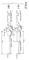
- the conventional bar code reading apparatus scans a margin area which is equal to or greater than a predetermined width W1. It is noted that the last character bar is followed by guard bars, which are followed by the margin area. A low level of the illustrated signal indicates “white", and a black level thereof indicates “black”.
- the conventional bar code reading apparatus cannot read bar codes precisely in a case where as shown in FIG.1B, a bar code is printed in a rectangular white area surrounded by a black area (margin defining area or black frame) so that a margin area before or after the bar code is less than the predetermined width W1 (in the illustrated case, a back margin area after the guard bars has a width W2 less than the predetermined width W1).
- a similar problem may occur in a case where a front portion and/or a back portion itself of a bar code is curved, a bar code label attached on a wrapper is warped due to the presence a good contained therein.
- a more specific object of the present invention is to provide a bar code reading apparatus capable of correctly margin areas located before and after the bar code so that it can be read precisely.
- a bar code reading apparatus comprising scanning means for scanning a bar code including a character bar and a guard bar facing a margin area surrounded by a margin defining area and for generating a pulse signal corresponding to the bar code; and measuring means coupled to the scanning means, for measuring a width of each white bar contained in the bar code and a width of each black bar contained therein and for outputting a measurement signal indicative of the width of the each white or black bar.
- the apparatus comprises first detection means, operatively coupled to the measuring means, for detecting, from the measurement signal, a white bar having a width equal to or greater than a first reference value and for outputting a first detection signal indicative of the width of the white bar; second detection means, operatively coupled to the measuring means, for detecting, from the measurement signal, a white bar having a width equal to or greater than a second reference value and for outputting a second detection signal indicative of the width of the white bar, the second reference being less than the first reference; third detection means, operatively coupled to the measuring means, for detecting, from the measurement signal, a black bar having a width equal or greater than a third reference value and for outputting a third detection signal indicative of the width of the black bar; and logic means coupled to the first, second and third detection means, for receiving the first, second and third detection signals and outputting a margin detection signal indicating detection of the margin area on the basis of the first, second and third detection signals.
- a bar code reading apparatus comprising scanning means for scanning a bar code including a character bar and guard bars facing front and back margin areas surrounded by a margin defining area and for generating a pulse signal corresponding to the bar code; and measuring means coupled to the scanning means, for measuring a width of each white bar contained in the bar code and a width of each black bar contained therein and for outputting a measurement signal indicative of the width of the each white or black bar, the measurement signal includes a time-series of measured value signals T n-1 (n is an integer), T n and T n+1 .
- the apparatus further comprises first holding means coupled to the measuring means, for holding one of the measured value signals until a next one of the measured value signals is output from the measuring means so that when the measured value signal T n+1 is applied to the first holding means, the first holding means outputs the measured signal T n ; second holding means coupled to the first holding means, for holding one of the measured value signals from the first holding means until a next one of the measured value signals is output from the first holding means so that when the measured value signal T n+1 is applied to the second holding means, the second holding means outputs the measured value signal T n-1 ; first multiplying means coupled to the second holding means, for multiplying the measured value signal T n-1 by a first constant A1 and for outputting a signal A1T n-1 ; and first comparing means coupled to the first holding means and the first multiplying means, for determining whether the measured value signal T n is equal to or greater than A1T n-1 and for outputting a first detection signal based on a comparison result.
- the apparatus further comprises second multiplying means coupled to the second holding means, for multiplying the measured value signal T n-1 by a second constant A2 and for outputting a signal A2T n-1 ; second comparing means coupled to the first holding means and the second multiplying means, for determining whether the measured value signal T n is equal to A2T n-1 and for outputting a second detection signal based on a comparison result; third comparing means coupled to the measuring means and the first multiplying means, for determining whether the measured value signal T n+1 is equal to or greater than the signal A1T n-1 and for outputting a third detection signal based on a comparison result; and third multiplying means coupled to the first holding means, for multiplying the measured value signal T n+1 by a third constant A1′ and for outputting a signal A1′T n+1 .
- the apparatus further comprises fourth comparing means coupled to the measuring means and the third multiplying means, for determining whether the measured value signal T n is equal to or greater than A1′T n+1 and for outputting a fourth detection signal based on a comparison result; fourth multiplying means coupled to the measuring means, for multiplying the measured value signal T n+1 by a fifth constant A2′ and for outputting a signal A2′T n+1 ; fifth comparing means coupled to the first holding means and the fourth multiplying means, for determining whether the measured value signal T n is equal to A2′T n+1 and for outputting a fifth detection signal based on a comparison result; sixth comparing means coupled to the second holding means and the third multiplying means, for determining whether the measured value signal T n-1 is equal to or greater than the signal A1′T n+1 and for outputting a sixth detection signal based on a comparison result; and logic means for receiving the first through sixth detection signals and for outputting a margin detection signal indicative of the front and back margins on the basis of
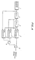
- the interval measuring circuit 1 measures an interval between the leading edges of two consecutive pulses of a binarized signal applied thereto and generates a measurement signal indicative of the measured interval. Further, the interval measuring circuit 1 measures an interval between the trailing edges of two adjacent pulses thereof and generates a measurement signal indicative of the measured interval. That is, the interval measuring circuit 1 measures the sum of the widths of adjacent white and black (black and white) bars. Such an interval is frequently called a delta distance.
- the sum of the widths of the adjacent white and black (black and white) bars which is output from the interval measuring circuit 1 is referred to as a measured interval or width.
- the adder 13 When the adder 13 outputs the measured interval T n+1 , the data holding circuits 3 and 5 output the measured intervals T n and T n-1 , respectively, and the multipliers 21 and 41 output 3.5T n-1 and 1.5T n-1 , respectively.
- the comparator 22 determines whether or not the measured interval T n is equal to or greater than 3.5T n-1 (Tn ⁇ 3.5T n-1 ).
- the comparator 42 determines whether or not the measured interval T n is equal to or greater than 1.5T n-1 (Tn ⁇ 1.5Tn).
- the comparator 61 determines whether or not the measured interval T n+1 is equal to or greater than 3.5T n-1 (T n+1 ⁇ 3.5T n-1 ). Detection signals from the comparators 42 and 61 are supplied to the AND gate 8. Output signals 22 and the AND gate 8 are supplied to the OR gate 10, which outputs a back margin detection signal.
- the comparator 24 compares the measured interval T n with the multiplied interval 3.5T n+1 and determines whether Tn ⁇ 3.5T n+1 .
- the comparator 44 compares the measured interval Tn with the multiplied interval 1.5T n+1 and determines whether Tn ⁇ 1.5T n+1 .
- the comparator 62 compares the measured interval T n-1 with the multiplied interval 3.5 Tn+1 and determines whether T n-1 ⁇ 3.5 T n+1 . Detection signals from the comparators 44 and 62 are input to an AND gate 28.
- An OR gate 30 is supplied with an output signal of the AND gate 28 and a detection signal from the comparator 24.
- An output signal from the OR gate 30 is a front margin detection signal.
Landscapes
- Engineering & Computer Science (AREA)
- Physics & Mathematics (AREA)
- Artificial Intelligence (AREA)
- Computer Vision & Pattern Recognition (AREA)
- General Physics & Mathematics (AREA)
- Theoretical Computer Science (AREA)
- General Health & Medical Sciences (AREA)
- Health & Medical Sciences (AREA)
- Electromagnetism (AREA)
- Toxicology (AREA)
- Quality & Reliability (AREA)
- Signal Processing For Digital Recording And Reproducing (AREA)
- Sorting Of Articles (AREA)
- Character Discrimination (AREA)
- Character Input (AREA)
Applications Claiming Priority (2)
| Application Number | Priority Date | Filing Date | Title |
|---|---|---|---|
| JP1051294A JP2886545B2 (ja) | 1989-03-03 | 1989-03-03 | マージン認識方法及びバーコード読取り装置 |
| JP51294/89 | 1989-03-03 |
Publications (3)
| Publication Number | Publication Date |
|---|---|
| EP0385783A2 true EP0385783A2 (fr) | 1990-09-05 |
| EP0385783A3 EP0385783A3 (en) | 1990-10-24 |
| EP0385783B1 EP0385783B1 (fr) | 1995-05-03 |
Family
ID=12882901
Family Applications (1)
| Application Number | Title | Priority Date | Filing Date |
|---|---|---|---|
| EP90302202A Expired - Lifetime EP0385783B1 (fr) | 1989-03-03 | 1990-03-01 | Lecteur de codes à bâtonnets |
Country Status (4)
| Country | Link |
|---|---|
| US (1) | US5077463A (fr) |
| EP (1) | EP0385783B1 (fr) |
| JP (1) | JP2886545B2 (fr) |
| DE (1) | DE69019048T2 (fr) |
Cited By (7)
| Publication number | Priority date | Publication date | Assignee | Title |
|---|---|---|---|---|
| EP0460509A3 (en) * | 1990-06-02 | 1992-04-08 | Prestek Limited | Binary bar code reader |
| US5486689A (en) * | 1993-01-22 | 1996-01-23 | Intermec Corporation | Method and apparatus for decoding unresolved multi-width bar code symbology profiles |
| WO1996012244A1 (fr) * | 1994-10-17 | 1996-04-25 | Intermec Corporation | Procede et appareil pour decoder des profils non resolus de codes a barres |
| US5514858A (en) * | 1995-02-10 | 1996-05-07 | Intermec Corporation | Method and apparatus for decoding unresolved complex multi-width bar code symbology profiles |
| US5539191A (en) * | 1995-06-22 | 1996-07-23 | Intermec Corporation | Method and apparatus for decoding unresolved bar code profiles using edge finding circuitry |
| US5619027A (en) * | 1995-05-04 | 1997-04-08 | Intermec Corporation | Single width bar code symbology with full character set utilizing robust start/stop characters and error detection scheme |
| US5777309A (en) * | 1995-10-30 | 1998-07-07 | Intermec Corporation | Method and apparatus for locating and decoding machine-readable symbols |
Families Citing this family (9)
| Publication number | Priority date | Publication date | Assignee | Title |
|---|---|---|---|---|
| JP3077616B2 (ja) * | 1997-01-31 | 2000-08-14 | 富士通株式会社 | バーコード読取方法 |
| US5343028A (en) * | 1992-08-10 | 1994-08-30 | United Parcel Service Of America, Inc. | Method and apparatus for detecting and decoding bar code symbols using two-dimensional digital pixel images |
| JPH075564A (ja) * | 1993-06-18 | 1995-01-10 | Fuji Photo Film Co Ltd | フイルムカートリッジ用バーコード読取り装置 |
| US5468946A (en) * | 1994-04-29 | 1995-11-21 | Eastman Kodak Company | Method and apparatus for decoding multi-level bar codes or bi-level bar codes |
| NL9500597A (nl) * | 1995-03-28 | 1996-11-01 | Scantech Bv | Werkwijze en inrichting voor het decoderen van barcodes. |
| JP3083464B2 (ja) * | 1995-08-10 | 2000-09-04 | 富士通株式会社 | バーコード検出装置及び検出方法 |
| US5767498A (en) * | 1996-09-17 | 1998-06-16 | Ncr Corporation | Bar code error scanner |
| JP2001513932A (ja) * | 1997-03-07 | 2001-09-04 | アキュー−ソート・システムズ・インコーポレーテッド | 効果的に位置決めする符号化された象徴記号の走査システム |
| US8682077B1 (en) | 2000-11-28 | 2014-03-25 | Hand Held Products, Inc. | Method for omnidirectional processing of 2D images including recognizable characters |
Family Cites Families (7)
| Publication number | Priority date | Publication date | Assignee | Title |
|---|---|---|---|---|
| US4074852A (en) * | 1976-12-06 | 1978-02-21 | Ncr Corporation | Symbol decoding method and means |
| US4125765A (en) * | 1977-06-27 | 1978-11-14 | International Business Machines Corporation | Label find method and circuit |
| US4130243A (en) * | 1977-07-05 | 1978-12-19 | Stevens Raymond L | Machine readable optical printed symbol format |
| US4379224A (en) * | 1981-05-26 | 1983-04-05 | Honeywell Inc. | Apparatus for interpreting Code 39 bar code data |
| JPS57204977A (en) * | 1981-06-11 | 1982-12-15 | Nippon Denso Co Ltd | Method and device for bar code read |
| JPS63133282A (ja) * | 1986-11-26 | 1988-06-06 | Nippon Denso Co Ltd | バ−コ−ドラベル |
| JPS63244283A (ja) * | 1987-03-31 | 1988-10-11 | Fuji Facom Corp | バ−コ−ド処理装置 |
-
1989
- 1989-03-03 JP JP1051294A patent/JP2886545B2/ja not_active Expired - Fee Related
-
1990
- 1990-03-01 DE DE69019048T patent/DE69019048T2/de not_active Expired - Fee Related
- 1990-03-01 EP EP90302202A patent/EP0385783B1/fr not_active Expired - Lifetime
- 1990-03-02 US US07/487,326 patent/US5077463A/en not_active Expired - Lifetime
Cited By (7)
| Publication number | Priority date | Publication date | Assignee | Title |
|---|---|---|---|---|
| EP0460509A3 (en) * | 1990-06-02 | 1992-04-08 | Prestek Limited | Binary bar code reader |
| US5486689A (en) * | 1993-01-22 | 1996-01-23 | Intermec Corporation | Method and apparatus for decoding unresolved multi-width bar code symbology profiles |
| WO1996012244A1 (fr) * | 1994-10-17 | 1996-04-25 | Intermec Corporation | Procede et appareil pour decoder des profils non resolus de codes a barres |
| US5514858A (en) * | 1995-02-10 | 1996-05-07 | Intermec Corporation | Method and apparatus for decoding unresolved complex multi-width bar code symbology profiles |
| US5619027A (en) * | 1995-05-04 | 1997-04-08 | Intermec Corporation | Single width bar code symbology with full character set utilizing robust start/stop characters and error detection scheme |
| US5539191A (en) * | 1995-06-22 | 1996-07-23 | Intermec Corporation | Method and apparatus for decoding unresolved bar code profiles using edge finding circuitry |
| US5777309A (en) * | 1995-10-30 | 1998-07-07 | Intermec Corporation | Method and apparatus for locating and decoding machine-readable symbols |
Also Published As
| Publication number | Publication date |
|---|---|
| EP0385783B1 (fr) | 1995-05-03 |
| JPH02230482A (ja) | 1990-09-12 |
| DE69019048D1 (de) | 1995-06-08 |
| JP2886545B2 (ja) | 1999-04-26 |
| EP0385783A3 (en) | 1990-10-24 |
| DE69019048T2 (de) | 1995-08-31 |
| US5077463A (en) | 1991-12-31 |
Similar Documents
| Publication | Publication Date | Title |
|---|---|---|
| US5077463A (en) | Bar code reading apparatus | |
| EP0067414B1 (fr) | Procédé et appareil de lecture d'un code à barres | |
| US5128527A (en) | Apparatus for reading a bar code | |
| EP0419226A2 (fr) | Unité pour le traitement de signaux dans un lecteur de caractères à bâtonnets | |
| US3932840A (en) | Error detection and sequence maintaining system for bar-code readers | |
| US6189794B1 (en) | Bar code reader determining unit for determining the true changing point and correcting unit for correcting the false changing point to correct changing point | |
| US4528443A (en) | Bar code reading system and method | |
| EP0462772A2 (fr) | Dispositif de lecture de codes à barres | |
| JP2500859B2 (ja) | バ−コ−ド読取装置 | |
| GB2308710A (en) | Decoding bar codes | |
| JPH096885A (ja) | バーコード復号方式 | |
| US5637853A (en) | Reading indicia by analysis of different light reflecting portions based on signal-to-noise ratios | |
| US7077322B2 (en) | Bar-code reader | |
| US4061900A (en) | Indicia validation system | |
| US5864129A (en) | Bar code digitizer including a voltage comparator | |
| EP1205874B1 (fr) | Méthodes et appareil de traitement de signaux de code-barre à pondération spatiale | |
| JP2915727B2 (ja) | イメージセンサ等のシェージング補正装置 | |
| EP0268983B1 (fr) | Circuit de codage binaire | |
| JP2576370B2 (ja) | Idマーク読み取り装置 | |
| US5331173A (en) | System and method for indicating the location of a benchmark | |
| JPS59201174A (ja) | バ−コ−ド読取装置における信号処理方法 | |
| JPS5936051A (ja) | 紙葉類の穴検知装置 | |
| JP4555952B2 (ja) | バーコード記号読取装置及びそれによるスタートマージン候補検出方法並びにバーコード記号読取方法 | |
| JP2757654B2 (ja) | バーコード復調装置およびバーコード復調方法 | |
| JPS6363949B2 (fr) |
Legal Events
| Date | Code | Title | Description |
|---|---|---|---|
| PUAI | Public reference made under article 153(3) epc to a published international application that has entered the european phase |
Free format text: ORIGINAL CODE: 0009012 |
|
| PUAL | Search report despatched |
Free format text: ORIGINAL CODE: 0009013 |
|
| AK | Designated contracting states |
Kind code of ref document: A2 Designated state(s): DE GB |
|
| RHK1 | Main classification (correction) |
Ipc: G06K 7/016 |
|
| AK | Designated contracting states |
Kind code of ref document: A3 Designated state(s): DE GB |
|
| 17P | Request for examination filed |
Effective date: 19901217 |
|
| 17Q | First examination report despatched |
Effective date: 19930728 |
|
| GRAA | (expected) grant |
Free format text: ORIGINAL CODE: 0009210 |
|
| AK | Designated contracting states |
Kind code of ref document: B1 Designated state(s): DE GB |
|
| REF | Corresponds to: |
Ref document number: 69019048 Country of ref document: DE Date of ref document: 19950608 |
|
| PLBE | No opposition filed within time limit |
Free format text: ORIGINAL CODE: 0009261 |
|
| STAA | Information on the status of an ep patent application or granted ep patent |
Free format text: STATUS: NO OPPOSITION FILED WITHIN TIME LIMIT |
|
| 26N | No opposition filed | ||
| REG | Reference to a national code |
Ref country code: GB Ref legal event code: IF02 |
|
| PGFP | Annual fee paid to national office [announced via postgrant information from national office to epo] |
Ref country code: DE Payment date: 20060223 Year of fee payment: 17 |
|
| PGFP | Annual fee paid to national office [announced via postgrant information from national office to epo] |
Ref country code: GB Payment date: 20060301 Year of fee payment: 17 |
|
| GBPC | Gb: european patent ceased through non-payment of renewal fee |
Effective date: 20070301 |
|
| PG25 | Lapsed in a contracting state [announced via postgrant information from national office to epo] |
Ref country code: DE Free format text: LAPSE BECAUSE OF NON-PAYMENT OF DUE FEES Effective date: 20071002 |
|
| PG25 | Lapsed in a contracting state [announced via postgrant information from national office to epo] |
Ref country code: GB Free format text: LAPSE BECAUSE OF NON-PAYMENT OF DUE FEES Effective date: 20070301 |