EP0385865A2 - Unité de développement et appareil de formation d'images muni de cette unité de développement - Google Patents
Unité de développement et appareil de formation d'images muni de cette unité de développement Download PDFInfo
- Publication number
- EP0385865A2 EP0385865A2 EP90400564A EP90400564A EP0385865A2 EP 0385865 A2 EP0385865 A2 EP 0385865A2 EP 90400564 A EP90400564 A EP 90400564A EP 90400564 A EP90400564 A EP 90400564A EP 0385865 A2 EP0385865 A2 EP 0385865A2
- Authority
- EP
- European Patent Office
- Prior art keywords
- developer
- developing unit
- doctor blade
- developing roller
- carrier
- Prior art date
- Legal status (The legal status is an assumption and is not a legal conclusion. Google has not performed a legal analysis and makes no representation as to the accuracy of the status listed.)
- Ceased
Links
Images



Classifications
-
- G—PHYSICS
- G03—PHOTOGRAPHY; CINEMATOGRAPHY; ANALOGOUS TECHNIQUES USING WAVES OTHER THAN OPTICAL WAVES; ELECTROGRAPHY; HOLOGRAPHY
- G03G—ELECTROGRAPHY; ELECTROPHOTOGRAPHY; MAGNETOGRAPHY
- G03G15/00—Apparatus for electrographic processes using a charge pattern
- G03G15/06—Apparatus for electrographic processes using a charge pattern for developing
- G03G15/08—Apparatus for electrographic processes using a charge pattern for developing using a solid developer, e.g. powder developer
- G03G15/09—Apparatus for electrographic processes using a charge pattern for developing using a solid developer, e.g. powder developer using magnetic brush
Definitions
- the present invention generally relates to developing units and image forming apparatuses having the developing units, and more particularly to a developing unit of an image forming apparatus which develops an electrostatic image which is formed on a peripheral surface of a photosensitive body by use of a 2-component developer which includes toner and carrier and the image forming apparatus which has the developing unit.
- a developing unit In image forming apparatuses such as a printer and a copying machine which form an image by electrophotography, a developing unit usually develops an electrostatic image which is formed on a peripheral surface of a photosensitive body by use of a developer.
- a developing unit generally uses as the developer a 2-component developer which includes toner and magnetic carrier, and it is important from the point of view of maintaining a high picture quality of the prints to maintain a mixture ratio of the toner and the carrier (that is, a toner density) constant.
- the printer employs the so-called face-down system which ejects printed sheets with the face down and stacks the printed sheets so that the pages of the printed sheets become sequential.
- transport paths of the recording sheets should be simplified in order to maintain high stability and high reliability of the printer.
- FIG.1 shows an essential part of a typical conventional printer.
- the printer shown in FIG.1 is designed so that a recording sheet 82 is transported above a photosensitive drum 81 in an approximately horizontal position.
- a developing unit 83 is arranged under a transport path of the recording sheet 82.
- a developing roller 84 which supplies a developer from the developing unit 83 to the photosensitive drum 81 is arranged in an upper half portion of the developing unit 83.
- a cleaning unit 85 is arranged on a downstream side of the photosensitive drum 81 along a transport direction of the recording sheet 82.
- Some printers have a developing unit with means for electronically controlling the toner density to approximately 5 weight percent, for example.
- the carrier is thrown away every time the developer cartridge is changed. For this reason, if possible, it is desirable to minimize the mixture ratio of the carrier. Then, this makes it possible to eliminate the need for controlling the toner density.
- FIG.2 shows an essential part of a conventional printer which has no means for controlling the toner density.
- a developer hopper 91 has an agitator 92 which agitates the developer within the developer hopper 91.
- a developing roller 93 supplies the toner within the developer to a photosensitive drum 100 so as to develop an electrostatic image which is formed on a peripheral surface of the photosensitive drum 100.
- the developing roller 93 is made up of a magnet roll which constitutes a core magnetic portion and a non-magnetic outer sleeve. The outer sleeve and the inner magnet roll can rotate independently.
- a doctor plate 94 which is made of a non-magnetic material is fixed on the developer hopper 91 so as to restrict a thickness of a developer layer which is formed on the developing roller 93.
- the developer is supplied to the photosensitive drum 100 by the developing roller 93.
- the developer is accumulated on the back of the restricting plate 94 and forms a developer accumulation 95.
- the mixture ratio of the carrier at the periphery of the developing roller 93 is not controlled.
- the developing unit shown in FIG.2 operates on the assumption that the carrier of the developer is accumulated on the back of the restricting plate 94 when the developer accumulation 95 is formed.
- the quantity (or level) of the developer within the developer hopper 91 decreases, there are problems in that the toner density decreases in the vicinity of the developing roller 93 and the picture quality of the prints becomes poor.
- Another and more specific object of the present invention is to provide a developing unit for supplying a developer to an image bearing member for visualizing an electrostatic image on the image bearing member into a toner image, comprising a developer hopper for accommodating the developer which includes toner and magnetic carrier, a rotatable developing roller for supplying the developer within the developer hopper and comprising an inner magnet roll and a non-magnetic outer sleeve which has a peripheral surface on which the developer is carried, a doctor blade which is provided within the developer hopper in a vicinity of the developing roller and having a tip end which forms a predetermined gap between the peripheral surface of the outer sleeve so that a thickness of the developer on the peripheral surface of the outer sleeve is restricted to a predetermined thickness, and carrier accumulating means provided in a vicinity of the doctor blade on an upstream side along a direction in which the developer within the developer hopper generally flows towards the developing roller.
- the carrier accumulating means forms a magnetic field so that a developer accumulation formed in a vicinity of the doctor blade has a carrier concentration higher than that of the developer at other parts within the developer hopper.
- the developing unit of the present invention it is possible to positively form the developer accumulation which has a high concentration of the carrier in the vicinity of the developing roller. For this reason, it is possible to ensure an appropriate toner density on the developing roller and stably supply the developer to the photosensitive body without the need to provide a special toner density control device. As a result, prints of improved picture quality can be made in an image forming apparatus which uses the developing unit.
- Still another object of the present invention is to provide an image forming apparatus comprising an image bearing member, a developer hopper for accommodating a developer which includes toner and magnetic carrier, a rotatable developing roller for supplying the developer within the developer hopper to the image bearing member so as to visualize an electrostatic image on the image bearing member into a toner image, where the developing roller comprises an inner magnet roll and a non-magnetic outer sleeve which has a peripheral surface on which the developer is carried, a doctor blade which is provided within the developer hopper in a vicinity of the developing roller, where the doctor blade has a tip end which forms a predetermined gap between the peripheral surface of the outer sleeve so that a thickness of the developer on the peripheral surface of the outer sleeve is restricted to a predetermined thickness, carrier accumulating means provided in a vicinity of the doctor blade on an upstream side along a direction in which the developer within the developer hopper generally flows towards the developing roller, where the carrier accumulating means forms a magnetic field so that a developer accumulation
- the image forming apparatus of the present invention it is possible to positively form the developer accumulation which has a high concentration of the carrier in the vicinity of the developing roller. For this reason, it is possible to ensure an appropriate toner density on the developing roller and stably supply the developer to the photosensitive body without the need to provide a special toner density control device. As a result, prints of improved picture quality can be made.
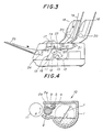
- FIG.3 generally shows a laser printer to which a first embodiment of a developing unit according to the present invention is applied.
- the laser printer shown in FIG.3 comprises a developing unit 10, a photosensitive drum 11, a precharger 12, an electrostatic image forming means 13 which is made up of a light emitting diode (LED) array, for example, a transfer unit 14 a discharger 15, a cleaning unit 16, and a fixing unit 17 which is provided to the left of the transfer unit 14.
- LED light emitting diode
- a recording sheet 19 which is placed on a hopper 18 is fed towards a feed roller 21 by a pick roller 20 which rotates while pressing the recording sheet 19 against the hopper 18.
- the photosensitive drum 11 rotates in a direction R.
- the recording sheet 19 is fed from the hopper 18 by the feed roller 21 through a transport path 22, and a guide roller 23 transports this recording sheet 19 to the transfer unit 14 in synchronism with the rotation of the photosensitive drum 11.
- the formation of a toner image on the photosensitive drum 11 and the transfer of the toner image onto the recording sheet 19 are carried out in the following manner.
- the peripheral surface of the photosensitive drum 11 is uniformly charged by the precharger 12, and an electrostatic image is formed on the peripheral surface of the photosensitive drum 11 depending on an image data which describes an image which is to be printed on the recording sheet 19.
- the electrostatic image on the photosensitive drum 11 is visualized into a toner image by the developing unit 10.
- the toner image is transferred onto the recording sheet 19 by the transfer unit 14, and the recording sheet 19 which has the toner image is transported to the left in FIG.3 where the fixing unit 17 fixes the toner image on the recording sheet 19.
- the recording sheet 19 is ejected face down (that is, with the image facing down) onto a stacker 25 by an eject roller 24.
- the peripheral surface of the photosensitive drum 11 is discharged by the discharger 15 and the residual toner on the photosensitive drum 11 is removed from the peripheral surface by the cleaning unit 16.
- FIG.4 shows the developing unit 10 on an enlarged scale together with the photosensitive drum 11.
- the developing unit 10 comprises a developer hopper 1 which accommodates a developer which includes toner and carrier.
- the toner and carrier are both magnetic materials, and the mixture ratio of the carrier is in a range of approximately 10 to 20 weight percent with respect to the toner.
- the toner is a fine powder mixture of resin, carbon black and magnetite.
- the carrier is a fine powder of ferrite or magnetite.
- it is not essential that the toner is magnetic.
- An agitator 7 is provided within the developer hopper 1 for agitating the developer within the developer hopper 1.
- the agitator 7 rotates clockwise and lifts the developer towards the top left of the developer hopper 1 in FIG.4.
- a developing roller 2 is rotatably provided in an upper half portion of the developer hopper 1.
- the developing roller 2 is made up of an inner magnet roll 2a, and an outer non-magnetic sleeve 2b which has a hollow cylindrical shape and is loosely fitted over the inner magnet roll 2a.
- the inner magnet roll 2a and the outer sleeve 2b are both rotatable, and the inner magnet roll 2a and the outer sleeve 2b may rotate in the same direction S.
- the outer sleeve 2b may rotate in the direction S and the inner magnet roll 2a may rotate in a direction opposite to the direction S.
- the inner magnet roll 2a rotates in the direction S at a first rotational speed and the outer sleeve 2b also rotates in the direction S at a second rotational speed which is smaller than the first rotational speed.
- the magnet roll 2a comprises a plurality of symmetric magnetic poles extending in an axial direction.
- the developer which is lifted by the agitator 7 is supplied to the photosensitive drum 11 by the developing roller 2.
- the electrostatic image formed on the peripheral surface of the photosensitive drum 11 is visualized into a toner image.
- the developing roller 2 which is made up of the inner magnet roll 2a and the outer sleeve 2b which are rotatable is known from the United States Patent No.4,640,880, and the rotation of the inner magnet roll 2a and the outer sleeve 2b in the mutually opposite directions is discussed in Asanae et al., "New Two-Component Electrostatic Developing Method", Hitachi Metals Technical Report, Vol.5, 1989. Accordingly, a detailed description of the developing roller 2 and the rotating direction of the inner magnet roll 2a and the outer sleeve 2b will be omitted in the present specification.
- the inner magnet roll 2a may be fixed to the outer sleeve 2b.
- Such a structure is also well known in the art.
- a doctor blade 3 is fixed on the developer hopper 1 in a vicinity of the developing roller 2.
- the doctor blade 3 is made of a non-magnetic plate which has a width approximately the same as the length of the developing roller 2.
- This doctor blade 3 has a fixed position relative to the developing roller 2 so that a predetermined gap (that is, a doctor gap) is formed between a free tip end of the doctor blade 3 and the peripheral surface of the developing roller 2.
- a predetermined gap that is, a doctor gap
- a carrier accumulating means 4 is provided in a vicinity of the doctor blade 3, that is, on the back side of the doctor blade 3 and on the upstream side along the direction in which the developer flows.
- the carrier accumulating means 4 comprises a magnetic material such as a magnet rod which has a length approximately the same as the length of the inner magnet roll 2a within the developing roller 2.
- the carrier accumulating means 4 By the provision of the carrier accumulating means 4, a magnetic field is formed by the carrier accumulating means 4, and the carrier which has the magnetic characteristic is attracted by this magnetic field. Consequently, a developer accumulation 5 is formed in a vicinity of the carrier accumulating means 4 up to the doctor blade 3 as indicated by hatchings in FIG.4. Of course, the developer accumulation 5 includes the toner and the carrier. However, because the carriers are attracted by the magnetic field formed by the carrier accumulating means 4, the mixture ratio of the carrier in the developer accumulation 5 is high compared to the mixture ratio of the developer in the bottom portion of the developer hopper 1. For example, the mixture ratio of the carrier in the developer accumulation 5 is approximately 50 weight percent.
- the mixture ratio of the carrier is positively maintained to a relatively large value in the developer accumulation 5. For this reason, even when the mixture ratio of the carrier becomes low in the developer which is accommodated within the developer hopper 1, it is possible to stably supply a sufficient quantity of the carrier to the developing roller 2, and an appropriate toner density is always obtainable on the peripheral surface of the developing roller 2. It is also possible to maintain the mixture ratio of the carrier to a large value in an initial state where the quantity (level) of the developer within the developer hopper 1 is large. The picture quality of the prints is thus maintained to a satisfactory quality.
- FIG.5 shows an essential part of a laser printer to which the second embodiment of the developing unit according to the present invention is applied.
- those parts which are basically the same as those corresponding parts in FIGS.3 and 4 are designated by the same reference numerals, and a description thereof will be omitted.
- a doctor blade (restricting plate) 3A and the developing roller 2 are provided on a common bracket 30 so that the position of the doctor blade 3A is fixed relative to the developing roller 2.
- a carrier accumulating means 4A is provided directly on the doctor blade 3A.
- the carrier accumulating means 4A comprises a flexible or rubber magnet.
- TF-RE magnet manufactured by MAGX and FP magnet manufactured by Tokyo Ferrite may be used as the flexible or rubber magnet.
- the photosensitive drum 11 is slightly movable with respect to the developing roller 2 generally in the horizontal direction in FIG.5.
- the developing roller 2 must make a corresponding slight movement.
- a developer accumulation is formed similarly to the first embodiment, and the same effects of the first embodiment are obtainable.
- FIG.6 a description will be given of a toner density versus number of prints characteristic for explaining the effects of the present invention, by referring to FIG.6.
- the ordinate indicates the toner density in weight percent
- the abscissa indicates the number of prints made. As the number of prints increases, the level of the developer within the developer hopper 1 decreases.
- the developing roller 2 has a diameter of 20 mm, and the outer sleeve 2b is made of aluminum.
- the outer sleeve 2b is rotated at 162 rpm in the direction S, and the inner magnet roll 2a is rotated at 1023 rpm in the same direction S.
- the inner magnet roll 2a has 8 symmetric magnetic poles with 750 ⁇ 50 G (Gauss) between the poles, and the magnetic field variance along the longitudinal direction of the developing roller 2 is 80 G or less.
- the doctor blade 3A is made of stainless steel which is non-magnetic.
- the carrier accumulating means 4A is made up of a flexible or rubber magnet having a size of 3mm x 8 mm x 200 mm and having a maximum energy product of 106 G Oe (Gaus-Oersted).
- the flexible or rubber magnet may be isotropic or anisotrpic.
- each print which is made has a printed area (black area) which is approximately 5 % of the total area of the recording sheet 19.
- a characteristic I shown in FIG.6 is obtained with the same structure excluding the carrier accumulating means 4A. It can be readily seen by comparing the characteristics I and II that the provision of the carrier accumulating means 4A considerably stabilizes the toner density as the developer level within the developer hopper 1 decreases.
- FIG.7 a description will be given of a third embodiment of the developing unit according to the present invention, by referring to FIG.7.
- those parts which are the same as those corresponding parts in FIG.5 are designated by the same reference numerals, and a description thereof will be omitted.
- a doctor blade 3B itself is magnetic and constitutes a carrier accumulating means 4B.
- the doctor blade 3B is made of a metal, a zinc plated steel, an electrolytic zinc-coated steel sheet (SECC), a magnet and the like. According to this embodiment, substantially the same effects are obtainable as in the first and second embodiments.
- the doctor blade and the developing roller are provided in the upper half portion of the developer hopper.
- the present invention is not limited to such an arrangement.
- the doctor blade and the developing roller may be provided in the lower half portion of the developer hopper.
- the printer may be used in any position.
- the present invention is not limited to the application to the printer.
- the present invention is applicable to other image forming apparatuses such as copying machines and facsimile machines.
- the developing unit may take a form of a cartridge which is replaceable.
- the image forming apparatus is not necessarily limited to the electrophotographic apparatus and may be an electrostatic apparatuses.
- cross sectional shape of the carrier accumulating means 4A is not limited to square or rectangular shapes, and may have other shapes such as circular and oval shapes.
Landscapes
- Physics & Mathematics (AREA)
- General Physics & Mathematics (AREA)
- Dry Development In Electrophotography (AREA)
- Magnetic Brush Developing In Electrophotography (AREA)
Applications Claiming Priority (2)
| Application Number | Priority Date | Filing Date | Title |
|---|---|---|---|
| JP46902/89 | 1989-02-28 | ||
| JP1046902A JPH02226279A (ja) | 1989-02-28 | 1989-02-28 | 印刷装置の現像器 |
Publications (2)
| Publication Number | Publication Date |
|---|---|
| EP0385865A2 true EP0385865A2 (fr) | 1990-09-05 |
| EP0385865A3 EP0385865A3 (fr) | 1991-07-31 |
Family
ID=12760293
Family Applications (1)
| Application Number | Title | Priority Date | Filing Date |
|---|---|---|---|
| EP19900400564 Ceased EP0385865A3 (fr) | 1989-02-28 | 1990-02-28 | Unité de développement et appareil de formation d'images muni de cette unité de développement |
Country Status (2)
| Country | Link |
|---|---|
| EP (1) | EP0385865A3 (fr) |
| JP (1) | JPH02226279A (fr) |
Cited By (3)
| Publication number | Priority date | Publication date | Assignee | Title |
|---|---|---|---|---|
| EP0668546A3 (fr) * | 1994-02-16 | 1996-04-03 | Brother Ind Ltd | Unité de développement pour utilisation dans un appareil de formation d'images. |
| EP0666517A3 (fr) * | 1994-02-08 | 1996-04-03 | Brother Ind Ltd | Unité de développement utilisant de toner. |
| US5630198A (en) * | 1995-12-28 | 1997-05-13 | Brother Kogyo Kabushiki Kaisha | Toner fillable cartridge having protrusions engageable with a development case shutter |
Families Citing this family (2)
| Publication number | Priority date | Publication date | Assignee | Title |
|---|---|---|---|---|
| JP2901197B2 (ja) * | 1990-10-24 | 1999-06-07 | 日立金属株式会社 | 現像装置 |
| US6055401A (en) * | 1995-09-12 | 2000-04-25 | Fujitsu Limited | Electrophotographic image-forming apparatus having developing device which includes a plurality of developing rollers |
Family Cites Families (7)
| Publication number | Priority date | Publication date | Assignee | Title |
|---|---|---|---|---|
| JPS58143360A (ja) * | 1982-02-19 | 1983-08-25 | Canon Inc | 現像方法 |
| JPS59182464A (ja) * | 1983-04-01 | 1984-10-17 | Hitachi Ltd | 電子写真法 |
| US4676192A (en) * | 1983-09-30 | 1987-06-30 | Minolta Camera Kabushiki Kaisha | Dry process developing apparatus |
| JPS61273564A (ja) * | 1985-05-30 | 1986-12-03 | Nec Corp | キヤリアプロテクタ− |
| DE3650246T2 (de) * | 1985-09-17 | 1995-07-20 | Canon Kk | Entwicklungsverfahren und Gerät. |
| JPS62135862A (ja) * | 1985-12-10 | 1987-06-18 | Canon Inc | 現像装置 |
| JPS63177757A (ja) * | 1987-01-19 | 1988-07-21 | Morinaga & Co Ltd | 多重球状中空焼菓子の製造法 |
-
1989
- 1989-02-28 JP JP1046902A patent/JPH02226279A/ja active Pending
-
1990
- 1990-02-28 EP EP19900400564 patent/EP0385865A3/fr not_active Ceased
Cited By (5)
| Publication number | Priority date | Publication date | Assignee | Title |
|---|---|---|---|---|
| EP0666517A3 (fr) * | 1994-02-08 | 1996-04-03 | Brother Ind Ltd | Unité de développement utilisant de toner. |
| US5576814A (en) * | 1994-02-08 | 1996-11-19 | Brother Kogyo Kabushiki Kaisha | Developing unit using toner having a magnetic shield between the agitation chamber and a developing roller |
| EP0668546A3 (fr) * | 1994-02-16 | 1996-04-03 | Brother Ind Ltd | Unité de développement pour utilisation dans un appareil de formation d'images. |
| US5608501A (en) * | 1994-02-16 | 1997-03-04 | Brother Kogyo Kabushiki Kaisha | Development unit and toner cartridge for use in an image formation apparatus |
| US5630198A (en) * | 1995-12-28 | 1997-05-13 | Brother Kogyo Kabushiki Kaisha | Toner fillable cartridge having protrusions engageable with a development case shutter |
Also Published As
| Publication number | Publication date |
|---|---|
| EP0385865A3 (fr) | 1991-07-31 |
| JPH02226279A (ja) | 1990-09-07 |
Similar Documents
| Publication | Publication Date | Title |
|---|---|---|
| US6834175B2 (en) | Developer agitating member | |
| US6421516B1 (en) | Developing device and image forming apparatus having a restricted developer surface level feature | |
| US6912365B2 (en) | Process cartridge, unit, and electrophotographic image forming apparatus | |
| US20080267672A1 (en) | Developing device, image supporter unit, and image formation apparatus | |
| US5848343A (en) | Electrophotographic image-forming apparatus with uniform toner usage control | |
| JPH07107618B2 (ja) | 現像装置 | |
| US5943538A (en) | Toner supplying device for developing unit | |
| JP3382541B2 (ja) | 現像装置 | |
| US6813462B2 (en) | Electro-photographic developing unit | |
| EP1795974B1 (fr) | Dispositif de développement, cartouche de traitement et appareil de formation d'images | |
| EP0385865A2 (fr) | Unité de développement et appareil de formation d'images muni de cette unité de développement | |
| EP0666517B1 (fr) | Unité de développement utilisant de toner | |
| JPH06110333A (ja) | 磁気ブラシ現像器 | |
| JP4528055B2 (ja) | 現像装置及びそれを用いた画像形成装置 | |
| US5576813A (en) | Developing device having a dispersion blocking plate and electrostatic recording device including the same | |
| JP4147120B2 (ja) | 2成分現像装置、プロセスカートリッジ、画像形成装置 | |
| EP0311020A2 (fr) | Positionnement angulaire des aimants dans un rouleau de développement utilisé dans des appareils électrophotographiques ou analogues | |
| US11537065B2 (en) | Developing unit, process cartridge, and image forming apparatus using toner to develop toner image | |
| JP2005148366A (ja) | 画像形成装置 | |
| JPH0222951B2 (fr) | ||
| JP3860907B2 (ja) | 現像装置 | |
| GB2226156A (en) | Developing device for image forming apparatus | |
| JP3936836B2 (ja) | 現像装置及び画像形成装置 | |
| JP2870668B2 (ja) | 攪拌装置 | |
| US20070264041A1 (en) | Local suppression of unwanted toner emissions |
Legal Events
| Date | Code | Title | Description |
|---|---|---|---|
| PUAI | Public reference made under article 153(3) epc to a published international application that has entered the european phase |
Free format text: ORIGINAL CODE: 0009012 |
|
| AK | Designated contracting states |
Kind code of ref document: A2 Designated state(s): DE FR GB |
|
| PUAL | Search report despatched |
Free format text: ORIGINAL CODE: 0009013 |
|
| AK | Designated contracting states |
Kind code of ref document: A3 Designated state(s): DE FR GB |
|
| 17P | Request for examination filed |
Effective date: 19911210 |
|
| 17Q | First examination report despatched |
Effective date: 19930304 |
|
| STAA | Information on the status of an ep patent application or granted ep patent |
Free format text: STATUS: THE APPLICATION HAS BEEN REFUSED |
|
| 18R | Application refused |
Effective date: 19940328 |