EP0385902A1 - Vorrichtung zum Füllen von Petri-Schalen - Google Patents
Vorrichtung zum Füllen von Petri-Schalen Download PDFInfo
- Publication number
- EP0385902A1 EP0385902A1 EP90460010A EP90460010A EP0385902A1 EP 0385902 A1 EP0385902 A1 EP 0385902A1 EP 90460010 A EP90460010 A EP 90460010A EP 90460010 A EP90460010 A EP 90460010A EP 0385902 A1 EP0385902 A1 EP 0385902A1
- Authority
- EP
- European Patent Office
- Prior art keywords
- plate
- boxes
- box
- sole
- station
- Prior art date
- Legal status (The legal status is an assumption and is not a legal conclusion. Google has not performed a legal analysis and makes no representation as to the accuracy of the status listed.)
- Granted
Links
- 238000012546 transfer Methods 0.000 claims abstract description 27
- 230000008878 coupling Effects 0.000 claims abstract description 5
- 238000010168 coupling process Methods 0.000 claims abstract description 5
- 238000005859 coupling reaction Methods 0.000 claims abstract description 5
- 229920001817 Agar Polymers 0.000 claims description 26
- 239000008272 agar Substances 0.000 claims description 26
- 238000001816 cooling Methods 0.000 claims description 11
- 238000003860 storage Methods 0.000 claims description 8
- 230000005679 Peltier effect Effects 0.000 claims description 5
- 230000005855 radiation Effects 0.000 claims description 5
- 230000002070 germicidal effect Effects 0.000 claims description 4
- 238000002347 injection Methods 0.000 claims description 3
- 239000007924 injection Substances 0.000 claims description 3
- 230000005693 optoelectronics Effects 0.000 claims description 3
- 238000001514 detection method Methods 0.000 claims description 2
- 238000004140 cleaning Methods 0.000 description 7
- 239000000203 mixture Substances 0.000 description 4
- 229920003023 plastic Polymers 0.000 description 4
- 230000000717 retained effect Effects 0.000 description 4
- 238000006073 displacement reaction Methods 0.000 description 3
- 239000012153 distilled water Substances 0.000 description 3
- 239000007788 liquid Substances 0.000 description 3
- 238000004519 manufacturing process Methods 0.000 description 3
- BASFCYQUMIYNBI-UHFFFAOYSA-N platinum Chemical compound [Pt] BASFCYQUMIYNBI-UHFFFAOYSA-N 0.000 description 3
- XLYOFNOQVPJJNP-UHFFFAOYSA-N water Chemical compound O XLYOFNOQVPJJNP-UHFFFAOYSA-N 0.000 description 3
- 229910000838 Al alloy Inorganic materials 0.000 description 2
- 239000003570 air Substances 0.000 description 2
- 238000009826 distribution Methods 0.000 description 2
- 229940090044 injection Drugs 0.000 description 2
- 239000000696 magnetic material Substances 0.000 description 2
- 244000005700 microbiome Species 0.000 description 2
- 235000008935 nutritious Nutrition 0.000 description 2
- 230000002093 peripheral effect Effects 0.000 description 2
- 239000007787 solid Substances 0.000 description 2
- 125000006850 spacer group Chemical class 0.000 description 2
- 108010010803 Gelatin Proteins 0.000 description 1
- 230000004913 activation Effects 0.000 description 1
- 238000013019 agitation Methods 0.000 description 1
- 239000012080 ambient air Substances 0.000 description 1
- 244000052616 bacterial pathogen Species 0.000 description 1
- 230000015556 catabolic process Effects 0.000 description 1
- 230000007547 defect Effects 0.000 description 1
- 238000013461 design Methods 0.000 description 1
- 238000011161 development Methods 0.000 description 1
- 230000000694 effects Effects 0.000 description 1
- 230000005670 electromagnetic radiation Effects 0.000 description 1
- 238000000605 extraction Methods 0.000 description 1
- 238000005429 filling process Methods 0.000 description 1
- 239000008273 gelatin Substances 0.000 description 1
- 229920000159 gelatin Polymers 0.000 description 1
- 235000019322 gelatine Nutrition 0.000 description 1
- 235000011852 gelatine desserts Nutrition 0.000 description 1
- 230000014759 maintenance of location Effects 0.000 description 1
- 238000000034 method Methods 0.000 description 1
- 230000000813 microbial effect Effects 0.000 description 1
- 238000011017 operating method Methods 0.000 description 1
- 230000002572 peristaltic effect Effects 0.000 description 1
- 230000000750 progressive effect Effects 0.000 description 1
- 230000001681 protective effect Effects 0.000 description 1
- 238000011160 research Methods 0.000 description 1
- 238000005096 rolling process Methods 0.000 description 1
- 238000005070 sampling Methods 0.000 description 1
- 239000004065 semiconductor Substances 0.000 description 1
- 239000010935 stainless steel Substances 0.000 description 1
- 229910001220 stainless steel Inorganic materials 0.000 description 1
- 238000013519 translation Methods 0.000 description 1
- 238000009423 ventilation Methods 0.000 description 1
Images



Classifications
-
- B—PERFORMING OPERATIONS; TRANSPORTING
- B65—CONVEYING; PACKING; STORING; HANDLING THIN OR FILAMENTARY MATERIAL
- B65B—MACHINES, APPARATUS OR DEVICES FOR, OR METHODS OF, PACKAGING ARTICLES OR MATERIALS; UNPACKING
- B65B43/00—Forming, feeding, opening or setting-up containers or receptacles in association with packaging
- B65B43/42—Feeding or positioning bags, boxes, or cartons in the distended, opened, or set-up state; Feeding preformed rigid containers, e.g. tins, capsules, glass tubes, glasses, to the packaging position; Locating containers or receptacles at the filling position; Supporting containers or receptacles during the filling operation
- B65B43/44—Feeding or positioning bags, boxes, or cartons in the distended, opened, or set-up state; Feeding preformed rigid containers, e.g. tins, capsules, glass tubes, glasses, to the packaging position; Locating containers or receptacles at the filling position; Supporting containers or receptacles during the filling operation from supply magazines
-
- C—CHEMISTRY; METALLURGY
- C12—BIOCHEMISTRY; BEER; SPIRITS; WINE; VINEGAR; MICROBIOLOGY; ENZYMOLOGY; MUTATION OR GENETIC ENGINEERING
- C12M—APPARATUS FOR ENZYMOLOGY OR MICROBIOLOGY; APPARATUS FOR CULTURING MICROORGANISMS FOR PRODUCING BIOMASS, FOR GROWING CELLS OR FOR OBTAINING FERMENTATION OR METABOLIC PRODUCTS, i.e. BIOREACTORS OR FERMENTERS
- C12M23/00—Constructional details, e.g. recesses, hinges
- C12M23/02—Form or structure of the vessel
- C12M23/10—Petri dish
-
- C—CHEMISTRY; METALLURGY
- C12—BIOCHEMISTRY; BEER; SPIRITS; WINE; VINEGAR; MICROBIOLOGY; ENZYMOLOGY; MUTATION OR GENETIC ENGINEERING
- C12M—APPARATUS FOR ENZYMOLOGY OR MICROBIOLOGY; APPARATUS FOR CULTURING MICROORGANISMS FOR PRODUCING BIOMASS, FOR GROWING CELLS OR FOR OBTAINING FERMENTATION OR METABOLIC PRODUCTS, i.e. BIOREACTORS OR FERMENTERS
- C12M23/00—Constructional details, e.g. recesses, hinges
- C12M23/48—Holding appliances; Racks; Supports
-
- C—CHEMISTRY; METALLURGY
- C12—BIOCHEMISTRY; BEER; SPIRITS; WINE; VINEGAR; MICROBIOLOGY; ENZYMOLOGY; MUTATION OR GENETIC ENGINEERING
- C12M—APPARATUS FOR ENZYMOLOGY OR MICROBIOLOGY; APPARATUS FOR CULTURING MICROORGANISMS FOR PRODUCING BIOMASS, FOR GROWING CELLS OR FOR OBTAINING FERMENTATION OR METABOLIC PRODUCTS, i.e. BIOREACTORS OR FERMENTERS
- C12M23/00—Constructional details, e.g. recesses, hinges
- C12M23/50—Means for positioning or orientating the apparatus
-
- C—CHEMISTRY; METALLURGY
- C12—BIOCHEMISTRY; BEER; SPIRITS; WINE; VINEGAR; MICROBIOLOGY; ENZYMOLOGY; MUTATION OR GENETIC ENGINEERING
- C12M—APPARATUS FOR ENZYMOLOGY OR MICROBIOLOGY; APPARATUS FOR CULTURING MICROORGANISMS FOR PRODUCING BIOMASS, FOR GROWING CELLS OR FOR OBTAINING FERMENTATION OR METABOLIC PRODUCTS, i.e. BIOREACTORS OR FERMENTERS
- C12M29/00—Means for introduction, extraction or recirculation of materials, e.g. pumps
-
- C—CHEMISTRY; METALLURGY
- C12—BIOCHEMISTRY; BEER; SPIRITS; WINE; VINEGAR; MICROBIOLOGY; ENZYMOLOGY; MUTATION OR GENETIC ENGINEERING
- C12M—APPARATUS FOR ENZYMOLOGY OR MICROBIOLOGY; APPARATUS FOR CULTURING MICROORGANISMS FOR PRODUCING BIOMASS, FOR GROWING CELLS OR FOR OBTAINING FERMENTATION OR METABOLIC PRODUCTS, i.e. BIOREACTORS OR FERMENTERS
- C12M41/00—Means for regulation, monitoring, measurement or control, e.g. flow regulation
- C12M41/48—Automatic or computerized control
-
- C—CHEMISTRY; METALLURGY
- C12—BIOCHEMISTRY; BEER; SPIRITS; WINE; VINEGAR; MICROBIOLOGY; ENZYMOLOGY; MUTATION OR GENETIC ENGINEERING
- C12M—APPARATUS FOR ENZYMOLOGY OR MICROBIOLOGY; APPARATUS FOR CULTURING MICROORGANISMS FOR PRODUCING BIOMASS, FOR GROWING CELLS OR FOR OBTAINING FERMENTATION OR METABOLIC PRODUCTS, i.e. BIOREACTORS OR FERMENTERS
- C12M99/00—Subject matter not otherwise provided for in other groups of this subclass
-
- G—PHYSICS
- G01—MEASURING; TESTING
- G01N—INVESTIGATING OR ANALYSING MATERIALS BY DETERMINING THEIR CHEMICAL OR PHYSICAL PROPERTIES
- G01N35/00—Automatic analysis not limited to methods or materials provided for in any single one of groups G01N1/00 - G01N33/00; Handling materials therefor
- G01N35/02—Automatic analysis not limited to methods or materials provided for in any single one of groups G01N1/00 - G01N33/00; Handling materials therefor using a plurality of sample containers moved by a conveyor system past one or more treatment or analysis stations
- G01N35/04—Details of the conveyor system
- G01N2035/0401—Sample carriers, cuvettes or reaction vessels
- G01N2035/0403—Sample carriers with closing or sealing means
- G01N2035/0405—Sample carriers with closing or sealing means manipulating closing or opening means, e.g. stoppers, screw caps, lids or covers
-
- G—PHYSICS
- G01—MEASURING; TESTING
- G01N—INVESTIGATING OR ANALYSING MATERIALS BY DETERMINING THEIR CHEMICAL OR PHYSICAL PROPERTIES
- G01N35/00—Automatic analysis not limited to methods or materials provided for in any single one of groups G01N1/00 - G01N33/00; Handling materials therefor
- G01N35/02—Automatic analysis not limited to methods or materials provided for in any single one of groups G01N1/00 - G01N33/00; Handling materials therefor using a plurality of sample containers moved by a conveyor system past one or more treatment or analysis stations
- G01N35/04—Details of the conveyor system
- G01N2035/0401—Sample carriers, cuvettes or reaction vessels
- G01N2035/0406—Individual bottles or tubes
- G01N2035/041—Individual bottles or tubes lifting items out of a rack for access
-
- G—PHYSICS
- G01—MEASURING; TESTING
- G01N—INVESTIGATING OR ANALYSING MATERIALS BY DETERMINING THEIR CHEMICAL OR PHYSICAL PROPERTIES
- G01N35/00—Automatic analysis not limited to methods or materials provided for in any single one of groups G01N1/00 - G01N33/00; Handling materials therefor
- G01N35/02—Automatic analysis not limited to methods or materials provided for in any single one of groups G01N1/00 - G01N33/00; Handling materials therefor using a plurality of sample containers moved by a conveyor system past one or more treatment or analysis stations
- G01N35/04—Details of the conveyor system
- G01N2035/0439—Rotary sample carriers, i.e. carousels
- G01N2035/0444—Rotary sample carriers, i.e. carousels for cuvettes or reaction vessels
-
- G—PHYSICS
- G01—MEASURING; TESTING
- G01N—INVESTIGATING OR ANALYSING MATERIALS BY DETERMINING THEIR CHEMICAL OR PHYSICAL PROPERTIES
- G01N35/00—Automatic analysis not limited to methods or materials provided for in any single one of groups G01N1/00 - G01N33/00; Handling materials therefor
- G01N35/02—Automatic analysis not limited to methods or materials provided for in any single one of groups G01N1/00 - G01N33/00; Handling materials therefor using a plurality of sample containers moved by a conveyor system past one or more treatment or analysis stations
- G01N35/04—Details of the conveyor system
- G01N2035/0474—Details of actuating means for conveyors or pipettes
- G01N2035/0477—Magnetic
Definitions
- the present invention relates to a device for filling petri dishes.
- the Petri dishes are small circular contour boxes, made of transparent plastic, which contain a nutritious product such as a mixture of agar and distilled water; they serve as a development medium for cultures containing microorganisms and are used in large numbers by analytical laboratories, particularly in medical research and in industry.
- the agar / distilled water mixture is presented at ordinary temperature in a solid form, having the consistency of a gelatin.
- the mixture Before being introduced into the boxes at a temperature of the order of 42 to 50 ° C, the mixture is brought to a temperature of the order of 100 ° C to take a liquid form; it is thus distributed in the boxes to form a regular layer, with a flat surface.
- the box can be used only after the product has hardened, the hardening time being of the order of ten minutes at room temperature.
- a filling device in which the boxes to be filled are conveyed one after the other by means of a horizontal turntable, to a filling station which includes a nozzle of agar distribution.
- the boxes are presented at the agar dispensing station in the open state, that is to say cover kept apart above the bottom, one after the other.
- the rotary transfer plate is composed of two horizontal coaxial and superimposed circular plates, which are each pierced with circular openings regularly distributed at their periphery and in correspondence with each other; the openings of the upper plate have a diameter slightly smaller than that of the covers but slightly larger than that of the case backs, so that they allow the passage of the latter by retaining only the covers; on the contrary, the lower plate is provided with openings shaped to receive and support the funds during their transfer.
- the agar dispensing nozzle extends between the two plates, which makes it possible to supply agar to the bottoms of boxes which are presented in turn at the filling station.
- This known device is equipped with a single carousel which acts both as a dispensing station for empty boxes and as a receiving station for full boxes; the carousel contains several stacks of boxes which are distributed around its periphery by forming columns, the latter being retained by vertical rods.
- the box capacity of the device and therefore its autonomy, are limited due to the use of a single carousel; an increase in the number of columns per carousel would pose difficulties linked to the weight and the bulk thereof.
- the system for transferring the boxes from the carousel to the transfer tray, and vice versa from this to the carousel (after filling) is relatively complicated and subject to breakdowns because it requires the use of mobile means which ensure the retention of the penultimate box of the column during the removal or introduction of the last, that is to say of the lowest box; the complexity of this system also requires working at a relatively low rate.
- the stacking of the full cans is done while the product is still liquid, which is a cause of lack of surface flatness of the agar in the cans, this due to the inevitable agitation of the product which appears during storage; outside, a defect in flatness is likely to pose difficulties in particular during the subsequent analyzes made by reading using a camera.
- the invention aims to solve these various problems by proposing a device of the type mentioned which is of simple design and of safe and reliable operation, which works at high speed, which is easy to maintain, in particular with a view to cleaning, which has a high storage capacity, that is to say which can contain and process without external intervention a very large number of dishes, which makes it possible to obtain these agar layers with a very flat surface, and which produces petri dishes immediately usable (without waiting period).
- the device which - like the already known device mentioned above - comprises a rotating transfer plate, capable of successively and step by step opening open boxes (lids kept apart above the bottom) of a dispensing station empty boxes at a filling station, then from the latter to a receiving station for filled boxes, this tray being composed of two horizontal circular coaxial and superimposed plates, each pierced with a series of circular openings regularly distributed around their periphery and in correspondence with each other, the openings of the upper plate having a diameter slightly smaller than that of the lids but slightly larger than that of the bottoms, so that they allow the passage of the latter by retaining only the lids , is characterized in that: - On the one hand, the openings of the lower plate have a diameter slightly larger than that of the bottoms so that they also allow the passage of the latter; - on the other hand, said transfer plate rests, by its lower plate on a flat and horizontal fixed sole, so that during their transfer by means of said
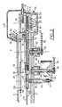
- the device shown schematically in top view in Figure 1 has the general shape of a rectangular box covered by a plate 3 of stainless steel. Inside the box are installed the various control devices of the device, in particular the motors for driving moving parts and the electronic components constituting the microprocessor driving the machine; the latter is connected to a keyboard 1000 which in a known manner allows the operator to respond to requests for instructions from the microprocessor and to give it instructions according to the operation he wishes to perform; these instructions relate in particular to the number of boxes to be treated and the volume of agar to be distributed in each box.
- the front face of the device directed downwards in FIG. 1, has been designated by the reference 102, the face which faces the operator.
- a rotary plate 1 In the central part of the device, near this front face, is mounted a rotary plate 1.
- the filling station for boxes of nutritious product located on the front face of the device in the central part of it, comprises a dispensing nozzle or cannula 70 which is connected by a flexible conduit 74 to a source 76, in this case a container containing the agar in the liquid state.
- a suitable pump 75 preferably of the peristaltic type, is adapted to pump at the source 76, without jerking (so as not to generate bubbles) successive volumes of agar which are then injected into the dishes by the nozzle 70.
- the arrow H symbolizes the passage of the agar in the conduit 74.
- the pump 75 can be one or two-way and adapted to dispense a variable volume, preferably between 3 and 25 ml.
- the filling rate is advantageously around 10 cans per minute for 15 ml of product.
- the device comprises, in each of the dispensing and receiving stations, a rotary disc 20 for driving a carousel containing the boxes.
- This disc is rotatably mounted around a vertical axis Y and is driven by a suitable electric motor housed under the plate 3, inside the box forming the frame of the device.
- the discs 20 have centering and drive pins 21 of the carousels.
- each of the carousels is composed of a horizontal lower disc 22 and an upper crown 27; the disc 22 has orifices 23 suitable for being placed on the disc 20 and cooperating with the centering and drive pins 21.
- This disc comprises a series of peripheral openings 24, angularly distributed in a regular manner; these openings 24 have a diameter slightly greater than that of the boxes.
- FIG. 3 only an opening 24 has been shown; nine openings 24 are provided offset by 40 ° relative to each other.
- the parts 22, 27 are connected to each other by means of a series of vertical rods 25; four rods 25 are provided per pair of openings 24, 26, these rods serving to retain a stack of boxes making up a vertical column housed between these rods.
- Each column advantageously contains fifty Petri dishes, so that the carousel can contain a total of 450 dishes.
- at least one of these rods, located towards the outside of the carousel, is flexible and its upper end is movable, which facilitates the removal of the column from boxes or from 'a part of the boxes constituting this column.
- the carousels after being placed on the discs 20a and 20b, are driven step by step by the latter in a direction which, when viewed from above, is the opposite direction from that of the hands of a watch, this direction being shown by arrows F2a and F2b in Figure 1.
- the transfer plate 1 consists of two circular plates 10, 11 secured to one another by means of a series of spacers 13. They are advantageously made of a high-strength plastic.
- the upper plate 10 is pierced with a series of nine openings arranged at its periphery and regularly distributed every 40 °. Each of these openings 100 has a recess 101 of slightly larger diameter directed upwards.
- the lower plate 11 has a slightly smaller diameter than the plate 10 and also has nine peripheral openings 110, distributed every 40 °, the vertical axes of which coincide with those of the openings 100. Due to the smaller diameter of the plate 11, the openings 110 open to the outside by notches.
- Petri dishes are small transparent plastic dishes made up of two parts, namely a bottom and a lid. Each of these parts has a side wall of different diameter, the wall of the cover covering that of the bottom when the box is closed; this implementation is practically frictionless, so that the removal of the cover is effortless.
- the circular opening 100 of the lower plate has a smaller diameter than that of the cover, so that if a box is moved up and down in the axis of this opening, the cover remains retained by the edge of the recess 101.
- the diameter of the opening 100 is slightly larger than that of the bottom of the box, so that the latter can continue to descend by crossing the opening 100 and being released of the cover; the circular opening 110 also has a diameter slightly larger than that of the bottom of the box.
- a series of magnets 12 for example also nine in number, regularly distributed angularly every 40 °.
- the plate 1 rests by means of a series of balls 14, for example three balls arranged at 120 °, which are advantageously housed in spacers 13, on a fixed horizontal plate 55, which will be called the sole.
- the balls could advantageously be replaced by ball bearings.
- the plate 55 is made of a non-magnetic material, preferably an aluminum alloy.
- the bearing 52 serves to guide in rotation, by means of appropriate ball bearings, a shaft 60 of vertical axis X.
- the latter is integral with a disc 6, also made of non-magnetic material such as an aluminum alloy , which is arranged horizontally just below the sole 55; the disc 6 carries a series of magnets 61 identical to the magnets 12 and each arranged in correspondence with the latter.
- the shaft 60 is rotated by a suitable motor, not shown, for example by means of a toothed belt 63 meshing on a pinion 62 wedged on the shaft 60.
- the plate 1 is placed on the sole 55 of so that the axis of the plate is close to the axis X, by mutual magnetic attraction of the magnets 61 and 12, the plate is positioned exactly in alignment with the disc, so that the magnets 12 and 61 are exactly opposite; thereafter, the rotation of the disc 6 achieves, by magnetic coupling, the corresponding drive of the plate 1.
- the upper plate 3 is pierced with an opening 30a, respectively 30b, the diameter of which is slightly greater than that of the boxes.
- each pair of openings 100, 110 can come into correspondence with these two openings 30a, 30b.
- the pistons 4 have an upper face 48 with a chamfered edge 401 and having an inclined face 400 which, as will be seen below, facilitates the passage of the bottom of the boxes on the face 48.
- the piston head 4 is carried by a rod 40, the lower end of which is provided with a rolling roller 41 which bears against an annular cam track 44; this cam path is fixed on a disc 42, the latter being wedged on a vertical shaft 43 guided in rotation in ball bearings housed in the bore 51.
- a suitable electric geared motor (not shown) drives the cam 42 in rotation, by means of a toothed belt 46 which meshes with a pinion 45 secured to the shaft 43.
- the rotation of the cam 42 causes the vertical displacement of the piston.
- the profile of the cam is determined so as to give the piston three determined durable positions, a low position, a high position and an intermediate position.
- a cooling device 8 On the side of the front face of the device, the frame plate 5 is hollowed out so as to form a box 53 extending under part of the trajectory of the boxes when they are transported by the turntable 1.
- a cooling device 8 In this box 53 is arranged a cooling device 8.
- the latter consists of a Peltier cooling module 8, suitably supplied with electrical energy by means not shown in the figures.
- a Peltier effect cell behaves like a heat pump, with no moving parts. It is composed of a cold face where the thermal energy is absorbed by the electrons passing from one semiconductor to another; the current source provides the energy necessary to pass the electrons through the system; the hot side releases energy to the ambient air through a heat exchanger.
- the cold face 80 of the module 8 is glued directly under the sole 55, while the hot face 81, directed downwards, carries fins 82 for dissipating heat.
- a ventilation system comprising one or more fans 83 makes it possible to pass an air flow at room temperature into the box 53 in order to eliminate the heat laughs dissipated by these fins 82.
- the module 8 therefore performs constant cooling of the sole 55.
- modules 8 can be provided, advantageously connected in series, and arranged in an arc so as to cover at least part of the trajectory of the boxes, when the latter circulate in the device by means of the turntable 1.
- the nozzle agar dispenser 70 is arranged horizontally, and extends between the two plates 10 and 11, so that its outlet orifice substantially coincides with the center of the openings 100, 110.
- the nozzle 70 is detachably fitted, in a groove provided at the upper end of a lever 7 which is articulated on the frame of the device around a horizontal axis 73.
- This lever 7 is normally maintained in vertical position by means of a magnet 54 carried by the frame , cooperating with another magnet 71 secured to the lever.
- the lever 7 can therefore be easily tilted forward by pivoting around the axis 73, which allows the front face of the device to be released so as in particular to remove the plate 1 for cleaning, as will be seen below. .
- a protective cover 32 preferably made of transparent plastic, articulated on a support 31 integral with the upper plate 3.
- a germicidal device constituted by a lamp 33 emitting ultraviolet radiation; this radiation, represented by arrows r is directed towards the boxes passing to the agar supply station, and has the role of destroying microbial germs and other microorganisms which may be found in the boxes, so as to ensure a production of boxes filled with a perfectly sterile agar.
- a detector shown schematically in Figure 2 under the reference 72 is a known type detector, for opto-electronic example with cells emitting and receiving electromagnetic radiation, directed towards the notch corresponding to the openings 110 formed in the lower plate.
- the radiation In the absence of a bottom of the box in the opening, the radiation is not reflected, which indicates the absence of a bottom, and a signal indicative of this anomaly is then supplied to the microprocessor.
- the device is used in the following manner:
- a carousel containing the number of Petri dishes that it is desired to fill is placed at the box dispensing station, the bottom disc 22 of the carousel being placed on the drive disc 20a.
- the boxes to be treated are regularly arranged in each of the columns delimited by the vertical rods 25, so that all these columns contain the same number of boxes, except for one box (if the total is not divisible by 9).
- At the receiving station is set up another carousel which is empty of any box.
- the operator using the keyboard 1000, gives the microprocessor instructions as to the operation which must be carried out by indicating in particular the number of boxes to be treated and the volume of agar which must be dispensed per box.
- the drive disc 6 is briefly rotated so as to achieve perfect centering of the transfer plate 1 in the X axis, in the event that the initial centering is not done properly. automatically, and to make up for any small games.
- the cams 44 are in a position such that the piston 4a is in the high position, that is to say that its upper face 48 is flush with the upper face of the plate 3; conversely, the piston 4b is in the low position, so that its upper face 48 is flush with the sole 55 (position in FIG. 2).
- Appropriate detectors are provided to check at the start and also throughout the operation, the correct positioning of the carousels and the transfer tray.
- the lower box of the stack referenced 9 ′, is thus extracted from the carousel. Then, the carousel 2a is rotated over an angular travel of 20 °, so that the stack of remaining boxes is astride, by the lower box 9 ⁇ , on the plate 3 and on the opening 30a (see FIG. 5a, where this rotational movement of the carousel has been represented by the arrow h).
- a pair of openings 100, 110 therefore comes to be positioned under the opening 30a, and the operation can start again for the removal of the last box from the stack corresponding to the next column located in the carousel 2a; for this purpose the latter is rotated by an angle of 20 ° always in the same direction.
- the box bottoms 90 are supported on the sole 55, that is to say on a refrigerated plane. This cooling of the dishes, before and after filling, will promote the cooling of the agar and therefore accelerate the hardening.
- the microprocessor controls the activation of the pump 75, which sends a specific agar dose 95 to the nozzle, which is injected into the bottom box 90.
- the boxes After filling, still transported by the turntable 1, the boxes arrive successively in the open state above the piston 4b, which is in its low position (face 48 flush with the sole 55. At this stage, due of the cooling role of the support sole 55, the agar has practically solidified.
- the cam 42b will then cause the storage of the full box inside the receiving carousel 2b, this by a similar operating procedure but reversed by in relation to the operation for removing empty boxes.
- the rotating cam 42 first of all raises the piston 4b to an intermediate level corresponding to a withdrawal of a height of half a box relative to the plate 3. During this lifting, the piston 4 brings the bottom 90 inside the cover 91 and therefore performs the automatic closing of the box.
- the receiving carousel 2b is rotated so as to bring a column of full boxes in abutment on the box which is waiting; the piston 4b is then completely raised and is introduced into the bottom of the box stack by lifting all the other boxes; the carousel 2b is then rotated by 20 ° so as to bring the entire stack astride the opening 30b and the bearing surface formed by the plate 3, pending the next box.
- FIGS. 8 and 9 the movements of lifting the piston and of moving the column of full cans have been shown respectively by the arrows k and l.
- the arrows R represent the flow of air cooling the fins of the Peltier effect cooling system 8.
- FIG. 10 shows how it is very easy to remove the plate 1, in particular for cleaning this plate and the support sole 55 in the event that agar is unexpectedly poured into the device.
- the cover 32 is firstly raised (arrow n); the nozzle 70 having been removed, the lever 7 is tilted downwards (arrow m), which releases the front face 102 of the device.
- a horizontal force p towards the front sufficient to overcome the magnetic attraction forces of the coupling 61-12, the displacement and extraction of the plate 1.
- the balls 14 roll on the sole 55, which further facilitates the operation.
- all you have to do is perform the same movements in the opposite direction and the plate is automatically in the right position.
- the microprocessor is programmed in such a way that when the detector 72 detects the absence of a bottom of boxes the microprocessor does not control the starting of the pump 75. This occurs in particular when a box has been placed upside down in carousel 2a; indeed, the entire box is then retained by the upper plate 10. Because the pump is not started, there is no untimely agar distribution, and the operation continues normally, without interruption for other boxes.
- the box placed upside down is stored normally, always upside down, with the full boxes in the receiving carousel 4b.
- the forward speeds are chosen so as to obtain a production rate of the order of a box every six seconds.
- the Peltier effect modules are chosen, for use at room temperature, to bring the temperature of the refrigerated tray to a value of the order of 7 to 10 ° C. Under these conditions, the agar is practically hard when the filled box arrives above the piston 4b, so that the movements of the box during its storage do not or practically not destroy the flatness of the agar surface.
Landscapes
- Engineering & Computer Science (AREA)
- Health & Medical Sciences (AREA)
- Chemical & Material Sciences (AREA)
- Wood Science & Technology (AREA)
- Organic Chemistry (AREA)
- Life Sciences & Earth Sciences (AREA)
- Bioinformatics & Cheminformatics (AREA)
- Zoology (AREA)
- Biochemistry (AREA)
- Genetics & Genomics (AREA)
- Microbiology (AREA)
- Biotechnology (AREA)
- Biomedical Technology (AREA)
- General Engineering & Computer Science (AREA)
- General Health & Medical Sciences (AREA)
- Sustainable Development (AREA)
- Clinical Laboratory Science (AREA)
- Analytical Chemistry (AREA)
- Mechanical Engineering (AREA)
- Computer Hardware Design (AREA)
- Filling Of Jars Or Cans And Processes For Cleaning And Sealing Jars (AREA)
- Apparatus Associated With Microorganisms And Enzymes (AREA)
- Specific Conveyance Elements (AREA)
- Basic Packing Technique (AREA)
Applications Claiming Priority (2)
| Application Number | Priority Date | Filing Date | Title |
|---|---|---|---|
| FR8903008A FR2643891B1 (fr) | 1989-03-03 | 1989-03-03 | Dispositif pour remplir des boites de petri |
| FR8903008 | 1989-03-03 |
Publications (2)
| Publication Number | Publication Date |
|---|---|
| EP0385902A1 true EP0385902A1 (de) | 1990-09-05 |
| EP0385902B1 EP0385902B1 (de) | 1992-07-29 |
Family
ID=9379480
Family Applications (1)
| Application Number | Title | Priority Date | Filing Date |
|---|---|---|---|
| EP90460010A Expired - Lifetime EP0385902B1 (de) | 1989-03-03 | 1990-03-01 | Vorrichtung zum Füllen von Petri-Schalen |
Country Status (4)
| Country | Link |
|---|---|
| US (1) | US5020297A (de) |
| EP (1) | EP0385902B1 (de) |
| DE (1) | DE69000225T2 (de) |
| FR (1) | FR2643891B1 (de) |
Cited By (7)
| Publication number | Priority date | Publication date | Assignee | Title |
|---|---|---|---|---|
| WO1996026114A1 (en) * | 1995-02-20 | 1996-08-29 | Tetra Laval Holdings & Finance S.A. | Methods and apparatus for conveying objects |
| FR2939444A1 (fr) * | 2008-12-10 | 2010-06-11 | Aes Chemunex | Dispositif de distribution d'un produit dans une boite de petri. |
| FR2948945A1 (fr) * | 2009-08-07 | 2011-02-11 | Aes Chemunex | Dispositif et procede de distribution d'un produit dans une boite de petri |
| EP2041581A4 (de) * | 2006-07-19 | 2013-09-18 | Hemocue Ab | Vorrichtung zum einfangen einer abbildung |
| CN103434665A (zh) * | 2013-08-29 | 2013-12-11 | 江苏耿舜包装设备有限公司 | 具有多种新颖机构的平皿分装线 |
| EP2821477A4 (de) * | 2012-02-29 | 2015-02-11 | Jtec Corp | Zellkulturvorrichtung mit einer kulturmedienaustauschfunktion |
| CN107868749A (zh) * | 2016-09-26 | 2018-04-03 | 北京慧荣和科技有限公司 | 培养皿开合盖装置及埃姆斯试验仪 |
Families Citing this family (24)
| Publication number | Priority date | Publication date | Assignee | Title |
|---|---|---|---|---|
| FR2665892B1 (fr) * | 1990-08-20 | 1994-10-28 | Cogema | Appareil de vidange et de rincage de flacons non recuperables contenant un produit toxique. |
| US5787687A (en) * | 1996-05-01 | 1998-08-04 | Mueller; Martin J. | Servo-controlled container filling and weighing system |
| DE19814625A1 (de) * | 1998-04-01 | 1999-10-07 | Khs Masch & Anlagenbau Ag | Vortisch für Gefäßbehandlungsmaschinen |
| FR2789693B1 (fr) * | 1999-02-16 | 2001-05-25 | Intelligence Artificielle Appl | Appareil de lecture automatique pour une boite de petri munie d'un couvercle |
| FR2810297B1 (fr) * | 2000-06-16 | 2002-08-02 | Cogema | Distributeur automatique de couvercles sur des boites |
| US7105338B1 (en) | 2001-10-17 | 2006-09-12 | Richard Holmes | Motorized turntable for petri dish |
| AU2008204729B2 (en) * | 2007-01-12 | 2013-09-05 | Autobio Diagnostics Co., Ltd | Method and apparatus for orientating a solid growth culture medium plate |
| ITBO20080255A1 (it) * | 2008-04-23 | 2009-10-24 | Azionaria Costruzioni Macchine Spa | Struttura di copertura per macchine e/o blocchi di macchine per il confezionamento di contenitori, in particolare per macchine tappatrici. |
| ES2321154B1 (es) * | 2009-01-19 | 2010-01-25 | Grifols, S.A. | Dispositivo para la extraccion automatica de muestras de liquido de recipientes colectores y procedimiento para realizar dicha extraccion. |
| US20110072984A1 (en) * | 2009-09-30 | 2011-03-31 | Chen Cheng-Feng | Automatic bean curd maker |
| FR2961525B1 (fr) | 2010-06-22 | 2012-12-28 | Aes Chemunex | Boite de petri comportant des moyens de verrouillage en vue de la constitution d'une pile |
| FR2961524B1 (fr) | 2010-06-22 | 2012-08-17 | Aes Chemunex | Boite de petri pourvue de moyens formant temoins d'utilisation |
| DE102010044125A1 (de) * | 2010-11-18 | 2012-05-24 | Systec Gmbh Labor-Systemtechnik | Petrischalen-Befüllvorrichtung |
| CN102978103B (zh) * | 2012-03-06 | 2014-10-22 | 牛刚 | 一种小型无菌预制培养皿的制备装置和制备方法 |
| CN106927263A (zh) * | 2015-12-31 | 2017-07-07 | 杭州盈天科学仪器有限公司 | 一次性平板培养基分装装置 |
| DE102016103639A1 (de) * | 2016-03-01 | 2017-09-07 | Andreas Hettich Gmbh & Co. Kg | Zuführvorrichtung |
| TWI591340B (zh) * | 2016-03-28 | 2017-07-11 | 光寶電子(廣州)有限公司 | 液體分析裝置 |
| CN106350438B (zh) * | 2016-10-27 | 2018-05-22 | 上海理工大学 | 提高单克隆挑选仪通量的装置 |
| FR3068359B1 (fr) * | 2017-06-29 | 2021-06-18 | Intelligence Artificielle Applications | Procede de preparation d'un support de culture, tel qu'une boite de petri, conditionnement de milieu de culture, et installation de preparation d'un support de culture |
| GB202015617D0 (en) * | 2020-10-01 | 2020-11-18 | Thermo Fisher Scient Bremen Gmbh | Autosampler |
| EP4001923B1 (de) | 2020-11-23 | 2024-06-05 | Roche Diagnostics GmbH | Laborprobenverteilungssystem und laborautomatisierungssystem |
| WO2023137746A1 (zh) * | 2022-01-24 | 2023-07-27 | 深圳先进技术研究院 | 培养皿灌装设备 |
| FR3167157A1 (fr) * | 2024-10-03 | 2026-04-10 | Alliance Bio Expertise | Machine automatisée de traitement de boîtes de culture microbiologique et procédé de traitement correspondant |
| US20260098240A1 (en) * | 2024-10-03 | 2026-04-09 | Alliance Bio Expertise | Automated microbiological culture dish processing machine and processing method |
Citations (2)
| Publication number | Priority date | Publication date | Assignee | Title |
|---|---|---|---|---|
| US2987163A (en) * | 1959-04-01 | 1961-06-06 | Gisholt Machine Co | Machine for handling containers |
| GB2018288A (en) * | 1978-04-07 | 1979-10-17 | New Brunswick Scientific Co | Method and apparatus for filling petri dishes |
Family Cites Families (7)
| Publication number | Priority date | Publication date | Assignee | Title |
|---|---|---|---|---|
| US2902804A (en) * | 1956-06-05 | 1959-09-08 | Swift & Co | Manufacture of cheese slabs or the like |
| US3050915A (en) * | 1960-10-05 | 1962-08-28 | Silverstolpe Karl Oska Lennart | Apparatus for aseptically pouring a bacteriological substrate or the like into cover-carrying vessels |
| US3522631A (en) * | 1965-09-18 | 1970-08-04 | Nico S R L | Apparatus for the automatic dosing and filling of fluent media into containers or the like |
| DE1679940B1 (de) * | 1967-08-16 | 1970-12-23 | Hans Beck | Schweissstempel zum Herstellen von durch Heissversiegelung von zwei Folien gewonnenen Verpackungshuellen |
| US3704568A (en) * | 1970-10-16 | 1972-12-05 | Struers Chemiske Lab H | Apparatus for the filling of petri dishes |
| US3719023A (en) * | 1971-04-21 | 1973-03-06 | D Richardson | Apparatus for aseptically filling initially covered containers |
| US4468914A (en) * | 1980-12-15 | 1984-09-04 | Biomed Design, Inc. | Apparatus for filling petri dishes |
-
1989
- 1989-03-03 FR FR8903008A patent/FR2643891B1/fr not_active Expired - Fee Related
-
1990
- 1990-02-28 US US07/486,532 patent/US5020297A/en not_active Expired - Lifetime
- 1990-03-01 EP EP90460010A patent/EP0385902B1/de not_active Expired - Lifetime
- 1990-03-01 DE DE9090460010T patent/DE69000225T2/de not_active Expired - Fee Related
Patent Citations (2)
| Publication number | Priority date | Publication date | Assignee | Title |
|---|---|---|---|---|
| US2987163A (en) * | 1959-04-01 | 1961-06-06 | Gisholt Machine Co | Machine for handling containers |
| GB2018288A (en) * | 1978-04-07 | 1979-10-17 | New Brunswick Scientific Co | Method and apparatus for filling petri dishes |
Cited By (12)
| Publication number | Priority date | Publication date | Assignee | Title |
|---|---|---|---|---|
| WO1996026114A1 (en) * | 1995-02-20 | 1996-08-29 | Tetra Laval Holdings & Finance S.A. | Methods and apparatus for conveying objects |
| GB2313585A (en) * | 1995-02-20 | 1997-12-03 | Tetra Laval Holdings & Finance | Methods and apparatus for conveying objects |
| GB2313585B (en) * | 1995-02-20 | 1998-05-06 | Tetra Laval Holdings & Finance | Methods and apparatus for conveying objects |
| EP2041581A4 (de) * | 2006-07-19 | 2013-09-18 | Hemocue Ab | Vorrichtung zum einfangen einer abbildung |
| FR2939444A1 (fr) * | 2008-12-10 | 2010-06-11 | Aes Chemunex | Dispositif de distribution d'un produit dans une boite de petri. |
| WO2010066562A1 (fr) * | 2008-12-10 | 2010-06-17 | Aes Chemunex | Dispositif de distribution d'un produit dans une boîte de petri |
| FR2948945A1 (fr) * | 2009-08-07 | 2011-02-11 | Aes Chemunex | Dispositif et procede de distribution d'un produit dans une boite de petri |
| WO2011015528A3 (fr) * | 2009-08-07 | 2011-05-19 | Aes Chemunex | Dispositif et procédé de distribution d'un produit dans une boîte de petri |
| EP2821477A4 (de) * | 2012-02-29 | 2015-02-11 | Jtec Corp | Zellkulturvorrichtung mit einer kulturmedienaustauschfunktion |
| CN103434665A (zh) * | 2013-08-29 | 2013-12-11 | 江苏耿舜包装设备有限公司 | 具有多种新颖机构的平皿分装线 |
| CN103434665B (zh) * | 2013-08-29 | 2016-05-11 | 江苏耿舜包装设备有限公司 | 具有多种机构的平皿分装线 |
| CN107868749A (zh) * | 2016-09-26 | 2018-04-03 | 北京慧荣和科技有限公司 | 培养皿开合盖装置及埃姆斯试验仪 |
Also Published As
| Publication number | Publication date |
|---|---|
| DE69000225D1 (de) | 1992-09-03 |
| FR2643891B1 (fr) | 1991-07-05 |
| US5020297A (en) | 1991-06-04 |
| FR2643891A1 (fr) | 1990-09-07 |
| DE69000225T2 (de) | 1993-02-18 |
| EP0385902B1 (de) | 1992-07-29 |
Similar Documents
| Publication | Publication Date | Title |
|---|---|---|
| EP0385902B1 (de) | Vorrichtung zum Füllen von Petri-Schalen | |
| EP2356208B1 (de) | Vorrichtung zur abgabe eines produkts in eine petrischale | |
| EP2066261B2 (de) | Gerät zum befüllen von besamungsröhrchen | |
| WO2011015528A2 (fr) | Dispositif et procédé de distribution d'un produit dans une boîte de petri | |
| EP0738395A1 (de) | Automatisches gerät für immunoassay | |
| EP0837331B1 (de) | Automatische immunologische Analysevorrichtung | |
| FR2846624A1 (fr) | Procede et un dispositif pour remplir des barquettes d'un produit alimentaire | |
| EP1973819B1 (de) | Verfahren und gruppierstation für einen palettierer | |
| EP0799776A1 (de) | Lagerregal | |
| FR2560173A1 (fr) | Appareil pour decharger des palettes portant des couches d'articles | |
| WO2002011788A1 (fr) | Procede et installation de manipulation automatique de systemes a poches | |
| EP1693317B1 (de) | Automatische Ausgabevorrichtung für Produkte | |
| FR2810297A1 (fr) | Distributeur automatique de couvercles sur des boites | |
| EP0434542A1 (de) | Vorrichtung zum Verpacken von verschiedenen Produkten | |
| WO1998041875A1 (fr) | Appareil de preparation d'echantillons avec ascenseur | |
| FR2915488A1 (fr) | Appareil et procedes d'etalement a l'interieur de receptacles, de toutes solutions contenant un echantillon. | |
| FR2609808A1 (fr) | Appareil pour la distribution de milieux dans des receptacles groupes sur des plaques | |
| EP1663826B1 (de) | Handhabungsvorrichtung für kästen und dergleichen | |
| EP0021988B1 (de) | Verfahren und Vorrichtung zum Entladen von Flaschen | |
| BE879828R (fr) | Appareil pour mettre automatiquement en boite des objets cylindriques et boite, notamment pour un tel appareil | |
| FR2473998A1 (fr) | Magasin a cassettes pour alimenter des machines a bobiner des bandes magnetiques | |
| CH679032A5 (de) | Distributeur automatique de sacs. | |
| EP0742284A2 (de) | Verfahren zur Identifizierung von Bakterien und zur Bestimmung von deren Empfindlichkeit gegen Antibiotika sowie Vorrichtung und Messträger dafür | |
| WO2010055266A1 (fr) | Machine pour la fermeture de contenants | |
| FR2726652A1 (fr) | Appareil automatique de dosage immunologique |
Legal Events
| Date | Code | Title | Description |
|---|---|---|---|
| PUAI | Public reference made under article 153(3) epc to a published international application that has entered the european phase |
Free format text: ORIGINAL CODE: 0009012 |
|
| 17P | Request for examination filed |
Effective date: 19900707 |
|
| AK | Designated contracting states |
Kind code of ref document: A1 Designated state(s): DE GB |
|
| 17Q | First examination report despatched |
Effective date: 19911023 |
|
| GRAA | (expected) grant |
Free format text: ORIGINAL CODE: 0009210 |
|
| AK | Designated contracting states |
Kind code of ref document: B1 Designated state(s): DE GB |
|
| REF | Corresponds to: |
Ref document number: 69000225 Country of ref document: DE Date of ref document: 19920903 |
|
| GBT | Gb: translation of ep patent filed (gb section 77(6)(a)/1977) | ||
| PLBE | No opposition filed within time limit |
Free format text: ORIGINAL CODE: 0009261 |
|
| STAA | Information on the status of an ep patent application or granted ep patent |
Free format text: STATUS: NO OPPOSITION FILED WITHIN TIME LIMIT |
|
| 26N | No opposition filed | ||
| REG | Reference to a national code |
Ref country code: GB Ref legal event code: IF02 |
|
| PGFP | Annual fee paid to national office [announced via postgrant information from national office to epo] |
Ref country code: DE Payment date: 20070312 Year of fee payment: 18 |
|
| PGFP | Annual fee paid to national office [announced via postgrant information from national office to epo] |
Ref country code: GB Payment date: 20070313 Year of fee payment: 18 |
|
| GBPC | Gb: european patent ceased through non-payment of renewal fee |
Effective date: 20080301 |
|
| PG25 | Lapsed in a contracting state [announced via postgrant information from national office to epo] |
Ref country code: DE Free format text: LAPSE BECAUSE OF NON-PAYMENT OF DUE FEES Effective date: 20081001 |
|
| PG25 | Lapsed in a contracting state [announced via postgrant information from national office to epo] |
Ref country code: GB Free format text: LAPSE BECAUSE OF NON-PAYMENT OF DUE FEES Effective date: 20080301 |