EP0385922A2 - Trinkbrunnen-Ventil - Google Patents
Trinkbrunnen-Ventil Download PDFInfo
- Publication number
- EP0385922A2 EP0385922A2 EP90630057A EP90630057A EP0385922A2 EP 0385922 A2 EP0385922 A2 EP 0385922A2 EP 90630057 A EP90630057 A EP 90630057A EP 90630057 A EP90630057 A EP 90630057A EP 0385922 A2 EP0385922 A2 EP 0385922A2
- Authority
- EP
- European Patent Office
- Prior art keywords
- poppet
- valve
- inlet
- pressure
- inlet port
- Prior art date
- Legal status (The legal status is an assumption and is not a legal conclusion. Google has not performed a legal analysis and makes no representation as to the accuracy of the status listed.)
- Withdrawn
Links
Images
Classifications
-
- G—PHYSICS
- G05—CONTROLLING; REGULATING
- G05D—SYSTEMS FOR CONTROLLING OR REGULATING NON-ELECTRIC VARIABLES
- G05D7/00—Control of flow
- G05D7/01—Control of flow without auxiliary power
- G05D7/0106—Control of flow without auxiliary power the sensing element being a flexible member, e.g. bellows, diaphragm, capsule
-
- Y—GENERAL TAGGING OF NEW TECHNOLOGICAL DEVELOPMENTS; GENERAL TAGGING OF CROSS-SECTIONAL TECHNOLOGIES SPANNING OVER SEVERAL SECTIONS OF THE IPC; TECHNICAL SUBJECTS COVERED BY FORMER USPC CROSS-REFERENCE ART COLLECTIONS [XRACs] AND DIGESTS
- Y10—TECHNICAL SUBJECTS COVERED BY FORMER USPC
- Y10T—TECHNICAL SUBJECTS COVERED BY FORMER US CLASSIFICATION
- Y10T137/00—Fluid handling
- Y10T137/7722—Line condition change responsive valves
- Y10T137/7781—With separate connected fluid reactor surface
- Y10T137/7782—With manual or external control for line valve
-
- Y—GENERAL TAGGING OF NEW TECHNOLOGICAL DEVELOPMENTS; GENERAL TAGGING OF CROSS-SECTIONAL TECHNOLOGIES SPANNING OVER SEVERAL SECTIONS OF THE IPC; TECHNICAL SUBJECTS COVERED BY FORMER USPC CROSS-REFERENCE ART COLLECTIONS [XRACs] AND DIGESTS
- Y10—TECHNICAL SUBJECTS COVERED BY FORMER USPC
- Y10T—TECHNICAL SUBJECTS COVERED BY FORMER US CLASSIFICATION
- Y10T137/00—Fluid handling
- Y10T137/7722—Line condition change responsive valves
- Y10T137/7781—With separate connected fluid reactor surface
- Y10T137/7793—With opening bias [e.g., pressure regulator]
- Y10T137/7822—Reactor surface closes chamber
- Y10T137/7823—Valve head in inlet chamber
- Y10T137/7825—Rectilinear valve stem rigid with reactor surface
Definitions
- valves relate to the art of valves and, more particularly, to valves of the type that are pressure imbalanced in the closed direction.
- the invention is particularly applicable for use in bubbler valves for drinking fountains and will be described with specific reference thereto. However, it will be appreciated that the invention has broader aspects and can be used for controlling flow of liquids in other environments.
- Excessive water line pressure can cause a water stream from a bubbler valve on a drinking fountain to overshoot the drain pan and cause damage. It would be desirable to have a bubbler valve that would maintain a substantially uniform flow of water over a wide range of inlet pressures.
- a valve has a poppet biased toward a closed position by inlet pressure.
- a yieldable biasing spring selectively biases the poppet to an open position against the force of inlet pressure. The balance between the yieldable spring and inlet pressure adjusts the open position of the poppet to regulate flow.
- valve of the present application includes a pressure chamber between inlet and outlet ports.
- Pressure responsive means within the pressure chamber is responsive to pressure therein for adjusting the open position of the poppet.
- the pressure responsive means in the pressure chamber may comprise a piston and flexible diaphragm connected with the poppet.
- the poppet extends through the valve inlet port and has an enlarged frusto-conical end portion facing toward a seat on the inlet pressure side of the inlet port.
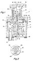
- Figure 1 shows a valve A having a plastic housing B defined by assembled upper and lower plastic housing parts 10, 12.
- Inlet and outlet ports 14, 16 are provided in housing B, and an internal pressure chamber 18 is provided between such ports.
- a gasket 20 is provided for mounting valve A in a known manner with inlet port 14 connected to a pressurized water source, while outlet port 16 is connected to the outlet of a bubbler on a drinking fountain.
- Inlet port 14 comprises a generally cylindrical hole through a wall 24 of housing B, and having an inlet pressure side 26 intersected by inlet port 14 at a relatively sharp circular edge 28.
- An annular guide sleeve 30 extends upwardly from housing wall 24 in outwardly-spaced relationship to inlet port 14 and has an inner cylindrical bore 32 therein.
- valve A The movable components of valve A are shown in a valve closed position on the right side of center line 34 and in a valve open position on the left side of center line 34.
- two different embodiments of a piston and diaphragm assembly are shown on the opposite sides of center line 34.
- Movable poppet means C in the form of an elongated poppet member extends upwardly through inlet port 14.
- An enlarged head 40 on the bottom end portion of poppet C has an external frusto-conical surface facing toward seat 28.
- a screw driver slot 41 is provided in the bottom end of poppet C to facilitate assembly.
- a sleeve member 42 that is separate from piston 44.
- sleeve member 42a is integral with piston 44a.
- Poppet C extends through a central hole 46, 46a in sleeve member 42, 42a, and has a shoulder 50 engaging the bottom end of sleeve member 42, 42a. Poppet C upwardly through central holes in diaphragm 50, 50a and in piston 44, 44a. A threaded upper end portion 52 on poppet C is threaded into a tapped hole in a retainer 54.
- diaphragm 50 On the left of center line 34, an inner peripheral portion of diaphragm 50 is trapped between the upper end of sleeve member 42 and piston 44. The inner peripheral portion of diaphragm 50 is firmly clamped between the upper end of sleeve member 42 and piston 44 by all of these parts being compressed between poppet shoulder 50 and retainer member 54.
- Piston 44a On the right side of center line 34, sleeve member 42a and integral piston 44a are simply gripped between poppet shoulder 50 and retainer member 54 to connect same to poppet C.
- Piston 44a has a circumferential groove 60 in the outer periphery thereof closely receiving an inwardly extending circumferential projection 62 on diaphragm 50a.
- the central portion of diaphragm 50a is of generally cup-like configuration and the diameter of the inner surface of diaphragm projection 62 is somewhat smaller than the diameter of the bottom of recess 60. Therefore, the central cup-like portion of diaphragm 50a ie stretched and grippingly engages piston 44a to retain the diaphragm and piston assembled.
- a diaphragm outer peripheral portion 64, 64a is compressively gripped between housing parts 10, 12 which are welded or otherwise suitably secured together.
- a button actuator guide sleeve 70 extends upwardly from housing part 10 and has a central cylindrical hole 72 therethrough.
- An actuator button 74 is received in hole 72 and has an inwardly extending flange 76 engageable with an outwardly extending flange 78 on retainer member 54.
- First biasing means defined by a coil spring 80 acts on actuator button 74 to normally bias poppet C closed as shown on the right side of center line 34 with the frusto-conical end portion 40 of poppet C engaging seat 28.
- Coil spring 80 surrounds guide sleeve 70 and acts between an upper surface of housing part 10 and an outwardly extending flange 82 on actuator button 74.
- the upper end portion of retainer member 54 has an outer circumferential recess 84 therein receiving one end portion of a coil spring 86 defining second biasing means.
- the opposite end portion of spring 86 acts against the bottom surface of an adjustable stop member 88 threaded into a tapped hole 90 in actuator button 74.
- the upper end portion of retainer member 54 has a screw driver slot therein, the bottom of which is shown at 92 in Figure 1.
- Adjustable stop member 94 also hae a screw driver slot 94 therein.
- Sleeve member 42, 42a has outwardly extending guide projections 101, 102 and 103 thereon closely received within cylindrical bore 32 in guide sleeve 30. This guides movement of poppet C between its open and closed positions, and maintains the center line of poppet C coincidental with the center of inlet port 14.
- first yieldable biasing means 80 biasing actuator button 74 upwardly to pull poppet C to its closed position.
- Manual pushing force applied to button 74 will move same downwardly to the position shown on the left side of center line 34 and this relieves the force of first yieldable biasing means 80 acting on poppet C.
- second yieldable biasing means 86 bias poppet C to its open position shown on the left of center line 34.
- Inlet pressure acting on the bottom end of poppet C tends to move poppet C to its closed position against the biasing force of second yieldable biasing means 86.
- second yieldable biasing means 86 The balance between the biasing force of second yieldable biasing means 86 and the inlet pressure will adjust the open position of poppet C to maintain a regulated flow through outlet port 16. In the event excessive pressure builds up within pressure chamber 18, such pressure acts on piston 44, 44a and diaphragm 50, 50a to move poppet C toward its closed position to further adjust the flow through inlet port 14 for maintaining a substantially uniform flow through outlet port 16. Inlet pressure acting on the end of poppet c and on piston 44, 44a against the biasing force of spring 86 adjusts the relative open position of poppet C for maintaining a substantially uniform flow through outlet port 16.
- the piston and diaphragm arrangement within pressure chamber 18 defines a pressure responsive means connected with poppet C and being responsive to a predetermined excessive pressure in the pressure chamber for overcoming the biasing force of spring 86 to adjust the poppet to a different open position.
- the spring rate of spring 86 and the taper on the frusto-conical end portion of poppet C are matched to produce a flow of approximately 0.43 gallons per minute over a wide range of inlet pressures.
- Outlet port 16 may then be sized to produce such a flow rate when pressure chamber 18 is at approximately 2.4 PSIG. Any deviation in the pressure within pressure chamber 18 is sensed by the pressure responsive means defined by the piston and diaphragm to further adjust the position of poppet C and maintain a regulated flow of water through outlet port 16.
- Housing B and poppet C are preferably molded of a plastic material having sufficient compliance to provide a good seal between seat 28 and the frusto-conical surface on poppet C without requiring any rubber washers or the like.
- plastics are suitable including, but not limited to, polyamides.
Landscapes
- Physics & Mathematics (AREA)
- General Physics & Mathematics (AREA)
- Engineering & Computer Science (AREA)
- Automation & Control Theory (AREA)
- Safety Valves (AREA)
- Control Of Fluid Pressure (AREA)
- Fluid-Pressure Circuits (AREA)
Applications Claiming Priority (2)
| Application Number | Priority Date | Filing Date | Title |
|---|---|---|---|
| US07/318,253 US5022432A (en) | 1989-03-03 | 1989-03-03 | Bubbler valve |
| US318253 | 1989-03-03 |
Publications (2)
| Publication Number | Publication Date |
|---|---|
| EP0385922A2 true EP0385922A2 (de) | 1990-09-05 |
| EP0385922A3 EP0385922A3 (de) | 1991-05-02 |
Family
ID=23237376
Family Applications (1)
| Application Number | Title | Priority Date | Filing Date |
|---|---|---|---|
| EP19900630057 Withdrawn EP0385922A3 (de) | 1989-03-03 | 1990-02-28 | Trinkbrunnen-Ventil |
Country Status (3)
| Country | Link |
|---|---|
| US (1) | US5022432A (de) |
| EP (1) | EP0385922A3 (de) |
| CA (1) | CA2007565A1 (de) |
Cited By (2)
| Publication number | Priority date | Publication date | Assignee | Title |
|---|---|---|---|---|
| EP1261898A4 (de) * | 2000-01-13 | 2004-04-28 | Minebea Co Ltd | Druckausgleichs-flüssigkeitsströmungsregulator mit verringerter länge |
| AU2022374191B1 (en) * | 2022-06-01 | 2023-09-28 | Husqvarna Ab | Pressure reducer |
Families Citing this family (2)
| Publication number | Priority date | Publication date | Assignee | Title |
|---|---|---|---|---|
| US11118691B2 (en) * | 2019-09-30 | 2021-09-14 | G.P. Reeves Inc. | Fluid regulator having integral fluid purge mechanism |
| US12214388B2 (en) | 2022-03-22 | 2025-02-04 | G. P. Reeves, Inc. | Fluid regulator having integral fluid purge mechanism |
Family Cites Families (12)
| Publication number | Priority date | Publication date | Assignee | Title |
|---|---|---|---|---|
| DE488184C (de) * | 1930-04-05 | Knorr Bremse Akt Ges | Druckregler fuer Luftdruckbremsen o. dgl. | |
| US2301031A (en) * | 1939-10-05 | 1942-11-03 | Ferguson Reno | Valve |
| DE869901C (de) * | 1951-11-08 | 1953-03-09 | Willi Daume | Ventil zum selbstaendigen Einsteuern von Hochdruck in eine unter Niederdruck stehende Anlage |
| GB732400A (en) * | 1953-02-16 | 1955-06-22 | Thomas Braddock & Company Ltd | Improvements in gas control valves |
| US3111962A (en) * | 1959-11-16 | 1963-11-26 | Weston Hydraulics Ltd | Pressure regulating valve |
| US3089510A (en) * | 1959-12-08 | 1963-05-14 | Walter O Lum | Removable valve head and seat unit |
| US3310236A (en) * | 1964-05-08 | 1967-03-21 | Acton B Taylor | Drinking fountain arrangement and control valve therefor |
| US3777777A (en) * | 1967-06-02 | 1973-12-11 | Robertshaw Controls Co | Flow control device |
| US3493010A (en) * | 1967-10-25 | 1970-02-03 | H & H Thermostats Inc | Control valve for fluid dispensing system |
| US3730773A (en) * | 1971-06-11 | 1973-05-01 | Royal Brass Manuf Co | Flow volume regulating valve |
| US4275764A (en) * | 1979-06-13 | 1981-06-30 | Berthoud, S.A. | Combination pressure regulator and manual on-off valve |
| US4744387A (en) * | 1987-06-25 | 1988-05-17 | Otteman John H | Fluid pressure regulator |
-
1989
- 1989-03-03 US US07/318,253 patent/US5022432A/en not_active Expired - Fee Related
-
1990
- 1990-01-11 CA CA002007565A patent/CA2007565A1/en not_active Abandoned
- 1990-02-28 EP EP19900630057 patent/EP0385922A3/de not_active Withdrawn
Cited By (3)
| Publication number | Priority date | Publication date | Assignee | Title |
|---|---|---|---|---|
| EP1261898A4 (de) * | 2000-01-13 | 2004-04-28 | Minebea Co Ltd | Druckausgleichs-flüssigkeitsströmungsregulator mit verringerter länge |
| AU2022374191B1 (en) * | 2022-06-01 | 2023-09-28 | Husqvarna Ab | Pressure reducer |
| US12061487B2 (en) | 2022-06-01 | 2024-08-13 | Husqvarna | Pressure reducer |
Also Published As
| Publication number | Publication date |
|---|---|
| CA2007565A1 (en) | 1990-09-03 |
| EP0385922A3 (de) | 1991-05-02 |
| US5022432A (en) | 1991-06-11 |
Similar Documents
| Publication | Publication Date | Title |
|---|---|---|
| US5586569A (en) | Pneumatic pressure regulator | |
| US4226259A (en) | Regulator module | |
| US4730635A (en) | Valve and method | |
| US5383646A (en) | Diaphragm control valve | |
| US4541454A (en) | Pressure regulators | |
| US4336918A (en) | Diaphragm valve with multiple pivot axis valve element | |
| US5595209A (en) | Fluid pressure regulator establishing a stable output fluid pressure | |
| US7475863B2 (en) | Piston for reverse flow diaphragm valve | |
| US5332000A (en) | Low pressure sensitive valve | |
| US4301992A (en) | Diaphragm valve | |
| US6273117B1 (en) | Pressure regulator | |
| US4275764A (en) | Combination pressure regulator and manual on-off valve | |
| JPS6314237B2 (de) | ||
| KR20070048800A (ko) | 조절 밸브 | |
| US8640732B1 (en) | High pressure inlet regulator | |
| HK1006325B (en) | Diaphragm control valve | |
| US5857486A (en) | Pressure relief or back pressure valve | |
| US4453700A (en) | Fluid control valve assembly | |
| US4314582A (en) | Combined pressure-regulator and manual shut-off valve | |
| US6079437A (en) | Diaphragm valve with flow control stem air bleed | |
| US6820641B2 (en) | Internally piloted dome loaded regulator | |
| CN100430852C (zh) | 气动调压器装置 | |
| US3735772A (en) | Water valve apparatus | |
| US4973025A (en) | Metering valve | |
| US5022432A (en) | Bubbler valve |
Legal Events
| Date | Code | Title | Description |
|---|---|---|---|
| PUAI | Public reference made under article 153(3) epc to a published international application that has entered the european phase |
Free format text: ORIGINAL CODE: 0009012 |
|
| AK | Designated contracting states |
Kind code of ref document: A2 Designated state(s): DE FR GB IT |
|
| PUAL | Search report despatched |
Free format text: ORIGINAL CODE: 0009013 |
|
| AK | Designated contracting states |
Kind code of ref document: A3 Designated state(s): DE FR GB IT |
|
| STAA | Information on the status of an ep patent application or granted ep patent |
Free format text: STATUS: THE APPLICATION IS DEEMED TO BE WITHDRAWN |
|
| 18D | Application deemed to be withdrawn |
Effective date: 19911105 |