EP0386306A2 - Circuit permettant d'éviter la formation de gradins dans un bobinage de bande d'un appareil d'enregistrement et/ou de reproduction - Google Patents
Circuit permettant d'éviter la formation de gradins dans un bobinage de bande d'un appareil d'enregistrement et/ou de reproduction Download PDFInfo
- Publication number
- EP0386306A2 EP0386306A2 EP89110346A EP89110346A EP0386306A2 EP 0386306 A2 EP0386306 A2 EP 0386306A2 EP 89110346 A EP89110346 A EP 89110346A EP 89110346 A EP89110346 A EP 89110346A EP 0386306 A2 EP0386306 A2 EP 0386306A2
- Authority
- EP
- European Patent Office
- Prior art keywords
- tape
- recording
- rewound
- motor
- circuit arrangement
- Prior art date
- Legal status (The legal status is an assumption and is not a legal conclusion. Google has not performed a legal analysis and makes no representation as to the accuracy of the status listed.)
- Granted
Links
- 238000004804 winding Methods 0.000 title claims abstract description 16
- 238000000034 method Methods 0.000 claims abstract description 10
- 230000015572 biosynthetic process Effects 0.000 claims abstract description 6
- 230000001960 triggered effect Effects 0.000 abstract description 3
- 238000011156 evaluation Methods 0.000 abstract description 2
- 230000015654 memory Effects 0.000 description 6
- 230000006870 function Effects 0.000 description 2
- 239000000969 carrier Substances 0.000 description 1
- 238000005259 measurement Methods 0.000 description 1
Images

Classifications
-
- G—PHYSICS
- G11—INFORMATION STORAGE
- G11B—INFORMATION STORAGE BASED ON RELATIVE MOVEMENT BETWEEN RECORD CARRIER AND TRANSDUCER
- G11B15/00—Driving, starting or stopping record carriers of filamentary or web form; Driving both such record carriers and heads; Guiding such record carriers or containers therefor; Control thereof; Control of operating function
- G11B15/60—Guiding record carrier
- G11B15/66—Threading; Loading; Automatic self-loading
-
- G—PHYSICS
- G11—INFORMATION STORAGE
- G11B—INFORMATION STORAGE BASED ON RELATIVE MOVEMENT BETWEEN RECORD CARRIER AND TRANSDUCER
- G11B15/00—Driving, starting or stopping record carriers of filamentary or web form; Driving both such record carriers and heads; Guiding such record carriers or containers therefor; Control thereof; Control of operating function
- G11B15/02—Control of operating function, e.g. switching from recording to reproducing
- G11B15/03—Control of operating function, e.g. switching from recording to reproducing by using counters
-
- G—PHYSICS
- G11—INFORMATION STORAGE
- G11B—INFORMATION STORAGE BASED ON RELATIVE MOVEMENT BETWEEN RECORD CARRIER AND TRANSDUCER
- G11B15/00—Driving, starting or stopping record carriers of filamentary or web form; Driving both such record carriers and heads; Guiding such record carriers or containers therefor; Control thereof; Control of operating function
- G11B15/18—Driving; Starting; Stopping; Arrangements for control or regulation thereof
- G11B15/26—Driving record carriers by members acting directly or indirectly thereon
- G11B15/32—Driving record carriers by members acting directly or indirectly thereon through the reels or cores on to which the record carrier is wound
Definitions
- the invention relates to a circuit arrangement for avoiding excessive step formation in the tape winding of a recording and / or reproducing device according to the preamble of claims 1, 2, 3 and 4.
- Answering machines of this type are generally known. However, they have one major disadvantage. During recurring sequences of the announcement, the tape is first moved in the starting direction and then brought back to its starting position by a return. Since this process is repeated very often, steps can occur in the tape wraps in the cassette, with the result, for example, of inadequacies in the tape guide, with the result that the cassette becomes stiff and in extreme cases the tape is damaged.
- the subject of patent application P 37 43 838 provides a counting device which counts the number of announcement cycles.
- the device for controlling the tape transport receives a control signal from the counting device, which first triggers the forwarding and then the returning of the tape, in order only to wind the announcement tape first in the forward and then in the reverse direction.
- an erase circuit is provided which resets the counting device to zero for a new count cycle as soon as the tape has returned to its starting position for an announcement after rewinding.
- the present invention is based on the object, starting from patent application P 37 43 838, to further develop a circuit arrangement such that an excessive step formation of the tape winding can be avoided for any recording and / or reproducing device.
- the circuit arrangement according to claim 1 can be used with any recording and / or playback device, for example answering machine with two magnetic tape memories designed as a cassette or telephone / car telephone with answering machine or information system or dictation machine or magnetic tape device for entertainment electronics, etc.
- any recording and / or playback device for example answering machine with two magnetic tape memories designed as a cassette or telephone / car telephone with answering machine or information system or dictation machine or magnetic tape device for entertainment electronics, etc.
- the entire tape is rewound once in the forward direction and once in the reverse direction, as a result of which any steps in the tape winding that have arisen are eliminated.
- the rewinding process can also, according to patent claim 2, by a motor current indicator and a threshold switch connected to it, or, according to patent claim 3, by a control voltage that can be tapped from a control device of the motor or, according to patent claim 4, by evaluating signals at the output of those used for belt positioning Pulse generators are triggered in a microprocessor. These criteria are a measure of the actual stiffness, while only an empirically determined rule of thumb is used as a triggering criterion in the circuit arrangement according to claim 1.
- the stiffness of the tape winding can be measured in a simple manner with a motor current indicator; however, the circuitry required for this is relatively large.
- the circuitry is less, but the dimensioning must take into account the scatter of the motor constants.
- the circuit complexity can be further reduced if a microprocessor, which is arranged in the recording and / or playback device anyway, can be used, as is the case, for example, for determining the elapsed playing time or tape length and / or remaining time of cassettes or reels of tape-shaped information carriers from DE-PS 26 50 665 is known.
- a counting device Counts the number of calls received without message recording, so the winding and rewinding of the tape reel of the recording cassette can be carried out regardless of the number of announcement cycles.
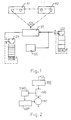
- a counting device Z1 which counts the number of announcement cycles.
- a device ST for controlling the tape transport receives - when a predetermined number of announcement cycles has been reached - a control signal from the counting device Z1, which first triggers the forwarding and then the returning of the tape of the announcement cassette A1, around the tape first in forward and then in reverse direction. The tape is then rewound to its starting position for an announcement.
- the winding through and rewinding of the tape reel of the recording cassette A2 can also be carried out afterwards (or before). Details of the drive, e.g. the control device RE are not shown in FIG. 1.
- the number of announcement cycles, after which both tapes are forwarded and rewound one after the other, is determined empirically and can be 33 for a stenocassette, for example.
- the number of announcement cycles until the tape of the recording and announcement cassette A2 and A1 can be spooled through can also be selected by the user, as will be the case, for example, with a microcassette.
- a second counting device Z2 in the form of an up-counter with an internal reset input (indicated by the dashed line) can also be provided, which is connected to the device ST.
- the two drives for the announcement cassette A1 and the recording cassette A2 are driven by the same motor M (indicated by the chain line in the figure).
- a speech recognition circuit SE (which can be connected to the telecommunication line) is connected to the device ST and the second counting device Z2, with which speech pauses of, for example, more than 8 seconds can be recognized.
- the speech recognition circuit SE can reliably detect when, for example, the caller has hung up and the answering machine is switched off by means of a microprocessor MP and / or device ST arranged in the answering machine and the drive for the recording cassette A2 is stopped. If such a microprocessor MP is present, then this can Take over the function of the two counting devices Z1 and Z2, which can then be omitted.
- a device for automatic pause reduction arranged in the answering machine ensures that there are no pauses of, for example, more than two seconds between the messages of the individual callers.
- the announcement text is usually divided into a message, a message asking the caller to speak and a final announcement.
- the drive of the recording cassette A2 is then driven by the motor M. If the caller hangs up after the final announcement, this is recognized at the latest after 8 seconds by means of speech recognition circuit SE, the tape of the recording cassette A2 is rewound into its starting position and the count of the counting device Z2 is increased by one. In the event that the predetermined number of incoming calls without message recording of, for example, five is exceeded, the tape of the recording cassette A2 is first spooled in the forward and then in the reverse direction (or vice versa) and then rewound into the starting position.
- the starting position can be derived, for example, from the rotational speed of the drive of the recording cassette A2. Furthermore, it is also possible to store the starting position in a digital memory and using a microprocessor MP and / or up / down counter to move back to this starting position, the counting pulses being obtained by scanning one of the windings.
- the counting devices Z1 and Z2 are replaced by a motor current indicator MI, which detects the increasing stiffness of the tape winding or a cassette via the higher motor current. When a predetermined threshold value is exceeded, the cassettes are rewound and rewound into the starting position.
- the motor current indicator MI is connected both to a control device RE and to a threshold switch SWI, which is connected to a microprocessor MP.
- a threshold value circuit SWS is connected to the control device RE and to the motor M and is connected to the microprocessor MP.
- the control voltage that can be tapped at the control device RE triggers the rewinding process of the tapes and the tape is rewound back into the original starting position by means of a microprocessor MP.
- the back EMF of the motor M or the tacho voltage can serve as a threshold.
- the signals at the output of pulse generators used for band positioning can also be evaluated in a microprocessor MP. This determines the respective belt position and the associated target belt speed. When a permissible deviation from the desired tape speed is exceeded, the entire tape for two tapes is rewound simultaneously or successively first in the forward and then in the reverse direction, and after the rewinding process, the tape is rewound back into the original starting position.
Landscapes
- Indexing, Searching, Synchronizing, And The Amount Of Synchronization Travel Of Record Carriers (AREA)
- Digital Magnetic Recording (AREA)
- Television Signal Processing For Recording (AREA)
- Signal Processing For Digital Recording And Reproducing (AREA)
- Control Of Stepping Motors (AREA)
Priority Applications (1)
| Application Number | Priority Date | Filing Date | Title |
|---|---|---|---|
| AT89110346T ATE101448T1 (de) | 1989-03-07 | 1989-06-08 | Schaltungsanordnung zur vermeidung von zu grosser stufenbildung im bandwickel eines aufnahme- und/oder wiedergabegeraetes. |
Applications Claiming Priority (2)
| Application Number | Priority Date | Filing Date | Title |
|---|---|---|---|
| DE3907265 | 1989-03-07 | ||
| DE19893907265 DE3907265A1 (de) | 1987-12-23 | 1989-03-07 | Anrufbeantworter |
Publications (3)
| Publication Number | Publication Date |
|---|---|
| EP0386306A2 true EP0386306A2 (fr) | 1990-09-12 |
| EP0386306A3 EP0386306A3 (fr) | 1991-08-28 |
| EP0386306B1 EP0386306B1 (fr) | 1994-02-09 |
Family
ID=6375704
Family Applications (1)
| Application Number | Title | Priority Date | Filing Date |
|---|---|---|---|
| EP89110346A Expired - Lifetime EP0386306B1 (fr) | 1989-03-07 | 1989-06-08 | Circuit permettant d'éviter la formation de gradins dans un bobinage de bande d'un appareil d'enregistrement et/ou de reproduction |
Country Status (3)
| Country | Link |
|---|---|
| EP (1) | EP0386306B1 (fr) |
| AT (1) | ATE101448T1 (fr) |
| DE (1) | DE58906950D1 (fr) |
Cited By (1)
| Publication number | Priority date | Publication date | Assignee | Title |
|---|---|---|---|---|
| EP1069558A3 (fr) * | 1999-07-14 | 2002-03-13 | Hewlett-Packard Company, A Delaware Corporation | Système informatique à entrainement de bande |
Family Cites Families (2)
| Publication number | Priority date | Publication date | Assignee | Title |
|---|---|---|---|---|
| US4558179A (en) * | 1983-08-31 | 1985-12-10 | T.A.D. Avanti, Inc. | Message playback control system for telephone answering machine |
| DE3743838C2 (de) * | 1987-12-23 | 1994-12-15 | Grundig Emv | Anrufbeantworter |
-
1989
- 1989-06-08 DE DE89110346T patent/DE58906950D1/de not_active Expired - Lifetime
- 1989-06-08 EP EP89110346A patent/EP0386306B1/fr not_active Expired - Lifetime
- 1989-06-08 AT AT89110346T patent/ATE101448T1/de not_active IP Right Cessation
Cited By (1)
| Publication number | Priority date | Publication date | Assignee | Title |
|---|---|---|---|---|
| EP1069558A3 (fr) * | 1999-07-14 | 2002-03-13 | Hewlett-Packard Company, A Delaware Corporation | Système informatique à entrainement de bande |
Also Published As
| Publication number | Publication date |
|---|---|
| EP0386306A3 (fr) | 1991-08-28 |
| DE58906950D1 (de) | 1994-03-24 |
| EP0386306B1 (fr) | 1994-02-09 |
| ATE101448T1 (de) | 1994-02-15 |
Similar Documents
| Publication | Publication Date | Title |
|---|---|---|
| EP0383094B1 (fr) | Procédé et dispositif de lecture de données de navigation d'un disque laser | |
| DE3335078C2 (fr) | ||
| EP0029946A1 (fr) | Dispositions pour enregistrer et retrouver des positions sur des supports d'enregistrements en forme de bande dans un appareil d'enregistrement et/ou de reproduction | |
| DE2443253A1 (de) | System zur ueberwachung von ueber eine fernsprechleitung gewaehlten nummern | |
| DE2140741A1 (de) | Anordnung zur Feststellung des Auf tretens eines Ereignisses | |
| EP0386306B1 (fr) | Circuit permettant d'éviter la formation de gradins dans un bobinage de bande d'un appareil d'enregistrement et/ou de reproduction | |
| DE2832337A1 (de) | Informationsaufzeichnungs- und informationswiedergabegeraet | |
| DE2740934C2 (fr) | ||
| DE3144229A1 (de) | "verfahren und vorrichtung zur magnetischen signalaufzeichnung und -wiedergabe" | |
| DE3121982C2 (de) | Video-Magnetbandgerät mit einer Lade- und Ausladevorrichtung | |
| DE3412735C2 (fr) | ||
| DE1909429B2 (de) | Verfahren zur optimierung der banderregung bei magnetband geraeten mit rotierenden koepfen und geraet zur durchfueh rung des verfahrens | |
| DE1117325B (de) | Laufkontrolleinrichtung fuer Magnetbandgeraete | |
| DE3907265A1 (de) | Anrufbeantworter | |
| EP0212279B1 (fr) | Appareil d'enregistrement magnétique | |
| DE3028691C2 (de) | Magnetbandgerät | |
| DE2840328A1 (de) | Betriebssystem zum gezielten aufrufen von auf elektromotorisch bewegten informationstraegern, insbesondere magnetschichtbaendern, gespeicherten informationsfolgen | |
| DE60028440T2 (de) | Bandtransportvorrichtung | |
| DE2659571A1 (de) | Verfahren zum selbsttaetigen suchen vorgewaehlter tonabschnitte eines magnettonbandes und anordnung zur durchfuehrung dieses verfahrens | |
| DE4224115A1 (de) | Verfahren zur Ermittlung der Spielzeit eines Magnetbandes und Vorrichtung hierfür | |
| EP0054902B1 (fr) | Procédé et appareil pour répondre automatiquement aux appels téléphoniques | |
| DE69028335T2 (de) | Kommunikationsendstelleneinheit mit einer automatischen Antwortfunktion | |
| EP0575388B1 (fr) | Procede et dispositif de rembobinage rapide d'une bande d'enregistrement | |
| DE2505311C3 (de) | Schaltungsanordnung zum raschen Abbremsen eines Magnetbandes | |
| DE3518097C2 (fr) |
Legal Events
| Date | Code | Title | Description |
|---|---|---|---|
| PUAI | Public reference made under article 153(3) epc to a published international application that has entered the european phase |
Free format text: ORIGINAL CODE: 0009012 |
|
| AK | Designated contracting states |
Kind code of ref document: A2 Designated state(s): AT CH DE FR GB LI |
|
| PUAL | Search report despatched |
Free format text: ORIGINAL CODE: 0009013 |
|
| AK | Designated contracting states |
Kind code of ref document: A3 Designated state(s): AT CH DE FR GB LI |
|
| 17P | Request for examination filed |
Effective date: 19920218 |
|
| 17Q | First examination report despatched |
Effective date: 19930719 |
|
| GRAA | (expected) grant |
Free format text: ORIGINAL CODE: 0009210 |
|
| AK | Designated contracting states |
Kind code of ref document: B1 Designated state(s): AT CH DE FR GB LI |
|
| REF | Corresponds to: |
Ref document number: 101448 Country of ref document: AT Date of ref document: 19940215 Kind code of ref document: T |
|
| GBT | Gb: translation of ep patent filed (gb section 77(6)(a)/1977) |
Effective date: 19940208 |
|
| REF | Corresponds to: |
Ref document number: 58906950 Country of ref document: DE Date of ref document: 19940324 |
|
| ET | Fr: translation filed | ||
| PLBE | No opposition filed within time limit |
Free format text: ORIGINAL CODE: 0009261 |
|
| STAA | Information on the status of an ep patent application or granted ep patent |
Free format text: STATUS: NO OPPOSITION FILED WITHIN TIME LIMIT |
|
| 26N | No opposition filed | ||
| REG | Reference to a national code |
Ref country code: GB Ref legal event code: 746 Effective date: 19950612 |
|
| REG | Reference to a national code |
Ref country code: CH Ref legal event code: PFA Free format text: GRUNDIG E.M.V. ELEKTRO- MECHANISCHE VERSUCHSANSTALT MAX GRUNDIG GMBH & CO. KG |
|
| REG | Reference to a national code |
Ref country code: FR Ref legal event code: D6 |
|
| REG | Reference to a national code |
Ref country code: FR Ref legal event code: CD |
|
| REG | Reference to a national code |
Ref country code: CH Ref legal event code: PFA Free format text: GRUNDIG E.M.V. ELEKTRO- MECHANISCHE VERSUCHSANSTALT MAX GRUNDIG GMBH & CO. KG TRANSFER- GRUNDIG AG |
|
| REG | Reference to a national code |
Ref country code: FR Ref legal event code: TP |
|
| REG | Reference to a national code |
Ref country code: GB Ref legal event code: IF02 |
|
| REG | Reference to a national code |
Ref country code: CH Ref legal event code: PUE Owner name: GRUNDIG MULTIMEDIA B.V. Free format text: GRUNDIG AG#KURGARTENSTRASSE 37#D-90762 FUERTH (DE) -TRANSFER TO- GRUNDIG MULTIMEDIA B.V.#DE BOELELAAN 7 OFF. I 2 HG#1083HJ AMSTERDAM (NL) |
|
| REG | Reference to a national code |
Ref country code: GB Ref legal event code: 732E |
|
| REG | Reference to a national code |
Ref country code: FR Ref legal event code: TP |
|
| PGFP | Annual fee paid to national office [announced via postgrant information from national office to epo] |
Ref country code: CH Payment date: 20080627 Year of fee payment: 20 |
|
| PGFP | Annual fee paid to national office [announced via postgrant information from national office to epo] |
Ref country code: AT Payment date: 20080624 Year of fee payment: 20 |
|
| PGFP | Annual fee paid to national office [announced via postgrant information from national office to epo] |
Ref country code: DE Payment date: 20080624 Year of fee payment: 20 |
|
| PGFP | Annual fee paid to national office [announced via postgrant information from national office to epo] |
Ref country code: FR Payment date: 20080626 Year of fee payment: 20 |
|
| PGFP | Annual fee paid to national office [announced via postgrant information from national office to epo] |
Ref country code: GB Payment date: 20080630 Year of fee payment: 20 |
|
| REG | Reference to a national code |
Ref country code: CH Ref legal event code: PL |
|
| REG | Reference to a national code |
Ref country code: GB Ref legal event code: PE20 Expiry date: 20090607 |
|
| PG25 | Lapsed in a contracting state [announced via postgrant information from national office to epo] |
Ref country code: GB Free format text: LAPSE BECAUSE OF EXPIRATION OF PROTECTION Effective date: 20090607 |