EP0386355A1 - Kraftschrauber - Google Patents
Kraftschrauber Download PDFInfo
- Publication number
- EP0386355A1 EP0386355A1 EP89306776A EP89306776A EP0386355A1 EP 0386355 A1 EP0386355 A1 EP 0386355A1 EP 89306776 A EP89306776 A EP 89306776A EP 89306776 A EP89306776 A EP 89306776A EP 0386355 A1 EP0386355 A1 EP 0386355A1
- Authority
- EP
- European Patent Office
- Prior art keywords
- engaging
- threaded
- holding
- power wrench
- threaded member
- Prior art date
- Legal status (The legal status is an assumption and is not a legal conclusion. Google has not performed a legal analysis and makes no representation as to the accuracy of the status listed.)
- Withdrawn
Links
- 230000015572 biosynthetic process Effects 0.000 claims description 7
- 238000005755 formation reaction Methods 0.000 claims 4
- 235000012054 meals Nutrition 0.000 claims 1
- 238000006243 chemical reaction Methods 0.000 description 4
- 238000010276 construction Methods 0.000 description 2
- 239000012530 fluid Substances 0.000 description 2
- 230000004048 modification Effects 0.000 description 2
- 238000012986 modification Methods 0.000 description 2
- 230000000295 complement effect Effects 0.000 description 1
- 238000006073 displacement reaction Methods 0.000 description 1
- 238000000034 method Methods 0.000 description 1
Images


Classifications
-
- B—PERFORMING OPERATIONS; TRANSPORTING
- B25—HAND TOOLS; PORTABLE POWER-DRIVEN TOOLS; MANIPULATORS
- B25B—TOOLS OR BENCH DEVICES NOT OTHERWISE PROVIDED FOR, FOR FASTENING, CONNECTING, DISENGAGING OR HOLDING
- B25B21/00—Portable power-driven screw or nut setting or loosening tools; Attachments for drilling apparatus serving the same purpose
- B25B21/004—Portable power-driven screw or nut setting or loosening tools; Attachments for drilling apparatus serving the same purpose of the ratchet type
- B25B21/005—Portable power-driven screw or nut setting or loosening tools; Attachments for drilling apparatus serving the same purpose of the ratchet type driven by a radially acting hydraulic or pneumatic piston
Definitions
- the present invention relates to a power wrench for tightening and loosening of threaded connectors including two threaded members, such as for example a bolt and a nut, or a stud and a nut, etc..
- Power operated wrenches of the above-mentioned general type are known in the art.
- a threaded connector for example a nut
- the other threaded member of the same threaded connector for example a bolt or a stud turns together with the nut.
- this phenomenon is highly undesirable. It creates tremendous problems for example in the case when a stud is screwed into a blind hole in a bottom half of a flange, and the user does not want the stud to bottom out since later on this would cause tremendous difficulties when trying to get the stud out of the bottom shell.
- the present invention seeks to provide a power wrench which avoids the disadvantages of the prior art.
- the present invention seeks to provide a power wrench which during turning of one threaded member of a threaded connector for its fastening or loosening, prevents turning of the other threaded member of the same threaded connector.
- a power wrench which has drive means, engaging means for engaging one threaded member of a threaded connector and drivable by the drive means so as to turn the one threaded member in the direction of the drive means, a housing, and in addition to this holding means which hold the other threaded member of the same threaded connector during turning the one threaded member of the same.
- the other threaded member of the threaded connector is no longer permitted to turn during turning of the one member of the threaded connector.
- problems no longer arise from turning of the other threaded member and no additional backup wrench is needed for tightening or loosening a threaded connector.
- a power wrench for example a fluid-operated wrench in accordance with the present invention has a housing which can be subdivided into two housing portions 1 and 2 which adjoin one another over a dividing plane 3.
- the housing can be an integral structure as well.
- the housing 1, 2 accommodates a drive which is formed as a cylinder-piston unit.
- the cylinder-piston unit is provided with a cylinder 4 which forms an inner chamber, and a piston 5 which is movable in the inner chamber of the cylinder 4 under the action of fluid, for example a hydraulic or pneumatic medium, admitted into the inner chamber in the respective side of the piston 5.
- the piston 5 is connected with a piston rod 6 which extends in an axial direction beyond the housing portion 1 into the housing portion 2.
- the engaging unit includes a link 7 having a central opening and an engaging member, which is formed for example as a ratchet wheel 8, arranged in the opening of the link 7 and provided with an engaging formation.
- the engaging formation is a hexagonal opening 9 (with a central axis B) which can engage for example a hexagonal head of a nut.
- the engaging member is turnably inserted into the link 7.
- a pawl 10 is connected with the link 7 in a known manner, for example pivotably as disclosed for example in US-A-4,079,641.
- the ratchet wheel 8 and the pawl 10 are provided with interengaging projections and grooves which are formed so that when the link 7 is turned in a working direction, the projections of the pawl 10 engage in the grooves of the ratchet wheel 8, while when the link 7 is turned in an opposite direction, the projections of the pawl 10 slip over the projections of the ratchet wheel 8 without turning the latter as disclosed in the above-mentioned patent.
- Two link plates 11′ and 11 ⁇ are arranged one on each of the opposite sides of the link 7 so as to sandwich the link therebetween.
- the link 7 has an upper end 12 which is pivotally connected with a free end of the piston rod 6, for example by means of a pin as shown which is pivotally and slidingly guided in an opening 13 at the free end of the piston rod 6.
- the housing portion 1 is round or square, while the housing portion 2 is formed by two housing plates 2′ and 2 ⁇ .
- Link plates 11′ and 11 ⁇ are arranged between the housing plates 2′ and 2 ⁇ and immovably connected with one another.
- the connection is formed by a pin 14 which extends through openings 15 in the housing plates 2′ and 2 ⁇ and openings 16 in the link plates 11′ and 11 ⁇ .
- Projections 17 of the link plates 11′ and 11 ⁇ engage in grooves 18 of the housing plates 2′ and 2 ⁇ .
- a reaction member 19 is further provided in the power wrench.
- the reaction member 19 is attachable to the link 7 and the link plates 11′ and 11 ⁇ by means of two pins 20 and 21.
- the reaction member 19 also has an opening 22 for receiving the pin 14.
- the power wrench constructed in accordance with the above presented description substantially corresponds to the power wrench disclosed in EP-A-89301565.1. It is to be understood, however, that it can be made somewhat differently as well.
- the power wrench is provided with a holding element which is iden tified as a whole by reference numeral 23.
- the holding element has one end provided with an opening 24.
- the holding element 23 is connected with the housing 1, 2 by fitting its one end with the opening 24 on the pin 14.
- the opposite free end of the holding element 23 is provided with a holding formation which can be formed as a hexagonal opening 25.
- the holding element 23 can engage with its opening 25 a bolt head or the like, when the engaging opening 9 engages a nut of the same threaded connector.
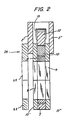
- the holding element 23 is formed as a link which is somewhat similar to the link 7.
- Figure 2 clearly shows that the link 7 and the element 23 extend parallel to one another and very close to one another.
- This Figure also shows that the opening 9 of the ratchet wheel 8, which together with the link 7 forms the engaging unit, is coaxial with the opening 25 of the holding element 23.
- the power wrench in accordance with the present invention operates in the following manner:
- the opening 9 of the engaging unit is engaged with a nut to be turned, the reaction member 19 is brought to abutment against a neighbouring object and the opening 25 of the holding element 23 is engaged with a bolt head of the same threaded connector.
- a fluid under pressure is supplied to the inner chamber of the cylinder 4 during a working stroke, so that the piston 5 is moved and the piston rod 6 is extended, or in other words displaced to the left of the housing (as shown in Figure 1).
- the link 7 turns counterclockwise, thus turning the pawl 10 which with its projections engaging into the grooves of the ratchet wheel 8 turns the engaging member with the opening 9.
- the wheel 8 turns the nut of the threaded connector about the axis B in a counterclockwise direction. During this turning, the opening 25 of the holding element 23 is in engagement with the bolt head and therefore the bolt head of the same threaded connector cannot turn together with the nut.
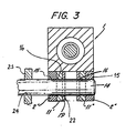
- one end of the pin 14 extends laterally beyond the housing, and the holding element 23 is supported on this projecting end of the pin 14.
- the holding element 23 can be fixedly arranged on the end of the pin 14, but, on the other hand, it can slide over the pin 14 so as to adjust the distance between the engaging unit 7, 8 which engages the nut and the holding element 23 which engages the bolt head, depending on the actual distance between the nut and the bolt head.
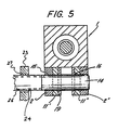
- the laterally extending end of the pin 14 can be provided with an outer thread 26, while the opening 24 of the holding element 23 can be provided with a complementary inner thread 27.
- the holding element 23 can be turned on the pin 14 as a result of interengagement of the threads 26, 27 so as to adjust the distance between the holding element 23 and the engaging unit 7, 8, depending on the actual distance between the nut and bolt head.
Landscapes
- Engineering & Computer Science (AREA)
- Mechanical Engineering (AREA)
- Details Of Spanners, Wrenches, And Screw Drivers And Accessories (AREA)
Applications Claiming Priority (2)
| Application Number | Priority Date | Filing Date | Title |
|---|---|---|---|
| US32207489A | 1989-03-10 | 1989-03-10 | |
| US322074 | 1989-03-10 |
Publications (1)
| Publication Number | Publication Date |
|---|---|
| EP0386355A1 true EP0386355A1 (de) | 1990-09-12 |
Family
ID=23253300
Family Applications (1)
| Application Number | Title | Priority Date | Filing Date |
|---|---|---|---|
| EP89306776A Withdrawn EP0386355A1 (de) | 1989-03-10 | 1989-07-04 | Kraftschrauber |
Country Status (2)
| Country | Link |
|---|---|
| EP (1) | EP0386355A1 (de) |
| JP (1) | JPH02237774A (de) |
Cited By (6)
| Publication number | Priority date | Publication date | Assignee | Title |
|---|---|---|---|---|
| US5939232A (en) * | 1996-07-03 | 1999-08-17 | E. I. Du Pont De Nemours And Company | Photosensitive elements and their process of use |
| US5965321A (en) * | 1997-09-25 | 1999-10-12 | E. U. Du Pont De Nemours And Company | Peel-apart photosensitive elements and their process of use |
| US6001532A (en) * | 1997-09-25 | 1999-12-14 | E.I. Dupont De Nemours And Company | Peel-apart photosensitive elements and their process of use |
| US6100006A (en) * | 1999-08-19 | 2000-08-08 | E. I. Du Pont De Nemours And Company | Peel-apart photosensitive elements and their process of use |
| ES2349981A1 (es) * | 2006-09-12 | 2011-01-14 | Unex Corporation | Herramienta de torsion para apretar y aflojar conexiones, y metodo para apretar y aflojar las mismas. |
| GB2517026A (en) * | 2013-05-21 | 2015-02-11 | Hire Torque Ltd | Torque wrench |
Families Citing this family (1)
| Publication number | Priority date | Publication date | Assignee | Title |
|---|---|---|---|---|
| US7497147B2 (en) * | 2006-09-12 | 2009-03-03 | Unex Corporation | Torque tool for tightening or loosening connections, and method of tightening or loosening the same |
Citations (2)
| Publication number | Priority date | Publication date | Assignee | Title |
|---|---|---|---|---|
| US3097551A (en) * | 1963-07-16 | schmitt | ||
| US3198040A (en) * | 1963-01-14 | 1965-08-03 | Imp Eastman Corp | Wrench |
Family Cites Families (2)
| Publication number | Priority date | Publication date | Assignee | Title |
|---|---|---|---|---|
| JPS5127520A (en) * | 1974-08-29 | 1976-03-08 | Hideo Kawasaki | Mamekariki |
| JPS60263674A (ja) * | 1984-06-07 | 1985-12-27 | 東京電力株式会社 | ボルト自動締結装置 |
-
1989
- 1989-07-04 EP EP89306776A patent/EP0386355A1/de not_active Withdrawn
- 1989-07-04 JP JP17269989A patent/JPH02237774A/ja active Pending
Patent Citations (2)
| Publication number | Priority date | Publication date | Assignee | Title |
|---|---|---|---|---|
| US3097551A (en) * | 1963-07-16 | schmitt | ||
| US3198040A (en) * | 1963-01-14 | 1965-08-03 | Imp Eastman Corp | Wrench |
Cited By (8)
| Publication number | Priority date | Publication date | Assignee | Title |
|---|---|---|---|---|
| US5939232A (en) * | 1996-07-03 | 1999-08-17 | E. I. Du Pont De Nemours And Company | Photosensitive elements and their process of use |
| US5965321A (en) * | 1997-09-25 | 1999-10-12 | E. U. Du Pont De Nemours And Company | Peel-apart photosensitive elements and their process of use |
| US6001532A (en) * | 1997-09-25 | 1999-12-14 | E.I. Dupont De Nemours And Company | Peel-apart photosensitive elements and their process of use |
| US6071669A (en) * | 1997-09-25 | 2000-06-06 | E. I. Du Pont De Nemours And Company | Peel-apart photosensitive elements and their process of use |
| US6100006A (en) * | 1999-08-19 | 2000-08-08 | E. I. Du Pont De Nemours And Company | Peel-apart photosensitive elements and their process of use |
| ES2349981A1 (es) * | 2006-09-12 | 2011-01-14 | Unex Corporation | Herramienta de torsion para apretar y aflojar conexiones, y metodo para apretar y aflojar las mismas. |
| GB2517026A (en) * | 2013-05-21 | 2015-02-11 | Hire Torque Ltd | Torque wrench |
| GB2517026B (en) * | 2013-05-21 | 2020-02-26 | Hire Torque Ltd | Torque wrench |
Also Published As
| Publication number | Publication date |
|---|---|
| JPH02237774A (ja) | 1990-09-20 |
Similar Documents
| Publication | Publication Date | Title |
|---|---|---|
| US4825730A (en) | Fluid operated wrench | |
| US6260444B1 (en) | Power tool | |
| US6152243A (en) | Universal torque power tool | |
| USRE33951E (en) | Fluid operated wrench | |
| US5499558A (en) | Fluid operated tool for elongating and relaxing a threaded connector | |
| US5398574A (en) | Fluid operating tool | |
| EP1151826B1 (de) | Verfahren und Vorrichtung zum Anziehen von Schraubverbindungen | |
| USRE40765E1 (en) | Fluid-operated power tool | |
| US5140874A (en) | Fluid-operated wrench | |
| US5005447A (en) | Torque wrench | |
| EP0386355A1 (de) | Kraftschrauber | |
| US4706526A (en) | Fluid operated wrench | |
| US20030126956A1 (en) | Fluid-operated torque wrench | |
| US5029497A (en) | Continuous ratchet drive | |
| EP0504331B1 (de) | Hydraulisch betriebener schraubenschlüssel | |
| US6105472A (en) | Fluid-operated tool | |
| EP0324050A1 (de) | Kraftschrauber | |
| HK1032931A (en) | Universal torque power tool | |
| HK1030390B (en) | Power tool |
Legal Events
| Date | Code | Title | Description |
|---|---|---|---|
| PUAI | Public reference made under article 153(3) epc to a published international application that has entered the european phase |
Free format text: ORIGINAL CODE: 0009012 |
|
| AK | Designated contracting states |
Kind code of ref document: A1 Designated state(s): AT BE CH DE ES FR GB GR IT LI LU NL SE |
|
| STAA | Information on the status of an ep patent application or granted ep patent |
Free format text: STATUS: THE APPLICATION IS DEEMED TO BE WITHDRAWN |
|
| 18D | Application deemed to be withdrawn |
Effective date: 19910313 |