EP0386439A2 - Palpeur d'angle pour déterminer la rotation d'un arbre - Google Patents
Palpeur d'angle pour déterminer la rotation d'un arbre Download PDFInfo
- Publication number
- EP0386439A2 EP0386439A2 EP19900101665 EP90101665A EP0386439A2 EP 0386439 A2 EP0386439 A2 EP 0386439A2 EP 19900101665 EP19900101665 EP 19900101665 EP 90101665 A EP90101665 A EP 90101665A EP 0386439 A2 EP0386439 A2 EP 0386439A2
- Authority
- EP
- European Patent Office
- Prior art keywords
- angle sensor
- signal
- shaft
- steering column
- transmitter
- Prior art date
- Legal status (The legal status is an assumption and is not a legal conclusion. Google has not performed a legal analysis and makes no representation as to the accuracy of the status listed.)
- Granted
Links
- 238000005259 measurement Methods 0.000 claims abstract description 16
- 239000004020 conductor Substances 0.000 abstract description 4
- 238000010079 rubber tapping Methods 0.000 description 3
- 230000005540 biological transmission Effects 0.000 description 2
- 238000010276 construction Methods 0.000 description 1
- 238000011161 development Methods 0.000 description 1
- 230000018109 developmental process Effects 0.000 description 1
- 238000010586 diagram Methods 0.000 description 1
- 238000007789 sealing Methods 0.000 description 1
- 238000000926 separation method Methods 0.000 description 1
Images
Classifications
-
- G—PHYSICS
- G01—MEASURING; TESTING
- G01B—MEASURING LENGTH, THICKNESS OR SIMILAR LINEAR DIMENSIONS; MEASURING ANGLES; MEASURING AREAS; MEASURING IRREGULARITIES OF SURFACES OR CONTOURS
- G01B7/00—Measuring arrangements characterised by the use of electric or magnetic techniques
- G01B7/30—Measuring arrangements characterised by the use of electric or magnetic techniques for measuring angles or tapers; for testing the alignment of axes
-
- B—PERFORMING OPERATIONS; TRANSPORTING
- B62—LAND VEHICLES FOR TRAVELLING OTHERWISE THAN ON RAILS
- B62D—MOTOR VEHICLES; TRAILERS
- B62D15/00—Steering not otherwise provided for
- B62D15/02—Steering position indicators ; Steering position determination; Steering aids
-
- G—PHYSICS
- G01—MEASURING; TESTING
- G01D—MEASURING NOT SPECIALLY ADAPTED FOR A SPECIFIC VARIABLE; ARRANGEMENTS FOR MEASURING TWO OR MORE VARIABLES NOT COVERED IN A SINGLE OTHER SUBCLASS; TARIFF METERING APPARATUS; MEASURING OR TESTING NOT OTHERWISE PROVIDED FOR
- G01D5/00—Mechanical means for transferring the output of a sensing member; Means for converting the output of a sensing member to another variable where the form or nature of the sensing member does not constrain the means for converting; Transducers not specially adapted for a specific variable
- G01D5/12—Mechanical means for transferring the output of a sensing member; Means for converting the output of a sensing member to another variable where the form or nature of the sensing member does not constrain the means for converting; Transducers not specially adapted for a specific variable using electric or magnetic means
- G01D5/14—Mechanical means for transferring the output of a sensing member; Means for converting the output of a sensing member to another variable where the form or nature of the sensing member does not constrain the means for converting; Transducers not specially adapted for a specific variable using electric or magnetic means influencing the magnitude of a current or voltage
- G01D5/16—Mechanical means for transferring the output of a sensing member; Means for converting the output of a sensing member to another variable where the form or nature of the sensing member does not constrain the means for converting; Transducers not specially adapted for a specific variable using electric or magnetic means influencing the magnitude of a current or voltage by varying resistance
- G01D5/165—Mechanical means for transferring the output of a sensing member; Means for converting the output of a sensing member to another variable where the form or nature of the sensing member does not constrain the means for converting; Transducers not specially adapted for a specific variable using electric or magnetic means influencing the magnitude of a current or voltage by varying resistance by relative movement of a point of contact or actuation and a resistive track
- G01D5/1655—Mechanical means for transferring the output of a sensing member; Means for converting the output of a sensing member to another variable where the form or nature of the sensing member does not constrain the means for converting; Transducers not specially adapted for a specific variable using electric or magnetic means influencing the magnitude of a current or voltage by varying resistance by relative movement of a point of contact or actuation and a resistive track more than one point of contact or actuation on one or more tracks
-
- G—PHYSICS
- G01—MEASURING; TESTING
- G01D—MEASURING NOT SPECIALLY ADAPTED FOR A SPECIFIC VARIABLE; ARRANGEMENTS FOR MEASURING TWO OR MORE VARIABLES NOT COVERED IN A SINGLE OTHER SUBCLASS; TARIFF METERING APPARATUS; MEASURING OR TESTING NOT OTHERWISE PROVIDED FOR
- G01D2205/00—Indexing scheme relating to details of means for transferring or converting the output of a sensing member
- G01D2205/20—Detecting rotary movement
- G01D2205/26—Details of encoders or position sensors specially adapted to detect rotation beyond a full turn of 360°, e.g. multi-rotation
-
- G—PHYSICS
- G01—MEASURING; TESTING
- G01D—MEASURING NOT SPECIALLY ADAPTED FOR A SPECIFIC VARIABLE; ARRANGEMENTS FOR MEASURING TWO OR MORE VARIABLES NOT COVERED IN A SINGLE OTHER SUBCLASS; TARIFF METERING APPARATUS; MEASURING OR TESTING NOT OTHERWISE PROVIDED FOR
- G01D2205/00—Indexing scheme relating to details of means for transferring or converting the output of a sensing member
- G01D2205/20—Detecting rotary movement
- G01D2205/28—The target being driven in rotation by additional gears
Definitions
- the invention is based on an angle sensor according to the preamble of the main claim.
- a signal transmitter is arranged concentrically around the steering column and delivers a measurement signal that is repeated every 360 °.
- signal generators that generate fine and coarse signals.
- the two signal generators are then arranged at different points on the steering gear, or are located next to the steering column and the rotary movement is transmitted from the steering column to the signal generators with the aid of toothed belts.
- the angle sensor has a more complex construction. Due to the additional transmission elements or the separate tapping points of the angle of rotation, the measurement signals have measurement errors.
- the angle sensor according to the invention with the characterizing features of claim 1 or 4 has the advantage that the sensor builds very compact. It can be attached to the steering column in a very simple manner. The coarse and fine signals are tapped at almost the same point without intermediate linkage. The element mechanically tapping the rotary movement on the steering column actuates both the coarse and the fine signal transmitter. A high degree of accuracy is possible over the entire turning range of the steering column. Due to the separation into a coarse and a fine signal, the electrical signal only needs to be recorded with medium resolution. As a result, the transmission of the signal in the vehicle is not particularly susceptible to interference, and in the case of voltage-analog signal output, it is possible to use inexpensive analog-digital converters which are common in motor vehicles.
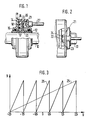
- FIG. 1 shows a section through an angle sensor arranged on a steering column
- FIG. 2 shows a partial view of the coarse signal transmitter
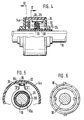
- Figure 6 shows a section in viewing direction VI.
- 10 denotes the steering column of a motor vehicle, not shown, on which to tap a measurement signal a tap element 12 is attached.
- the tap element 12 has a flange 13 which projects into the interior of a housing 14 which is U-shaped in cross section and radially encompasses the entire steering column 10.
- the housing 14 is rotatably mounted on the tap element 12 and its interior is sealed with sealing rings 15, so that no dirt can penetrate into the interior of the housing 14.
- an encoder 16 is arranged on one end face of the flange 13.
- the transmitter 16 is designed as a potentiometer, but other signal transmitters can also be used.
- the grinder 17 of the potentiometer 16 is fastened to the end face of the flange 13, and the associated conductor tracks 18 are fastened to the facing inner wall of the housing 14.
- a spiral guide groove 19 is formed, in which a guide pin 20 of the transmitter 21 generating the coarse signal slides.
- the encoder 21 is a linear potentiometer shown in more detail in FIG. 2.
- the potentiometer 21 is moved along a column 22 aligned radially to the steering column 10.
- the grinder 23 is moved along a conductor track 24 attached to the column 22 with the aid of a dovetail-like holder.
- a cable 27 is arranged on the housing 14 in order to derive the measurement signals from both transmitters 16, 21.
- the steering column 10 and the tapping element 12 carry out the same rotary movement.
- the pin 20 of the signal transmitter 21 slides in the guide groove 19. In the starting position, the pin 20 is in the middle of the length of the guide groove 19 and can be deflected in both directions of rotation by ⁇ 2.5 turns of the steering column 10. This turning range is the normal turning angle aimed at in steering.
- the number of revolutions U of the steering column 10 is plotted on the X axis and the size of the measurement signal R on the Y axis.
- the starting position is labeled 0 on the X axis.
- the measurement signal 25 generated by the signal generator 21 ver runs in the optimal state from -2.5 to +2.5 revolutions continuously linear.
- the measurement signal 26 generated by the signal generator 16 is repeated after each revolution of 360 °.
- the signal generator 21 is arranged in such a way that the measurement signal begins at the maximum deflection of the wheels, ie at a revolution of -2.5 revolutions. Due to the width of the grinders and the physical conditions prevailing in the edge areas, the measurement curve 26 already reaches the maximum just before a full revolution, ie before the revolution value of -1.5 revolutions, and falls steeply to the minimum at the value of somewhat more than - 1.5 turns. At this revolution value, it then begins to rise again.
- the so-called fine signal 26 of the signal generator 16 and the so-called coarse signal 25 of the signal generator 21 an exact determination of the angular position of the steering column 10 is possible.
- the embodiment according to FIG. 4 differs from that according to FIG. 1 in particular by the configuration of the signal transmitter 21.
- a parallel to the Steering column 10 extending coil 30, d. H. a thread is formed.
- the tap element 12a must be extended by the length of the thread 30 compared to FIG. 1.
- a counter thread 31 engages in the thread 30, which is arranged in a ring around the tap element 12 a and to which a holding part 32 is fastened.
- the holding part 32 is guided by two shoulders 33 attached to the housing 14a.
- a linear potentiometer 34 is arranged on the holding part 32, the slider 35 of which slides along the conductor track 36 arranged on the inner wall of the housing.
- the mode of operation and the measurement signal acquisition correspond to that of the exemplary embodiment according to FIG. 1.
Landscapes
- Physics & Mathematics (AREA)
- General Physics & Mathematics (AREA)
- Engineering & Computer Science (AREA)
- Chemical & Material Sciences (AREA)
- Combustion & Propulsion (AREA)
- Transportation (AREA)
- Mechanical Engineering (AREA)
- Measurement Of Length, Angles, Or The Like Using Electric Or Magnetic Means (AREA)
- Length Measuring Devices With Unspecified Measuring Means (AREA)
- Transmission And Conversion Of Sensor Element Output (AREA)
Applications Claiming Priority (2)
| Application Number | Priority Date | Filing Date | Title |
|---|---|---|---|
| DE3907442 | 1989-03-08 | ||
| DE3907442A DE3907442A1 (de) | 1989-03-08 | 1989-03-08 | Winkelsensor zur bestimmung der drehung einer welle |
Publications (3)
| Publication Number | Publication Date |
|---|---|
| EP0386439A2 true EP0386439A2 (fr) | 1990-09-12 |
| EP0386439A3 EP0386439A3 (fr) | 1991-06-05 |
| EP0386439B1 EP0386439B1 (fr) | 1993-11-18 |
Family
ID=6375809
Family Applications (1)
| Application Number | Title | Priority Date | Filing Date |
|---|---|---|---|
| EP90101665A Expired - Lifetime EP0386439B1 (fr) | 1989-03-08 | 1990-01-27 | Palpeur d'angle pour déterminer la rotation d'un arbre |
Country Status (3)
| Country | Link |
|---|---|
| EP (1) | EP0386439B1 (fr) |
| JP (1) | JP2974717B2 (fr) |
| DE (2) | DE3907442A1 (fr) |
Cited By (14)
| Publication number | Priority date | Publication date | Assignee | Title |
|---|---|---|---|---|
| EP0460417A1 (fr) * | 1990-06-07 | 1991-12-11 | Robert Bosch Gmbh | Capteur inductif de l'angle pour déterminer la rotation d'un arbre |
| DE4115244A1 (de) * | 1991-05-10 | 1992-11-12 | Bayerische Motoren Werke Ag | Winkelsensor zur bestimmung der drehlage einer welle |
| DE4142457A1 (de) * | 1991-12-20 | 1993-06-24 | Bayerische Motoren Werke Ag | Verfahren zur bestimmung der drehlage einer lenkwelle von kraftfahrzeugen |
| DE4231624A1 (de) * | 1992-09-22 | 1994-03-24 | Siedle Horst Kg | Positionssensor für Bewegungsabläufe |
| FR2710406A1 (fr) * | 1993-09-20 | 1995-03-31 | Bosch Gmbh Robert | Transmetteur d'angle de rotation. |
| US5615581A (en) * | 1993-03-05 | 1997-04-01 | Cordioli; Sergio | Remotely controlled device for rotating the steering-wheel of a motor vehicle and then taking it back to the starting position |
| EP0793076A1 (fr) * | 1996-02-27 | 1997-09-03 | MAGNETI MARELLI S.p.A. | Dispositif de détection de la position de l'arbre de sortie d'une actionneur |
| DE19638911A1 (de) * | 1996-09-23 | 1998-03-26 | Teves Gmbh Alfred | Drehwinkelsensor mit integrierter Umdrehungserkennung |
| EP0893672A1 (fr) * | 1997-07-25 | 1999-01-27 | Sc2N | Capteur d'angle pour véhicule automobile, notamment pour arbre de direction |
| EP0983929A1 (fr) * | 1998-09-03 | 2000-03-08 | Valeo Electronique | Capteur d'angle absolue entrainé par une couronne liée au volant |
| DE4142415C2 (de) * | 1991-12-20 | 2000-11-16 | Bayerische Motoren Werke Ag | Verfahren zur Bestimmung der Drehlage einer Lenkwelle von Kraftfahrzeugen |
| EP1061343A1 (fr) * | 1999-06-15 | 2000-12-20 | Hella KG Hueck & Co. | Capteur de position pour un véhicule |
| WO2013056960A1 (fr) * | 2011-10-21 | 2013-04-25 | Robert Bosch Gmbh | Ensemble capteur |
| CN107340002A (zh) * | 2017-06-28 | 2017-11-10 | 西安微电机研究所 | 一种小惯量有限角度传感器 |
Families Citing this family (21)
| Publication number | Priority date | Publication date | Assignee | Title |
|---|---|---|---|---|
| JPH0464709U (fr) * | 1990-10-17 | 1992-06-03 | ||
| DE4137092C2 (de) * | 1991-11-12 | 1995-05-24 | Walcher Mestechnik Gmbh | Verfahren zum Messen von Winkeln von mehr als 360 DEG |
| DE4221186C2 (de) * | 1992-06-27 | 1994-07-28 | Bosch Gmbh Robert | Verfahren zur Ermittlung der Referenz- und der Versorgungsspannung in einer Recheneinrichtung |
| DE19703525C2 (de) * | 1997-01-31 | 2000-05-25 | Walcher Mestechnik Gmbh | Vorrichtung zur Positionierung einer Welle |
| DE19712869A1 (de) * | 1997-03-27 | 1998-10-01 | Itt Mfg Enterprises Inc | Lenkwinkelsensorsystem mit erhöhter Redundanz |
| KR100396300B1 (ko) * | 1997-12-30 | 2003-11-28 | 주식회사 만도 | 차량 조향시스템의 절대각 감지센서 |
| DE19816683A1 (de) * | 1998-04-15 | 1999-10-21 | Linde Ag | Vorrichtung zum Erfassen der Drehstellung eines Lenkrads |
| DE19823903A1 (de) * | 1998-05-28 | 1999-12-02 | Sensor Instr Gmbh | Vorrichtung zum gleichzeitigen Messen eines an einer Welle wirksamen Drehmoments sowie des Drehwinkels der Welle |
| DE19828513A1 (de) * | 1998-06-26 | 1999-12-30 | Zahnradfabrik Friedrichshafen | Elektrisch unterstützte Hilfskraftlenkung für Kraftfahrzeuge |
| DE19855064B4 (de) * | 1998-11-28 | 2004-07-01 | Leopold Kostal Gmbh & Co Kg | Lenkwinkelsensor |
| AT4639U1 (de) * | 2000-10-23 | 2001-09-25 | Austria Mikrosysteme Int | Winkelmesseinrichtung |
| RU2199087C2 (ru) * | 2000-12-04 | 2003-02-20 | Открытое акционерное общество "АВТОВАЗ" | Многооборотный датчик угловых перемещений |
| JP4123761B2 (ja) * | 2001-11-15 | 2008-07-23 | 松下電器産業株式会社 | 回転角度検出装置 |
| DE10334869B3 (de) | 2003-07-29 | 2004-09-16 | Tech3 E.K. | Drehwinkelsensor |
| DE10348914B4 (de) * | 2003-10-21 | 2006-07-06 | Siemens Ag | Vorrichtung zum Messen des Drehwinkels eines Drehkörpers |
| DE202004014849U1 (de) | 2004-09-23 | 2005-02-03 | Trw Automotive Safety Systems Gmbh | Vorrichtung zur Bestimmung eines absoluten Drehwinkels |
| JP2009002827A (ja) * | 2007-06-22 | 2009-01-08 | Mitsubishi Electric Corp | 回転角度検出装置 |
| DE102013225877A1 (de) | 2013-12-13 | 2015-06-18 | Zf Friedrichshafen Ag | Verfahren und Vorrichtung zum Ermitteln eines Drehwinkels und/oder einer Drehzahl einer Motorwelle eines Motors |
| DE102015202733A1 (de) * | 2015-02-16 | 2016-08-18 | Robert Bosch Gmbh | Sensoranordnung zur Erfassung von Drehwinkeln eines rotierenden Bauteils in einem Fahrzeug |
| JP6965318B2 (ja) * | 2019-09-30 | 2021-11-10 | 本田技研工業株式会社 | 変速機のシフトドラム角度検出装置 |
| DE102020108676A1 (de) | 2020-03-30 | 2021-09-30 | Schaeffler Technologies AG & Co. KG | Steer-by-Wire-Lenksystem |
Family Cites Families (3)
| Publication number | Priority date | Publication date | Assignee | Title |
|---|---|---|---|---|
| DE3433585C3 (de) * | 1984-09-13 | 2000-07-13 | Bosch Gmbh Robert | Positionserfassungsorgan für ein bewegbares Teil in einem Kraftfahrzeug |
| US4848791A (en) * | 1988-01-06 | 1989-07-18 | Ford Motor Company | Method and apparatus for determining steering position of automotive steering mechanism |
| FR2633889B1 (fr) * | 1988-07-05 | 1993-08-13 | Bendix Electronics Sa | Procede et dispositif de mesure de l'angle de rotation de l'arbre de direction d'un vehicule automobile |
-
1989
- 1989-03-08 DE DE3907442A patent/DE3907442A1/de not_active Ceased
-
1990
- 1990-01-27 DE DE90101665T patent/DE59003495D1/de not_active Expired - Fee Related
- 1990-01-27 EP EP90101665A patent/EP0386439B1/fr not_active Expired - Lifetime
- 1990-03-07 JP JP2053902A patent/JP2974717B2/ja not_active Expired - Lifetime
Cited By (20)
| Publication number | Priority date | Publication date | Assignee | Title |
|---|---|---|---|---|
| EP0460417A1 (fr) * | 1990-06-07 | 1991-12-11 | Robert Bosch Gmbh | Capteur inductif de l'angle pour déterminer la rotation d'un arbre |
| DE4115244C2 (de) * | 1991-05-10 | 1998-07-16 | Bayerische Motoren Werke Ag | Winkelsensor zur Bestimmung der Drehlage einer Lenkwelle eines Kraftfahrzeugs |
| DE4115244A1 (de) * | 1991-05-10 | 1992-11-12 | Bayerische Motoren Werke Ag | Winkelsensor zur bestimmung der drehlage einer welle |
| DE4142457A1 (de) * | 1991-12-20 | 1993-06-24 | Bayerische Motoren Werke Ag | Verfahren zur bestimmung der drehlage einer lenkwelle von kraftfahrzeugen |
| DE4142457C2 (de) * | 1991-12-20 | 2000-12-21 | Bayerische Motoren Werke Ag | Verfahren zur Bestimmung der Drehlage einer Lenkwelle von Kraftfahrzeugen |
| DE4142415C2 (de) * | 1991-12-20 | 2000-11-16 | Bayerische Motoren Werke Ag | Verfahren zur Bestimmung der Drehlage einer Lenkwelle von Kraftfahrzeugen |
| DE4231624A1 (de) * | 1992-09-22 | 1994-03-24 | Siedle Horst Kg | Positionssensor für Bewegungsabläufe |
| US5615581A (en) * | 1993-03-05 | 1997-04-01 | Cordioli; Sergio | Remotely controlled device for rotating the steering-wheel of a motor vehicle and then taking it back to the starting position |
| FR2710406A1 (fr) * | 1993-09-20 | 1995-03-31 | Bosch Gmbh Robert | Transmetteur d'angle de rotation. |
| EP0793076A1 (fr) * | 1996-02-27 | 1997-09-03 | MAGNETI MARELLI S.p.A. | Dispositif de détection de la position de l'arbre de sortie d'une actionneur |
| DE19638911A1 (de) * | 1996-09-23 | 1998-03-26 | Teves Gmbh Alfred | Drehwinkelsensor mit integrierter Umdrehungserkennung |
| DE19638911B4 (de) * | 1996-09-23 | 2006-10-05 | Valeo Schalter Und Sensoren Gmbh | Drehwinkelsensor mit integrierter Umdrehungserkennung |
| EP0893672A1 (fr) * | 1997-07-25 | 1999-01-27 | Sc2N | Capteur d'angle pour véhicule automobile, notamment pour arbre de direction |
| FR2766566A1 (fr) * | 1997-07-25 | 1999-01-29 | Magneti Marelli France | Capteur d'angle pour vehicule automobile, notamment pour arbre de direction |
| EP0983929A1 (fr) * | 1998-09-03 | 2000-03-08 | Valeo Electronique | Capteur d'angle absolue entrainé par une couronne liée au volant |
| FR2783046A1 (fr) * | 1998-09-03 | 2000-03-10 | Valeo Electronique | Capteur d'angle absolu pouvant s'engrener sur une couronne liee au volant |
| EP1061343A1 (fr) * | 1999-06-15 | 2000-12-20 | Hella KG Hueck & Co. | Capteur de position pour un véhicule |
| US6467338B1 (en) | 1999-06-15 | 2002-10-22 | Hella Kg Hueck & Co. | Position sensor for a motor vehicle |
| WO2013056960A1 (fr) * | 2011-10-21 | 2013-04-25 | Robert Bosch Gmbh | Ensemble capteur |
| CN107340002A (zh) * | 2017-06-28 | 2017-11-10 | 西安微电机研究所 | 一种小惯量有限角度传感器 |
Also Published As
| Publication number | Publication date |
|---|---|
| EP0386439A3 (fr) | 1991-06-05 |
| EP0386439B1 (fr) | 1993-11-18 |
| DE3907442A1 (de) | 1990-09-13 |
| JPH02284004A (ja) | 1990-11-21 |
| DE59003495D1 (de) | 1993-12-23 |
| JP2974717B2 (ja) | 1999-11-10 |
Similar Documents
| Publication | Publication Date | Title |
|---|---|---|
| EP0386439B1 (fr) | Palpeur d'angle pour déterminer la rotation d'un arbre | |
| DE3340782C2 (de) | Kapazitive Längen- und Winkelmeßeinrichtung | |
| DE102014208642B4 (de) | Sensoranordnung zur Erfassung von Drehwinkeln an einem rotierenden Bauteil in einem Fahrzeug | |
| EP2449346B1 (fr) | Capteur angulaire | |
| EP2225142B1 (fr) | Arrangement de detection de l'angle de direction a mesure absolue | |
| DE3429648C2 (fr) | ||
| DE102011118928B4 (de) | Drehwinkelsensor | |
| EP0914590A1 (fr) | Systeme pour determiner la position et/ou torsion d'arbres en rotation | |
| DE102012202639A1 (de) | Sensoranordnung zur Erfassung von Drehwinkeln an einem rotierenden Bauteil in einem Fahrzeug | |
| EP0386334A2 (fr) | Appareil pour déterminer la position | |
| EP2018518A2 (fr) | Capteur angulaire | |
| DE3210889A1 (de) | Schraubvorrichtung | |
| DE4115244C2 (de) | Winkelsensor zur Bestimmung der Drehlage einer Lenkwelle eines Kraftfahrzeugs | |
| EP0460417A1 (fr) | Capteur inductif de l'angle pour déterminer la rotation d'un arbre | |
| DE102013011532B4 (de) | Drehzahlmessvorrichtung für ein Getriebe und Verfahren zur Drehzahlmessung | |
| DE10348914B4 (de) | Vorrichtung zum Messen des Drehwinkels eines Drehkörpers | |
| DE3734119A1 (de) | Tachometer-generator | |
| DE10153915A1 (de) | Verfahren und Vorrichtung zur Fassung der Ist-Stellung eines zu lenkenden Rades bei einem Flurförderzeug mit einer elektrischen Lenkung | |
| DE2933891C2 (fr) | ||
| EP1688708A2 (fr) | Dispositif destiné à la détermination d'un angle de rotation absolu | |
| AT526540A1 (de) | Vorrichtung zur Messung eines absoluten Drehwinkels eines drehbar gelagerten Elements | |
| DE1623637B2 (de) | Digitale codierungsvorrichtung zur wiedergabe von umwelts bedingungen wie druck temperatur | |
| EP1600737A2 (fr) | Dispositif de mesure d'angle de rotation | |
| DE102015202733A1 (de) | Sensoranordnung zur Erfassung von Drehwinkeln eines rotierenden Bauteils in einem Fahrzeug | |
| DD143953B1 (de) | Optisch-elektronische Meßeinrichtung zur inkrementalen Winkelmessung |
Legal Events
| Date | Code | Title | Description |
|---|---|---|---|
| PUAI | Public reference made under article 153(3) epc to a published international application that has entered the european phase |
Free format text: ORIGINAL CODE: 0009012 |
|
| AK | Designated contracting states |
Kind code of ref document: A2 Designated state(s): DE FR IT SE |
|
| PUAL | Search report despatched |
Free format text: ORIGINAL CODE: 0009013 |
|
| AK | Designated contracting states |
Kind code of ref document: A3 Designated state(s): DE FR IT SE |
|
| 17P | Request for examination filed |
Effective date: 19911108 |
|
| RAP3 | Party data changed (applicant data changed or rights of an application transferred) |
Owner name: ROBERT BOSCH GMBH |
|
| 17Q | First examination report despatched |
Effective date: 19921210 |
|
| GRAA | (expected) grant |
Free format text: ORIGINAL CODE: 0009210 |
|
| AK | Designated contracting states |
Kind code of ref document: B1 Designated state(s): DE FR IT SE |
|
| ET | Fr: translation filed | ||
| REF | Corresponds to: |
Ref document number: 59003495 Country of ref document: DE Date of ref document: 19931223 |
|
| ITF | It: translation for a ep patent filed | ||
| PLBE | No opposition filed within time limit |
Free format text: ORIGINAL CODE: 0009261 |
|
| STAA | Information on the status of an ep patent application or granted ep patent |
Free format text: STATUS: NO OPPOSITION FILED WITHIN TIME LIMIT |
|
| 26N | No opposition filed | ||
| EAL | Se: european patent in force in sweden |
Ref document number: 90101665.9 |
|
| PGFP | Annual fee paid to national office [announced via postgrant information from national office to epo] |
Ref country code: FR Payment date: 19980120 Year of fee payment: 9 |
|
| PGFP | Annual fee paid to national office [announced via postgrant information from national office to epo] |
Ref country code: SE Payment date: 19980122 Year of fee payment: 9 |
|
| PGFP | Annual fee paid to national office [announced via postgrant information from national office to epo] |
Ref country code: DE Payment date: 19980320 Year of fee payment: 9 |
|
| PG25 | Lapsed in a contracting state [announced via postgrant information from national office to epo] |
Ref country code: SE Free format text: LAPSE BECAUSE OF NON-PAYMENT OF DUE FEES Effective date: 19990128 |
|
| PG25 | Lapsed in a contracting state [announced via postgrant information from national office to epo] |
Ref country code: FR Free format text: LAPSE BECAUSE OF NON-PAYMENT OF DUE FEES Effective date: 19990930 |
|
| PG25 | Lapsed in a contracting state [announced via postgrant information from national office to epo] |
Ref country code: DE Free format text: LAPSE BECAUSE OF NON-PAYMENT OF DUE FEES Effective date: 19991103 |
|
| REG | Reference to a national code |
Ref country code: FR Ref legal event code: ST |
|
| PG25 | Lapsed in a contracting state [announced via postgrant information from national office to epo] |
Ref country code: IT Free format text: LAPSE BECAUSE OF NON-PAYMENT OF DUE FEES;WARNING: LAPSES OF ITALIAN PATENTS WITH EFFECTIVE DATE BEFORE 2007 MAY HAVE OCCURRED AT ANY TIME BEFORE 2007. THE CORRECT EFFECTIVE DATE MAY BE DIFFERENT FROM THE ONE RECORDED. Effective date: 20050127 |