EP0386466A2 - Système optique de transmission d'information dans la zone d'abonné - Google Patents
Système optique de transmission d'information dans la zone d'abonné Download PDFInfo
- Publication number
- EP0386466A2 EP0386466A2 EP19900102137 EP90102137A EP0386466A2 EP 0386466 A2 EP0386466 A2 EP 0386466A2 EP 19900102137 EP19900102137 EP 19900102137 EP 90102137 A EP90102137 A EP 90102137A EP 0386466 A2 EP0386466 A2 EP 0386466A2
- Authority
- EP
- European Patent Office
- Prior art keywords
- optical
- signals
- subscriber
- electrical
- signal
- Prior art date
- Legal status (The legal status is an assumption and is not a legal conclusion. Google has not performed a legal analysis and makes no representation as to the accuracy of the status listed.)
- Granted
Links
- 230000003287 optical effect Effects 0.000 title claims abstract description 91
- 230000005540 biological transmission Effects 0.000 title claims abstract description 45
- 239000013307 optical fiber Substances 0.000 claims abstract description 19
- 230000002457 bidirectional effect Effects 0.000 claims abstract 2
- 239000000969 carrier Substances 0.000 claims description 29
- 239000000203 mixture Substances 0.000 claims description 13
- 238000000034 method Methods 0.000 claims description 6
- 238000012806 monitoring device Methods 0.000 claims description 6
- 238000006243 chemical reaction Methods 0.000 claims description 3
- 230000001681 protective effect Effects 0.000 description 7
- RYGMFSIKBFXOCR-UHFFFAOYSA-N Copper Chemical compound [Cu] RYGMFSIKBFXOCR-UHFFFAOYSA-N 0.000 description 5
- 230000010363 phase shift Effects 0.000 description 5
- 229910052802 copper Inorganic materials 0.000 description 4
- 239000010949 copper Substances 0.000 description 4
- 239000000835 fiber Substances 0.000 description 4
- 238000012544 monitoring process Methods 0.000 description 4
- 238000012986 modification Methods 0.000 description 3
- 230000004048 modification Effects 0.000 description 3
- 238000012545 processing Methods 0.000 description 3
- 238000007792 addition Methods 0.000 description 2
- 238000011045 prefiltration Methods 0.000 description 2
- 239000000047 product Substances 0.000 description 2
- 238000001228 spectrum Methods 0.000 description 2
- 239000013589 supplement Substances 0.000 description 2
- 230000006978 adaptation Effects 0.000 description 1
- 230000015572 biosynthetic process Effects 0.000 description 1
- 238000004891 communication Methods 0.000 description 1
- 230000008878 coupling Effects 0.000 description 1
- 238000010168 coupling process Methods 0.000 description 1
- 238000005859 coupling reaction Methods 0.000 description 1
- 230000002950 deficient Effects 0.000 description 1
- 238000011161 development Methods 0.000 description 1
- 238000005516 engineering process Methods 0.000 description 1
- 238000001914 filtration Methods 0.000 description 1
- 230000002452 interceptive effect Effects 0.000 description 1
- 238000000926 separation method Methods 0.000 description 1
- 230000008054 signal transmission Effects 0.000 description 1
- 238000012549 training Methods 0.000 description 1
Images


Classifications
-
- H—ELECTRICITY
- H04—ELECTRIC COMMUNICATION TECHNIQUE
- H04Q—SELECTING
- H04Q11/00—Selecting arrangements for multiplex systems
- H04Q11/0001—Selecting arrangements for multiplex systems using optical switching
-
- H—ELECTRICITY
- H04—ELECTRIC COMMUNICATION TECHNIQUE
- H04J—MULTIPLEX COMMUNICATION
- H04J14/00—Optical multiplex systems
- H04J14/02—Wavelength-division multiplex systems
- H04J14/0298—Wavelength-division multiplex systems with sub-carrier multiplexing [SCM]
-
- H—ELECTRICITY
- H04—ELECTRIC COMMUNICATION TECHNIQUE
- H04J—MULTIPLEX COMMUNICATION
- H04J3/00—Time-division multiplex systems
- H04J3/02—Details
- H04J3/14—Monitoring arrangements
Definitions
- the invention relates to a system according to the preamble of claim 1.
- a system is known from DE-A1-35 07 064, Fig. 2.
- the signals to be transmitted from the control center to a group of subscribers are digital signals transmitted, and the electrical multiplex signal to which they are combined in the center is a time-division multiplex signal.
- the signals are transmitted in that they are transmitted at individual wavelengths via the individual subscriber optical fibers to the common optical fiber and from there to the central office via these. Different wavelengths are used for the different directions, so that the same optical waveguides that are used for the transmission in one direction are also used for the transmission in the opposite direction and the directional separation takes place in wavelength division multiplexing.
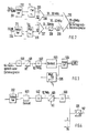
- Fig. 1 the left half shows the facilities available in the control center for a group of participants and the right half shows the facilities available at a participant in this group.
- the control center shown as a house, bears the reference symbol 100
- the facilities available to a subscriber which are shown as being in a single house, bear the reference symbol 111 as a whole.
- An optical waveguide 112 leads from the control center 100 to the one Group belonging participants is common to a star coupler SK, and from there participant-individual optical fibers L1 to L k each lead to a participant in the group.
- Both the subscriber-specific signals from the center to the group of subscribers, in the so-called downward direction, and the subscriber-specific signals from the group of subscribers to the center, in the so-called upward direction, are transmitted via this optical waveguide 112, with the Transmission in the downward direction a first wavelength ⁇ 0, eg equal to 1300 nm, and for transmission in the upward direction a second wavelength ⁇ 1, eg equal to 800 nm, is used.
- the optical waveguide 112 and the optical waveguide L1 to L k are thus used in wavelength division multiplexing for the transmission of signals in both directions. Details will be explained later.
- the system is used for the transmission of message signals of any kind, i.e. analog signals or digital signals, narrowband or broadband, of signals for distribution services, e.g. Television, or dialogue services, e.g. Telephony or data transmission, with subscriber-specific signals typically being transmitted in both directions.
- message signals of any kind, i.e. analog signals or digital signals, narrowband or broadband, of signals for distribution services, e.g. Television, or dialogue services, e.g. Telephony or data transmission, with subscriber-specific signals typically being transmitted in both directions.
- the system can advantageously be used for handling the dialog services such as telephony and data transmission separately from the distribution services for use cases in which there is either no need for distribution services or these are only to be introduced later using a separate system.
- the invention is explained using the example of the transmission of subscriber-specific signals in both transmission directions (dialog services).
- the subscriber-specific signals are also called telephone and data signals, which means the following: analog signals from a conventional telephone set, digital signals at 64 kbit / s from a digital telephone set, digital signals at 144 kbit / s from an ISDN terminal and digital data signals from 2 to 34 Mbit / s.
- the telephone and data signals to be transmitted to the group of subscribers come from a local exchange 118, from which they are input into an adaptation circuit with modulation / demodulation devices 119, which, as will be explained later, preferably processes a frequency division multiplex signal from them.
- This multiplex signal is converted into an optical signal in an electrical-optical converter 120 by intensity-modulating its output light of the wavelength ⁇ 0.
- the optical signal is coupled by means of a coupler 125 into the optical waveguide 112 and transmitted via this in the vicinity of the participants to the star coupler SK, distributed there to the optical waveguides L 1 to L k and transmitted via this to the participants.
- the optical fiber designated L3 is connected to the subscriber 111.
- the received optical signal is decoupled with a coupler 125, input into an optical-electrical converter 121 and converted into an electrical signal by the latter.
- the demodulator of a modem 123 takes the desired signal from the frequency division multiplex signal containing the telephone and data signals and converts it into the suitable and standardized form suitable for the respective terminal, telephone or data terminal or ISDN subscriber device. He ensures that only the telephone or data signals intended for the terminals of subscriber 111 can reach these terminals. In the simplest case, the subscriber has only a single terminal, for example a telephone set 127. If he has several terminals and therefore several signals must be taken from the frequency division multiplex signal, there are a corresponding number of modems.
- a participant with multiple devices is understood to mean both a single participant and a community of participants whose members have their living or business premises in an apartment building.
- the devices 121 and 123 are installed at a central location (e.g. basement) within the (single or multi-family) house and to connect the end devices to them via the existing house wiring.
- the modulator of the modem 123 modulates the telephone or data signals to be sent from a terminal of the subscriber to the central office on a carrier with a subscriber-specific frequency. If the subscriber (or community of subscribers) has multiple terminals, e.g. has several telephones, several modems modulate different carriers, and a multiplexer, not shown, combines these signals into a frequency band. Either a single modulated carrier or a frequency band consisting of a plurality of modulated carriers is then converted in an electrical-optical converter 122 into an optical signal which is present in the individual optical fibers, e.g. L3, is coupled by means of a coupler 126.
- the participants belonging to a group use an individual carrier frequency for each terminal belonging to a participant in the group. For example, there are 64 such carrier frequencies are provided. Instead of 64, another number, generally called m, of carrier frequencies can also be provided.
- the entirety of the subscribers grouped into a group of subscribers can thus operate up to m terminals for telephony or data transmission.
- the distribution among the individual participants is based on their individual communication needs and the available bandwidth in the system.
- the electrical-optical converters 122 present at the different participants all work with approximately the same operating wavelength ⁇ 1, so that in the star coupler SK e.g. 64 optical signals are irradiated with approximately the same operating wavelength ⁇ 1, which differ by the frequency (frequencies) of the carrier (carrier mixture) modulating the respective electrical-optical converter 127.
- an optical-to-electrical converter 129 which converts the received mixture of optical signals with the same wavelength, which the coupler 125 couples out of the optical waveguide 112, into a mixture of electrical signals with different carrier frequencies, and converts this to the input of the modulation / demodulation device 119.
- the telephone or data signals are present in the same form and quality that is prescribed for the transmission of telephone or ISDN signals or data signals.
- the couplers 125 and 126 are wavelength selective and separate the two wavelengths ⁇ 0 and ⁇ 1 without great optical losses and with very little crosstalk.
- FIG. 2 shows the modulator / multiplex part of the device 119 for telephone and data signals shown in FIG. 1, which is located in the control center.
- the telephone signals coming in from the local exchange (118 in FIG. 1) via a normal two-wire line 201 are converted in a so-called adapter 202 into a form which is suitable for transmission by a four-wire system with frequency modulation.
- the adapter 202 essentially has the function of a converter, for example for two-wire-four-wire implementation, for dialing signals, wake-up signals, etc.
- the signal resulting from this implementation reaches the modulation input of a modulator 203 and is modulated there onto a carrier with the frequency f 1 by means of frequency modulation .
- This carrier frequency f1 is individually a telephone subscriber line one of the participants in the assigned to the group of participants explained with reference to FIG. 1.
- the subscribers in this group can also use other connections, e.g. Connections to a digital network, e.g. to ISDN (Integrated Service Digital Network).
- a digital network e.g. to ISDN (Integrated Service Digital Network).
- the digital ISDN signals reach an adapter 211 for ISDN signals, and its output digital signal to the modulation input of a modulator 205 suitable for digital signals, in which it is e.g. by phase shift keying (English: phase shift keying, PSK) or frequency shift keying (eng .: frequency shift keying, FSK) a carrier with an individually assigned to this ISDN subscriber frequency f32 is modulated.
- phase shift keying English: phase shift keying, PSK
- frequency shift keying eng .: frequency shift keying, FSK
- the modulation of a carrier with the frequency f 1 by frequency modulation with telephone signals and in the second group the modulation of a carrier with the frequency f 3 by phase shift keying with ISDN signals is shown by the one group. Any mixes are possible.
- a first power adder 206 holds 32 modulated carriers with the different ones Carrier frequencies f1 to f32 to a frequency band with a bandwidth of 20 to 30 MHz
- a second power adder 207 also summarizes a group of 32 modulated carriers with the frequencies f1 to f32 to a frequency band with the same bandwidth 20 to 30 MHz.
- One of these two frequency bands is converted into the frequency band 30 to 40 MHz by means of a converter 208 and a downstream filter 209, and these two frequency bands are combined in a power adder 210 to form a frequency band of 20 to 40 MHz which contains up to 64 telephone and data signals may contain.
- This frequency band is the output signal of the device 119 shown in FIG. 1.
- a transmission of a large number of signals by frequency modulation of different carriers and by intensity modulation of a single optical transmitter by the signal mixture is known from "Electronics Letters", 22nd October 1987, VOL. 23, No. 22, pp. 1196 to 1197.
- the signals there are television signals and a transmission of telephone or ISDN signals (dialog services) is not mentioned.
- the frequency band from 20 to 40 MHz containing these signals is pre-filtered in a pre-filter 500, which is tuned to the frequency individually assigned to the subscriber connection under consideration, and the desired carrier is thereby separated from the mixture of modulated carriers, but this is done only incompletely, that is to say other carriers are still included in the output signal, though with lower amplitude.
- this signal is mixed with an auxiliary carrier HT, the frequency of which is selected such that the desired carrier is converted to an intermediate frequency of preferably 10.7 MHz which is uniform for all carriers.
- a downstream intermediate frequency filter 502 which is tuned to this intermediate frequency, practically isolates the useful information converted to this frequency from the other interfering carriers.
- An FM demodulator is used as the demodulator 503, if it is a telephone connection, and a PSK or FSK demodulator is used if it is an ISDN connection.
- the conversion to the intermediate frequency 10.7 MHz, subsequent filtering and FM demodulation corresponds to the signal processing in today's FM radio receivers and therefore has the advantage that cost-effective and proven circuits can be used. Another advantage is that uniform demodulators, uniform intermediate frequency filters and, apart from the frequency of the subcarrier, uniform intermediate frequency converters can be used for all subscriber connections.
- the telephone or ISDN signal appearing at the output of the demodulator 503 is finally implemented in an adapter 504, the function of which has already been explained in connection with FIG. 2, in such a way that it is suitable for the subscriber equipment (telephone set or ISDN device) standard-compliant signal is restored.
- the signals to be sent from this subscriber device to the control center are implemented by the adapter 504 and a modulator 505 connected downstream thereof, which is an FM modulator for an analog telephone signal and a phase shift keying or frequency shift keying modulator for a data signal, so that a modulated carrier is included one of the subscriber devices within a group of subscribers individually assigned frequency f 1 arises.
- this modulated carrier is then passed directly to the electrical-optical converter 122 of the subscriber shown in FIG. 1 or, if the subscriber has several terminals, via a multiplexer, not shown, so that in the latter case the converter 122 is known to be known existing light is modulated in its light intensity by a signal mixture of several modulated carriers.
- the modulators and demodulators shown in FIGS. 2 and 3 can be switchable so that they can either process telephone signals by frequency modulation or data signals by frequency or phase shift keying modulation.
- FIG. 4 shows the demodulator part of the device 119 from FIG. 1.
- an optical star coupler is shown as optical means for distributing the optical signal transmitted in the downward direction and for coupling the signals to be transmitted in the upward direction from the subscribers to the center into the optical waveguide 112.
- optical means can also be provided with distributed optical couplers, as is known per se from DE-A1-35 07 064, FIG. 1 mentioned at the beginning.
- optical means do not have to be passive, but can e.g. optical amplifiers or electrical amplifiers with associated optical-electrical and electrical-optical converters can be inserted.
- a supplement relates to the choice of frequencies for the transmission of the telephone or data signals, both in the downward and in the upward direction.
- the various signals explained above can be used as telephone or data signals.
- the carriers for the transmission of these signals e.g. lie in the frequency band from 20 MHz to 40 MHz.
- the carrier frequencies used for the transmission of the analog telephone signals and the digital signals with bit repetition frequencies from 64 to 144 kbit / s expediently have a uniform channel grid, i.e. a neighboring distance of the carrier frequencies, of 300 kHz. In this way, tried and tested circuits from VHF radio technology can be used to transmit the analog signals by means of frequency modulation.
- the carrier frequencies for the transmission of the digital data at 2 Mbit / s are expediently placed in the upper range of the frequency band from 20 MHz to 40 MHz, e.g. a carrier frequency for the transmission of such data at 38 MHz, the modulation for the transmission of the 2 Mbit / s digital signal requiring a bandwidth of approximately 1 to 2 MHz and thus a distance from adjacent carrier frequencies of 1 to 2 MHz.
- Another modification relates to the transmission of the frequency band containing a large number of modulated carriers as an optical signal.
- a single electrical-optical converter 120 receives, as an input signal, a frequency division multiplex signal which contains a multiplicity of modulated carriers.
- the problem with this type of transmission is the noise of the system, i.e. in the case of many carriers to be transmitted simultaneously via an optical transmitter, the signal-to-noise ratio in each of the individual channels can become insufficient.
- the fact that the mixture of signals from the many carriers allows only a very small degree of modulation per carrier of the laser used in the electrical-optical converter, so that the laser is not overdriven. If you increase the degree of modulation in the laser, the input signal comes to excessive peak values that overdrive the laser. Interferences between the useful signals then form interference products which can greatly reduce the quality of the useful signals.
- the total frequency band to be transmitted is divided into a plurality of subbands, each of which contains only part of the total of the modulated carriers to be transmitted, each subband in its own electrical-optical converter into an optical one Implement signal, using a uniform wavelength for all optical signals, and to couple these optical signals into the optical waveguide 112 (FIG. 1) running between the center and the group of subscribers.
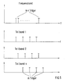
- a frequency band with a plurality of carriers is subdivided into n subbands such that a group of m carriers is contained in one of the subbands, and thus a total of the plurality m x n carriers of the originally present frequency band as shown in FIG. 5 on the different subbands is divided.
- the subbands can therefore each have the entire spectrum of the original transmission band. However, they contain a significantly smaller number of carriers than the original frequency band.
- each of the n subbands is given its own electrical-optical converter W1 to W n and that their output signals are combined by means of a star coupler SK1 to form an optical sum signal and in the optical waveguide 112 (leading to the group of participants) Fig. 1) are coupled.
- Each electrical-optical converter more precisely the laser it contains, can now be optimally controlled with regard to intermodulation distortion on the one hand and noise on the other. Because of the smaller number of carriers, the degree of modulation per carrier in the laser is significantly higher, so that the signal-to-noise ratio is significantly better for each carrier signal.
- the wavelength of the transducers W 1 to W n is preferably chosen as a uniform wavelength, for example approximately 1300 nm.
- the transmitted optical sum signal is converted into an electrical signal with a single optical receiver 121, as shown in FIG. 1, which contains all the original carriers, but with a far better signal quality than when transmitted with only one optical transmitter.
- the parallel use of a plurality of lasers described above has the further advantage of a higher light level at the output of the star coupler SK, which facilitates bridging a larger optical path loss or the distribution of the optical signals by means of optical star couplers to a number of subscribers.
- a supplement is described below that affects the safety of system users in the event of a fiber break. Because in the system preferably lasers are used as optical transmission elements, there is a need to switch off the lasers at the ends of the transmission path in the event of certain faults, for example when an excavator tears an optical fiber cable, in order to avoid the risk of eye accidents and the consequential damage associated therewith.
- optical transmission system it may be necessary to work with a high optical transmission power (more than -6 dBm) in order to achieve certain system properties, such as e.g. bridging a minimum distance between the control center and the participants or maintaining a certain signal-to-noise ratio.
- a return channel to send an alarm signal from the subscriber side to the transmitting center in order to switch off the laser there is not sufficient, since it is not possible to send back an alarm signal if the cable is defective, since each subscriber has only one cable or one single optical fiber is connected to the control center.
- one of the protective devices to be described below can therefore be present.
- FIG. 7 shows a protective device which provides an optical or electrical loop for monitoring an optical waveguide path. If a fiber break on an optical fiber link between two points A and B, for example, as shown in FIG. 7, is to be monitored between the control center 100 and the coupler SK, this is done with an optical or electrical loop 181, which runs in the immediate vicinity of the optical fiber line to be monitored. For example, a copper wire runs from a monitoring device 180 along the optical waveguide 112 to the coupler 113 and from there back to the monitoring device. The monitoring device sends a current via this loop, which flows continuously in the undisturbed operating state. If the cable is torn, the loop is also broken, so that the monitoring device causes the laser in the electrical-optical converter 120 to be switched off.
- an optical or electrical loop 181 which runs in the immediate vicinity of the optical fiber line to be monitored.
- a copper wire runs from a monitoring device 180 along the optical waveguide 112 to the coupler 113 and from there back to the monitoring device.
- the monitoring device sends a
- the copper wires can either be embedded in the accessory pack of the optical cable, or a thin copper cable can be laid parallel to the optical fiber cable.
- optical waveguides can also be used, which are part of the optical cable containing the transmission optical waveguide. In this case they are spliced together near the coupler and a fiber break is determined by the fact that the light path is interrupted via this optical loop from the center to the coupler and back.
- FIG. 8 shows a protective device in which an optical coupler 184 is spliced in between the electrical-optical converter 120 for the signal to be transmitted and the fiber cable, and the optical signal to be transmitted is coupled into the transmission optical fiber 112 via this coupler .
- the optical signals reflected and backscattered from this are detected at one end of the coupler 184 with an optical-electrical converter 182.
- a monitoring circuit 183 evaluating the electrical output signal of the converter 182 causes the laser contained in the electrical-optical converter 120 to be switched off when the detected light exceeds a predetermined threshold value. This is based on the fact that an excessively high level of the reflected light indicates a break in the optical waveguide.
- the protective device According to a development of the protective device according to FIG. 8, it is also possible to provide an optical-electrical converter at the still free end of the coupler 184. This then detects a portion of the light emitted by the electrical-optical converter and provides an electrical output signal that can be used on the one hand for electrical negative feedback of the laser in order to linearize the laser characteristic curve and whose low-frequency component can be used to set the operating point of the laser.
- the protective devices described above can not only be used in connection with the system according to the invention but can also be regarded as independent solutions when it comes to monitoring an optical transmission path between two points A and B with regard to a line interruption.
- the signals can also be transmitted in time division multiplex or in code division multiplex.
- the signals to be transmitted to a group of participants are converted into a digital time-division multiplex signal with a bit repetition frequency of e.g. about 8 Mbit / s combined, and this is transmitted, where appropriate it is also modulated onto a carrier and / or is limited to a suitable frequency band by coding with a line code.
- Analog telephone signals are converted into digital signals before time division multiplexing. Each participant has demultiplexing devices that extract the signals intended for him.
- the code division multiplex method is used to transmit the telephone and data signals from the center to the subscribers, the digital (or digitized) signals for a group are each multiplied by an address code and combined in a power adder to form a code division multiplex signal mixture, and this being transferred.
- Each participant has demultiplexing devices that take the signal intended for him.
- Time division multiplexing or code division multiplexing can also be used to transmit the telephone and data signals in the opposite direction.
- the multiplexers present at the subscribers then ensure that the telephone or data signals to be sent from a group of subscribers to the central station are converted into an optical signal with the wavelength ⁇ 1 in time segments of a (time-division multiplex) pulse frame or individually assigned address codes will.
- a mixture of optical signals is then transmitted to the control center, which are not determined by their wavelengths, but by the periods in which they contain their telephone or data signal, or by the codes of the respective electrical-optical converter 122 (FIG. 1 ) distinguish between the modulating digital signal (or the digital signals).
- the control center contains the suitable demultiplexing devices in order to resolve the electrical output signal of the optical-electrical converter 129 (FIG. 1) into its individual signals.
- the combination is preferably used that the transmission in the downward direction takes place in time division multiplexing and the transmission in the upward direction takes place in code division multiplexing.
Landscapes
- Engineering & Computer Science (AREA)
- Computer Networks & Wireless Communication (AREA)
- Signal Processing (AREA)
- Optical Communication System (AREA)
Applications Claiming Priority (2)
| Application Number | Priority Date | Filing Date | Title |
|---|---|---|---|
| DE3907497A DE3907497A1 (de) | 1989-03-08 | 1989-03-08 | Optisches nachrichtenuebertragungssystem fuer den teilnehmeranschlussbereich |
| DE3907497 | 1989-03-08 |
Publications (3)
| Publication Number | Publication Date |
|---|---|
| EP0386466A2 true EP0386466A2 (fr) | 1990-09-12 |
| EP0386466A3 EP0386466A3 (fr) | 1992-03-04 |
| EP0386466B1 EP0386466B1 (fr) | 1995-11-29 |
Family
ID=6375843
Family Applications (1)
| Application Number | Title | Priority Date | Filing Date |
|---|---|---|---|
| EP90102137A Expired - Lifetime EP0386466B1 (fr) | 1989-03-08 | 1990-02-03 | Système optique de transmission d'information dans la zone d'abonné |
Country Status (4)
| Country | Link |
|---|---|
| EP (1) | EP0386466B1 (fr) |
| AU (1) | AU623498B2 (fr) |
| DE (2) | DE3907497A1 (fr) |
| ES (1) | ES2082793T3 (fr) |
Cited By (5)
| Publication number | Priority date | Publication date | Assignee | Title |
|---|---|---|---|---|
| EP0477699A3 (en) * | 1990-09-14 | 1993-09-01 | Fujitsu Limited | Optical communication system |
| WO1995005041A1 (fr) * | 1993-08-04 | 1995-02-16 | British Telecommunications Public Limited Company | Systeme de telecommunications a fibres optiques |
| US5479286A (en) * | 1993-08-04 | 1995-12-26 | British Telecommunications Public Limited Company | Optical fibre communications system |
| EP0845842A1 (fr) * | 1996-12-02 | 1998-06-03 | Koninklijke KPN N.V. | Système optique avec une ou plusieurs sources de signal laser stabilisées |
| EP0709978A3 (fr) * | 1994-10-31 | 1998-08-12 | Alcatel SEL Aktiengesellschaft | Système optique de transmission pour des signaux de télévision par câble et pour des signaux d'abonnés individuels |
Families Citing this family (9)
| Publication number | Priority date | Publication date | Assignee | Title |
|---|---|---|---|---|
| DE3913300A1 (de) * | 1989-04-22 | 1990-10-25 | Standard Elektrik Lorenz Ag | Optisches nachrichtenuebertragungssystem fuer den teilnehmeranschlussbereich |
| IT1238032B (it) * | 1990-01-30 | 1993-06-23 | Pirelli Cavi Spa | Linea di telecomunicazione a fibre ottiche con canali separati di servizio |
| BE1004813A3 (nl) * | 1991-05-08 | 1993-02-02 | Bell Telephone Mfg | Optische zender/ontvangerinrichting. |
| DE4136801A1 (de) * | 1991-11-08 | 1993-05-13 | Daimler Benz Ag | Gruppenantenne |
| DE4214375C2 (de) * | 1992-04-30 | 1996-12-05 | Siemens Ag | Optisches Teilnehmeranschlußnetz mit Wellenlängenmultiplex und mehrdeutigem optischen Multiplexer/Demultiplexer |
| DE19505578A1 (de) * | 1995-02-18 | 1996-08-22 | Sel Alcatel Ag | Optisches Übertragungssystem für Kabelfernsehsignale und Video- und Telekommunikationssignale |
| DE19635990A1 (de) * | 1996-09-05 | 1998-03-12 | Sel Alcatel Ag | Sendeeinrichtung und Verfahren zur optischen Übertragung von elektrischen Frequenzmultiplexsignalen |
| DE19701888A1 (de) * | 1997-01-21 | 1998-07-23 | Alsthom Cge Alcatel | System zur optischen Übertragung von Informationen |
| DE19722370A1 (de) | 1997-05-28 | 1998-12-03 | Alsthom Cge Alcatel | Empfänger für ein optisches Nachrichtenübertragungssystem und Verfahren zu dessen Betrieb |
Family Cites Families (7)
| Publication number | Priority date | Publication date | Assignee | Title |
|---|---|---|---|---|
| DE3010802A1 (de) * | 1980-03-20 | 1981-09-24 | Siemens AG, 1000 Berlin und 8000 München | Schaltungsanordnung zur multiplexuebertragung mehrerer nachrichtenbaender |
| DE3106682A1 (de) * | 1981-02-23 | 1982-09-09 | Siemens AG, 1000 Berlin und 8000 München | Nachrichtenuebertragungssystem fuer duplex-betrieb ueber eine lichtleitfaser |
| US4592043A (en) * | 1983-07-08 | 1986-05-27 | At&T Bell Laboratories | Wavelength division multiplexing optical communications systems |
| DE3507064A1 (de) * | 1985-02-28 | 1986-08-28 | Standard Elektrik Lorenz Ag, 7000 Stuttgart | Optisches nachrichtenuebertragungssystem im teilnehmeranschlussbereich |
| AU602553B2 (en) * | 1987-01-05 | 1990-10-18 | British Telecommunications Public Limited Company | Optical communications network |
| CA1315340C (fr) * | 1987-05-06 | 1993-03-30 | David Wynford Faulkner | Commande de systemes optiques |
| US4933929A (en) * | 1987-06-29 | 1990-06-12 | Nec Corporation | Wavelength multiplexed optical transmitter for generating constant-amplitude angle-modulated beams to eliminate phase noise in adjacent transmission channels |
-
1989
- 1989-03-08 DE DE3907497A patent/DE3907497A1/de not_active Withdrawn
-
1990
- 1990-02-03 ES ES90102137T patent/ES2082793T3/es not_active Expired - Lifetime
- 1990-02-03 EP EP90102137A patent/EP0386466B1/fr not_active Expired - Lifetime
- 1990-02-03 DE DE59009907T patent/DE59009907D1/de not_active Expired - Fee Related
- 1990-02-28 AU AU50180/90A patent/AU623498B2/en not_active Ceased
Cited By (10)
| Publication number | Priority date | Publication date | Assignee | Title |
|---|---|---|---|---|
| EP0477699A3 (en) * | 1990-09-14 | 1993-09-01 | Fujitsu Limited | Optical communication system |
| US5896211A (en) * | 1990-09-14 | 1999-04-20 | Fujitsu Limited | Optical communication system |
| WO1995005041A1 (fr) * | 1993-08-04 | 1995-02-16 | British Telecommunications Public Limited Company | Systeme de telecommunications a fibres optiques |
| US5479286A (en) * | 1993-08-04 | 1995-12-26 | British Telecommunications Public Limited Company | Optical fibre communications system |
| AU692455B2 (en) * | 1993-08-04 | 1998-06-11 | British Telecommunications Public Limited Company | Optical fibre communications system |
| EP0709978A3 (fr) * | 1994-10-31 | 1998-08-12 | Alcatel SEL Aktiengesellschaft | Système optique de transmission pour des signaux de télévision par câble et pour des signaux d'abonnés individuels |
| EP0845842A1 (fr) * | 1996-12-02 | 1998-06-03 | Koninklijke KPN N.V. | Système optique avec une ou plusieurs sources de signal laser stabilisées |
| NL1004667C2 (nl) * | 1996-12-02 | 1998-06-03 | Nederland Ptt | Optische systemen met een of meer gestabiliseerde lasersignaalbronnen. |
| WO1998025328A1 (fr) * | 1996-12-02 | 1998-06-11 | Koninklijke Kpn N.V. | Systemes optiques avec une ou plusieurs sources de signaux laser stabilises |
| US6097523A (en) * | 1996-12-02 | 2000-08-01 | Koninklijke Kpn N.V. | Optical systems with one or more stabilized laser signal sources |
Also Published As
| Publication number | Publication date |
|---|---|
| ES2082793T3 (es) | 1996-04-01 |
| AU5018090A (en) | 1990-09-13 |
| DE59009907D1 (de) | 1996-01-11 |
| EP0386466A3 (fr) | 1992-03-04 |
| DE3907497A1 (de) | 1990-09-13 |
| AU623498B2 (en) | 1992-05-14 |
| EP0386466B1 (fr) | 1995-11-29 |
Similar Documents
| Publication | Publication Date | Title |
|---|---|---|
| EP0499065B1 (fr) | Système de transmission optique pour zone d'abonnés utilisant des amplificateurs optiques | |
| DE69125314T2 (de) | Optisches Übertragungssystem und -verfahren | |
| EP0709978B1 (fr) | Système optique de transmission pour des signaux de télévision par câble et pour des signaux d'abonnés individuels | |
| EP0727889B1 (fr) | Système de transmission optique pour signaux de télévision par câble et pour signaux de vidéo et télécommunication | |
| EP0386482B1 (fr) | Système de transmission optique pour connexion d'abonné | |
| DE69127568T2 (de) | Telemetrie für optischen Faserzwischenverstärker | |
| DE69032454T2 (de) | Verfahren und anordnung zum uebertragen von breitbandigen, amplitudenmodulierten radiofrequenzsignalen ueber optische verbindungen | |
| DE69123674T2 (de) | Mobiles Kommunikationssystem | |
| EP0193190B1 (fr) | Système optique de transmission d'information dans la zone d'abonnement | |
| EP0386466B1 (fr) | Système optique de transmission d'information dans la zone d'abonné | |
| DE19654173A1 (de) | Vorrichtung und Verfahren zur schnellen Datenübertragung über eine Abzweigleitung eines Nachrichtenübertragungssystems auf Hochspannungsleitungen | |
| EP0227164A2 (fr) | Système de transmission à intégration de services d'informations numériques avec des dispositifs pour la transmission simultanée de signaux à large bande et à bande étroite | |
| EP0053236A1 (fr) | Système de transmission numérique à service intégré | |
| EP0380945A2 (fr) | Système optique de transmission de communications à large bande, en particulier dans la région de branchement d'abonnés | |
| EP0817410A2 (fr) | Terminal pour réseau optique, réseau optique et commutateur pour ce réseau | |
| DE3786723T2 (de) | Vermittlungstechniken für Frequenzmultiplex-Kommunikationssysteme. | |
| DE69017200T2 (de) | Optisches zweiwegübertragungssystem. | |
| DE19643872A1 (de) | Optische Netzabschlußeinheit eines hybriden Glasfaser-Koaxialkabel-Zugangsnetzes | |
| DE4226838B4 (de) | Optisches, breitbandiges Nachrichtenübertragungssystem für Kommunikations- und Verteildienste | |
| EP0084371B1 (fr) | Système à fréquences porteuses pour fonctionnement à quatre fils | |
| DE69431786T2 (de) | Übertragungsnetz mit Vielfachzugriff und Unterträger | |
| DE69024119T2 (de) | Polarisationsregelung von bidirektional übertragenen Strahlenbündeln durch eine einzige Polarisationssteuerung | |
| DE69216435T2 (de) | Verfahren und Netzwerk zur Übertragung von Nachrichten über Frequenzkanäle | |
| DE69215559T2 (de) | System zur Hilfssignalübertragung mittels einer optischen Verbindung | |
| DE19701888A1 (de) | System zur optischen Übertragung von Informationen |
Legal Events
| Date | Code | Title | Description |
|---|---|---|---|
| PUAI | Public reference made under article 153(3) epc to a published international application that has entered the european phase |
Free format text: ORIGINAL CODE: 0009012 |
|
| AK | Designated contracting states |
Kind code of ref document: A2 Designated state(s): AT BE CH DE DK ES FR GB IT LI NL SE |
|
| PUAL | Search report despatched |
Free format text: ORIGINAL CODE: 0009013 |
|
| AK | Designated contracting states |
Kind code of ref document: A3 Designated state(s): AT BE CH DE DK ES FR GB IT LI NL SE |
|
| 17P | Request for examination filed |
Effective date: 19920411 |
|
| RAP3 | Party data changed (applicant data changed or rights of an application transferred) |
Owner name: ALCATEL SEL AKTIENGESELLSCHAFT |
|
| 17Q | First examination report despatched |
Effective date: 19940407 |
|
| GRAA | (expected) grant |
Free format text: ORIGINAL CODE: 0009210 |
|
| AK | Designated contracting states |
Kind code of ref document: B1 Designated state(s): CH DE ES FR GB IT LI SE |
|
| REF | Corresponds to: |
Ref document number: 59009907 Country of ref document: DE Date of ref document: 19960111 |
|
| ITF | It: translation for a ep patent filed | ||
| ET | Fr: translation filed | ||
| GBT | Gb: translation of ep patent filed (gb section 77(6)(a)/1977) |
Effective date: 19960215 |
|
| REG | Reference to a national code |
Ref country code: ES Ref legal event code: FG2A Ref document number: 2082793 Country of ref document: ES Kind code of ref document: T3 |
|
| PLBE | No opposition filed within time limit |
Free format text: ORIGINAL CODE: 0009261 |
|
| STAA | Information on the status of an ep patent application or granted ep patent |
Free format text: STATUS: NO OPPOSITION FILED WITHIN TIME LIMIT |
|
| 26N | No opposition filed | ||
| PGFP | Annual fee paid to national office [announced via postgrant information from national office to epo] |
Ref country code: GB Payment date: 20010112 Year of fee payment: 12 |
|
| PGFP | Annual fee paid to national office [announced via postgrant information from national office to epo] |
Ref country code: CH Payment date: 20010115 Year of fee payment: 12 |
|
| PGFP | Annual fee paid to national office [announced via postgrant information from national office to epo] |
Ref country code: SE Payment date: 20010205 Year of fee payment: 12 Ref country code: FR Payment date: 20010205 Year of fee payment: 12 Ref country code: DE Payment date: 20010205 Year of fee payment: 12 |
|
| PGFP | Annual fee paid to national office [announced via postgrant information from national office to epo] |
Ref country code: ES Payment date: 20010220 Year of fee payment: 12 |
|
| REG | Reference to a national code |
Ref country code: GB Ref legal event code: IF02 |
|
| PG25 | Lapsed in a contracting state [announced via postgrant information from national office to epo] |
Ref country code: GB Free format text: LAPSE BECAUSE OF NON-PAYMENT OF DUE FEES Effective date: 20020203 |
|
| PG25 | Lapsed in a contracting state [announced via postgrant information from national office to epo] |
Ref country code: SE Free format text: LAPSE BECAUSE OF NON-PAYMENT OF DUE FEES Effective date: 20020204 Ref country code: ES Free format text: LAPSE BECAUSE OF NON-PAYMENT OF DUE FEES Effective date: 20020204 |
|
| PG25 | Lapsed in a contracting state [announced via postgrant information from national office to epo] |
Ref country code: LI Free format text: LAPSE BECAUSE OF NON-PAYMENT OF DUE FEES Effective date: 20020228 Ref country code: CH Free format text: LAPSE BECAUSE OF NON-PAYMENT OF DUE FEES Effective date: 20020228 |
|
| PG25 | Lapsed in a contracting state [announced via postgrant information from national office to epo] |
Ref country code: DE Free format text: LAPSE BECAUSE OF NON-PAYMENT OF DUE FEES Effective date: 20020903 |
|
| EUG | Se: european patent has lapsed |
Ref document number: 90102137.8 |
|
| GBPC | Gb: european patent ceased through non-payment of renewal fee |
Effective date: 20020203 |
|
| REG | Reference to a national code |
Ref country code: CH Ref legal event code: PL |
|
| PG25 | Lapsed in a contracting state [announced via postgrant information from national office to epo] |
Ref country code: FR Free format text: LAPSE BECAUSE OF NON-PAYMENT OF DUE FEES Effective date: 20021031 |
|
| REG | Reference to a national code |
Ref country code: FR Ref legal event code: ST |
|
| PG25 | Lapsed in a contracting state [announced via postgrant information from national office to epo] |
Ref country code: IT Free format text: LAPSE BECAUSE OF NON-PAYMENT OF DUE FEES;WARNING: LAPSES OF ITALIAN PATENTS WITH EFFECTIVE DATE BEFORE 2007 MAY HAVE OCCURRED AT ANY TIME BEFORE 2007. THE CORRECT EFFECTIVE DATE MAY BE DIFFERENT FROM THE ONE RECORDED. Effective date: 20050203 |