EP0386479A2 - Générateur d'ondes de choc - Google Patents
Générateur d'ondes de choc Download PDFInfo
- Publication number
- EP0386479A2 EP0386479A2 EP90102352A EP90102352A EP0386479A2 EP 0386479 A2 EP0386479 A2 EP 0386479A2 EP 90102352 A EP90102352 A EP 90102352A EP 90102352 A EP90102352 A EP 90102352A EP 0386479 A2 EP0386479 A2 EP 0386479A2
- Authority
- EP
- European Patent Office
- Prior art keywords
- wave generator
- source
- reflector
- shock wave
- flat
- Prior art date
- Legal status (The legal status is an assumption and is not a legal conclusion. Google has not performed a legal analysis and makes no representation as to the accuracy of the status listed.)
- Granted
Links
- 230000035939 shock Effects 0.000 title claims abstract description 31
- 239000010949 copper Substances 0.000 claims description 19
- RYGMFSIKBFXOCR-UHFFFAOYSA-N Copper Chemical compound [Cu] RYGMFSIKBFXOCR-UHFFFAOYSA-N 0.000 claims description 16
- 229910052802 copper Inorganic materials 0.000 claims description 15
- 239000012528 membrane Substances 0.000 claims description 13
- 238000009413 insulation Methods 0.000 claims description 10
- 229910001220 stainless steel Inorganic materials 0.000 claims description 4
- 239000010935 stainless steel Substances 0.000 claims description 4
- 239000004020 conductor Substances 0.000 claims description 2
- 239000002184 metal Substances 0.000 claims description 2
- 229910052751 metal Inorganic materials 0.000 claims description 2
- 239000010410 layer Substances 0.000 description 11
- 229920003223 poly(pyromellitimide-1,4-diphenyl ether) Polymers 0.000 description 7
- 239000011888 foil Substances 0.000 description 5
- 230000000694 effects Effects 0.000 description 3
- 238000004804 winding Methods 0.000 description 3
- 230000008878 coupling Effects 0.000 description 2
- 238000010168 coupling process Methods 0.000 description 2
- 238000005859 coupling reaction Methods 0.000 description 2
- 238000002604 ultrasonography Methods 0.000 description 2
- 230000015572 biosynthetic process Effects 0.000 description 1
- 239000000919 ceramic Substances 0.000 description 1
- 238000010276 construction Methods 0.000 description 1
- 238000001816 cooling Methods 0.000 description 1
- 238000010438 heat treatment Methods 0.000 description 1
- 238000003384 imaging method Methods 0.000 description 1
- 238000001727 in vivo Methods 0.000 description 1
- 239000012212 insulator Substances 0.000 description 1
- 230000010354 integration Effects 0.000 description 1
- 239000007788 liquid Substances 0.000 description 1
- 230000004807 localization Effects 0.000 description 1
- 238000000034 method Methods 0.000 description 1
- 230000035515 penetration Effects 0.000 description 1
- 230000005855 radiation Effects 0.000 description 1
- 239000002356 single layer Substances 0.000 description 1
Images

Classifications
-
- G—PHYSICS
- G10—MUSICAL INSTRUMENTS; ACOUSTICS
- G10K—SOUND-PRODUCING DEVICES; METHODS OR DEVICES FOR PROTECTING AGAINST, OR FOR DAMPING, NOISE OR OTHER ACOUSTIC WAVES IN GENERAL; ACOUSTICS NOT OTHERWISE PROVIDED FOR
- G10K15/00—Acoustics not otherwise provided for
- G10K15/04—Sound-producing devices
- G10K15/043—Sound-producing devices producing shock waves
-
- G—PHYSICS
- G10—MUSICAL INSTRUMENTS; ACOUSTICS
- G10K—SOUND-PRODUCING DEVICES; METHODS OR DEVICES FOR PROTECTING AGAINST, OR FOR DAMPING, NOISE OR OTHER ACOUSTIC WAVES IN GENERAL; ACOUSTICS NOT OTHERWISE PROVIDED FOR
- G10K11/00—Methods or devices for transmitting, conducting or directing sound in general; Methods or devices for protecting against, or for damping, noise or other acoustic waves in general
- G10K11/18—Methods or devices for transmitting, conducting or directing sound
- G10K11/26—Sound-focusing or directing, e.g. scanning
- G10K11/28—Sound-focusing or directing, e.g. scanning using reflection, e.g. parabolic reflectors
-
- G—PHYSICS
- G10—MUSICAL INSTRUMENTS; ACOUSTICS
- G10K—SOUND-PRODUCING DEVICES; METHODS OR DEVICES FOR PROTECTING AGAINST, OR FOR DAMPING, NOISE OR OTHER ACOUSTIC WAVES IN GENERAL; ACOUSTICS NOT OTHERWISE PROVIDED FOR
- G10K9/00—Devices in which sound is produced by vibrating a diaphragm or analogous element, e.g. fog horns, vehicle hooters or buzzers
- G10K9/12—Devices in which sound is produced by vibrating a diaphragm or analogous element, e.g. fog horns, vehicle hooters or buzzers electrically operated
Definitions
- the invention relates to a shock wave source according to the preamble of claim 1.
- a punctiform shock wave source for lithotripters is known from DE-PS 23 51 247.
- a flat shock wave source is known from DE-OS 31 19 295. It is made up of individual piezoceramic elements. This area source is either self-focusing as a spherical cap or it is provided with an imaging system such as reflectors or lenses for the necessary focusing. The formation of a shock front from a sound pressure pulse at the area source is given by nonlinear propagation with sufficient intensity.
- a shock wave source for non-contact lithotripsy which has a flat wave generator (an electromagnetic shock wave tube) and a parabolic reflector. This focuses the flat shock wave on the concretion in the patient's body.
- This shock wave source forms the preamble of claim 1.
- the following essential technical requirements can be derived from a shock wave system: - high dynamic performance - Good focusing of the most unipolar pulses possible - little pressure and especially tension when entering the patient - Good and accurate location options using ultrasound and / or X-ray - compact construction - long life span.
- the source is arranged in a ring in the plane of incidence of the paraboloid, so that a kind of "perforated cylinder" results because of the finite thickness.
- the hole in the middle is necessary because the focus is on the source side.
- the axial opening i.e. the ring-shaped design of the source, makes sense, since at a certain minimum aperture angle, the reflected sound is reflected from the upper paraboloid edge onto the source and would therefore be lost for focusing.
- the reflected, spherically convergent wavefront is therefore focused on a high aperture with a free central area, which is then available, for example, for location systems.
- the possibilities of the arrangement are very variable - so the effective depth of focus can be reduced if the ring of the source has such a large inner radius that it can be put around the patient. The focus is then between the source and the reflector.
- the limiting factor for the inner radius here is not the shading of the source itself, but the space for the patient or the part of the patient to be treated in the space between the reflector and the source.
- the focus is behind the Shock wave source.
- the shock waves run through the hole in the middle towards this point.
- Advantages of this source / reflector geometry can be mentioned: - High variability and flexibility regarding the size of the source, so that the flat surface source can be designed according to performance requirements and performance options. - The arrangement can be used equally for piezoelectric as well as for electromagnetic sound pulse generation. - The flat shape of the source simplifies high-performance design (insulation, contacting). - Good focusing due to high aperture and sound field freedom in the middle. - The central freedom from the sound field leaves enough space for positioning systems (ultrasound and / or X-ray). - Location and shock wave do not interfere. - Reduction of the axial pressure and, in particular, tensile components due to central freedom from sound fields.
- a cylindrical source which emits with its outer surface onto the reflector surrounding it.
- This reflector is generated by rotating a partial parabola around a line that is perpendicular to the focal point of the Parabola runs and at the same time represents the axis of symmetry of the cylindrical source.
- a cylinder shaft is generated by the cylinder jacket which radiates sound radially outwards.
- This arrangement can be realized, for example, by a compact tube made of piezoceramic, on the lateral surface of which the piezoceramic elements are arranged. This geometry allows a high variability in terms of focus length and aperture, similar to the design of the ellipsoid reflector for underwater spark discharge, especially if the source has a high power density.
- an electromagnetic source in cylinder geometry i.e. a longitudinal coil with a conductive cylinder jacket as a radiating membrane.
- the sound source then consists of a coil, insulation and a conductive outer cylinder which is deflected radially outward when the coil is subjected to current or pulses due to the repulsive force effect between the primary and secondary-induced current.
- the technical problems such as tightness and precise coupling between the coil, membrane and insulation, as well as the expansion in the circumferential direction with radial expansion (radiation) are manageable. In addition to the necessary total area, these determine the minimum radius.
- a single-layer cylindrical coil (flat coil) is used, which can be wound from flat conductor tracks that are applied to an insulator carrier.
- the cylindrical membrane can, for example, be composed of a copper layer and a stainless steel layer.
- the copper layer ensures good electrical properties
- the stainless steel jacket provides good mechanical strength.
- cylindrical membrane from a plurality of metal layers which are separated from one another by insulating foils, as has already been proposed in German patent application P 37 43 822. This can reduce eddy current losses.
- One possible implementation is e.g. in the use of e.g. 10 mm wide copper ribbon with a thickness of e.g. 0.2 mm, matched to the penetration depth of the field for a given pulse duration and the necessary mechanical stability of the cylinder jacket membrane.
- the thickness of the insulation determines the high voltage strength.
- An exemplary usable copper flat tape insulated with Kapton should be at least three times as wide as the copper track for the insulation strength of the coil in the longitudinal direction (winding direction).
- the membrane can then be shrunk onto the coil without any gaps. This can e.g. by heating, sliding open and then cooling.
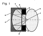
- FIG. 1 shows a patient's body K and a shock wave source, consisting of the wave generator W and the reflector R.
- the wave generator W is designed here as a cylinder, on the top surface D of which faces the reflector R, the radiating elements E (for example piezo elements or an electromagnetic coil) are arranged are.
- the elements E radiate the waves to the left towards the reflector R, from where they are focused on the focal point F, which lies on the central axis A of the reflector.
- the reflector R is filled with a liquid and sealed off from the body K with a membrane. Possible coupling pads are not shown here.
- the wave normals of shock waves, which are generated by the elements E, run to the left onto the reflector, are reflected from there, and meet at the focal point F are drawn in.
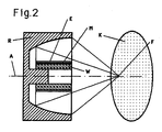
- FIG. 2 shows another embodiment in which the shock wave source has a cylindrical wave generator W, in which the radiating elements E are applied to the outer surface M of the wave generator.
- the elements E radiate radially outwards.
- the shock waves are in turn focused by the reflector R on the focal point F, which lies on the one hand in the patient's body K and on the other hand on the axis of symmetry A of the shock wave source.
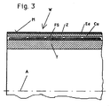
- FIG. 3 shows an embodiment of a wave generator as can be used in the shock wave source of FIG. 2.
- the wave generator W here consists of a ceramic or glass-like carrier T, around which a flat coil FS is wound.
- This coil can be constructed from discrete copper wire, it can also be made by copper-coated Kapton, which is appropriately etched so that a single copper strip remains, which was then wound up.
- This carrier T with flat coil FS is surrounded by a cylindrical membrane Z which surrounds the carrier T like a jacket M.
- the cylinder diaphragm Z in this version consists of a copper layer Cu and a stainless steel layer Ed.
- the insulation (not shown) between the tape reel FS and the copper membrane Z can consist of a separate layer of Kapton; it can be taken over by the copper-coated, etched-off Kapton foil itself with a suitable winding technique, as described with reference to FIG. 5.
- the gap visible in the figure between the insulation of the coil FS and the membrane Z should be designed as narrow as possible, ideally zero.
- FIG. 4 schematically shows a shock wave source with the radially radiating cylindrical wave generator W and the reflector R which surrounds it. Realizable size relationships of the components to one another and angles can be read from this figure.
- Figure 4 shows a scale (1: 2) implementation. The data in detail: - Coil length: 13 cm - Coil diameter: 6 cm - Focus length: 15 cm - aperture 42.40 - Paraboloid diameter: 27.4 cm
- the radiating surface corresponds to that of a flat one EMSE with a diameter of almost 18 cm.
- the finite radius of the cylinder source results in a minimal aperture angle, which, however, does not come about due to shading of the source. Extending the cylinder allows the surface to be enlarged, with the parabolic diameter increasing to the same extent.
- FIG. 5 shows schematically examples of two Kapton foils Ka, each carrying a strip of copper Cu.
- the copper strip is applied in the middle on the left Kapton foil, on the right on the right.
- the left Kapton layers then overlap over the previously wound copper layers Cu and serve as insulation there.
- two insulation layers then overlap.
Landscapes
- Physics & Mathematics (AREA)
- Engineering & Computer Science (AREA)
- Acoustics & Sound (AREA)
- Multimedia (AREA)
- Surgical Instruments (AREA)
- Apparatuses For Generation Of Mechanical Vibrations (AREA)
- Surface Acoustic Wave Elements And Circuit Networks Thereof (AREA)
- Magnetic Resonance Imaging Apparatus (AREA)
- Waveguides (AREA)
- Waveguide Aerials (AREA)
Applications Claiming Priority (2)
| Application Number | Priority Date | Filing Date | Title |
|---|---|---|---|
| DE3907605 | 1989-03-09 | ||
| DE3907605A DE3907605C2 (de) | 1989-03-09 | 1989-03-09 | Stosswellenquelle |
Publications (3)
| Publication Number | Publication Date |
|---|---|
| EP0386479A2 true EP0386479A2 (fr) | 1990-09-12 |
| EP0386479A3 EP0386479A3 (fr) | 1991-05-29 |
| EP0386479B1 EP0386479B1 (fr) | 1996-10-23 |
Family
ID=6375909
Family Applications (1)
| Application Number | Title | Priority Date | Filing Date |
|---|---|---|---|
| EP90102352A Expired - Lifetime EP0386479B1 (fr) | 1989-03-09 | 1990-02-07 | Générateur d'ondes de choc |
Country Status (5)
| Country | Link |
|---|---|
| US (1) | US5174280A (fr) |
| EP (1) | EP0386479B1 (fr) |
| JP (1) | JPH0832265B2 (fr) |
| DE (1) | DE3907605C2 (fr) |
| ES (1) | ES2096564T3 (fr) |
Cited By (1)
| Publication number | Priority date | Publication date | Assignee | Title |
|---|---|---|---|---|
| US11065645B2 (en) | 2015-04-24 | 2021-07-20 | Les Solutions Medicales Soundbite Inc. | Method and system for generating mechanical pulses |
Families Citing this family (49)
| Publication number | Priority date | Publication date | Assignee | Title |
|---|---|---|---|---|
| DE3835318C1 (fr) * | 1988-10-17 | 1990-06-28 | Storz Medical Ag, Kreuzlingen, Ch | |
| DE4110102A1 (de) * | 1991-03-27 | 1992-10-01 | Siemens Ag | Elektromagnetische druckimpulsquelle |
| US7189209B1 (en) | 1996-03-29 | 2007-03-13 | Sanuwave, Inc. | Method for using acoustic shock waves in the treatment of a diabetic foot ulcer or a pressure sore |
| US6390995B1 (en) | 1997-02-12 | 2002-05-21 | Healthtronics Surgical Services, Inc. | Method for using acoustic shock waves in the treatment of medical conditions |
| US6869407B2 (en) * | 2001-09-12 | 2005-03-22 | Moshe Ein-Gal | Acoustic wave device |
| US7048699B2 (en) * | 2001-09-12 | 2006-05-23 | Moshe Ein-Gal | Non-cylindrical acoustic wave device |
| US7311677B1 (en) * | 2002-06-26 | 2007-12-25 | Fields John G | Energy concentrator system and method |
| US8257282B2 (en) | 2004-02-19 | 2012-09-04 | General Patent, Llc | Pressure pulse/shock wave apparatus for generating waves having plane, nearly plane, convergent off target or divergent characteristics |
| US20060100549A1 (en) * | 2004-10-22 | 2006-05-11 | Reiner Schultheiss | Pressure pulse/shock wave apparatus for generating waves having nearly plane or divergent characteristics |
| US7559904B2 (en) * | 2003-07-17 | 2009-07-14 | Moshe Ein-Gal | Shockwave generating system |
| US7338513B2 (en) * | 2003-10-30 | 2008-03-04 | Cambridge Endoscopic Devices, Inc. | Surgical instrument |
| US20050165275A1 (en) * | 2004-01-22 | 2005-07-28 | Kenneth Von Felten | Inspection device insertion tube |
| US7507213B2 (en) * | 2004-03-16 | 2009-03-24 | General Patent Llc | Pressure pulse/shock wave therapy methods for organs |
| US7497835B2 (en) * | 2004-10-22 | 2009-03-03 | General Patent Llc | Method of treatment for and prevention of periodontal disease |
| US7544171B2 (en) * | 2004-10-22 | 2009-06-09 | General Patent Llc | Methods for promoting nerve regeneration and neuronal growth and elongation |
| US7601127B2 (en) * | 2004-10-22 | 2009-10-13 | General Patent, Llc | Therapeutic stimulation of genital tissue or reproductive organ of an infertility or impotence diagnosed patient |
| US7497836B2 (en) * | 2004-10-22 | 2009-03-03 | General Patent Llc | Germicidal method for treating or preventing sinusitis |
| US7578796B2 (en) * | 2004-10-22 | 2009-08-25 | General Patent Llc | Method of shockwave treating fish and shellfish |
| US7537572B2 (en) * | 2004-10-22 | 2009-05-26 | General Patent, Llc | Treatment or pre-treatment for radiation/chemical exposure |
| US7600343B2 (en) * | 2004-10-22 | 2009-10-13 | General Patent, Llc | Method of stimulating plant growth |
| US7497834B2 (en) * | 2004-10-22 | 2009-03-03 | General Patent Llc | Germicidal method for eradicating or preventing the formation of biofilms |
| US7988648B2 (en) * | 2005-03-04 | 2011-08-02 | General Patent, Llc | Pancreas regeneration treatment for diabetics using extracorporeal acoustic shock waves |
| DE102005017724A1 (de) * | 2005-04-15 | 2006-11-09 | Ast Gmbh | Fokussiereinrichtung für eine Vorrichtung zur Erzeugung von Stoßwellen |
| US8277397B2 (en) * | 2005-06-15 | 2012-10-02 | Moshe Ein-Gal | Wave generating device with inner reflector |
| US20070239074A1 (en) * | 2006-02-15 | 2007-10-11 | Moshe Ein-Gal | Line focusing acoustic wave source |
| US7610079B2 (en) * | 2006-07-25 | 2009-10-27 | Ast Gmbh | Shock wave imaging system |
| DE102006050781A1 (de) * | 2006-10-27 | 2008-04-30 | Ast Gmbh | Vorrichtung zur räumlichen Positionierung eines Gerätes |
| KR100840771B1 (ko) * | 2006-11-02 | 2008-06-23 | 조성찬 | 압전 세라믹 소자를 이용한 충격파 생성 장치 |
| US8529451B2 (en) * | 2007-10-01 | 2013-09-10 | General Patent, Llc | Shock wave coupling adapter and method of use |
| US20100036294A1 (en) | 2008-05-07 | 2010-02-11 | Robert Mantell | Radially-Firing Electrohydraulic Lithotripsy Probe |
| US9913748B2 (en) | 2009-10-30 | 2018-03-13 | Avner Spector | Method and apparatus for treatment of erectile dysfunction with extracorporeal shockwaves |
| WO2012108854A2 (fr) * | 2009-12-22 | 2012-08-16 | Phoenix Science & Technology, Inc. | Source de réseau d'étinceleur |
| US7918309B1 (en) * | 2010-07-07 | 2011-04-05 | Robert Kenneth Vierra | Apparatus for producing a continuous sonic boom |
| US9833373B2 (en) | 2010-08-27 | 2017-12-05 | Les Solutions Médicales Soundbite Inc. | Mechanical wave generator and method thereof |
| DE102011011541A1 (de) * | 2011-02-17 | 2012-08-23 | Fraunhofer-Gesellschaft zur Förderung der angewandten Forschung e.V. | Ultraschallwandleranordnung mit einem Ultraschallwellen fokussierenden Mittel sowie Verfahren zum fokussierten Abstrahlen sowie Empfangen von fokussierten Ultraschallwellen |
| FR2973685B1 (fr) * | 2011-04-05 | 2014-11-28 | Eye Tech Care | Dispositif de therapie oculaire par ultrasons a reflecteur |
| ES2703539T3 (es) | 2013-03-11 | 2019-03-11 | Northgate Tech Inc | Litotriptor electrohidráulico no focalizado |
| FR3007926B1 (fr) * | 2013-06-27 | 2016-01-08 | Areva Np | Transducteur a ultrasons |
| US11458069B2 (en) | 2016-04-18 | 2022-10-04 | Softwave Tissue Regeneration Technologies, Llc | Acoustic shock wave therapeutic methods to treat medical conditions using reflexology zones |
| US11389373B2 (en) | 2016-04-18 | 2022-07-19 | Softwave Tissue Regeneration Technologies, Llc | Acoustic shock wave therapeutic methods to prevent or treat opioid addiction |
| US11389370B2 (en) | 2016-04-18 | 2022-07-19 | Softwave Tissue Regeneration Technologies, Llc | Treatments for blood sugar levels and muscle tissue optimization using extracorporeal acoustic shock waves |
| US11389371B2 (en) | 2018-05-21 | 2022-07-19 | Softwave Tissue Regeneration Technologies, Llc | Acoustic shock wave therapeutic methods |
| US11389372B2 (en) | 2016-04-18 | 2022-07-19 | Softwave Tissue Regeneration Technologies, Llc | Acoustic shock wave therapeutic methods |
| US10441498B1 (en) | 2018-10-18 | 2019-10-15 | S-Wave Corp. | Acoustic shock wave devices and methods for treating erectile dysfunction |
| US10441499B1 (en) | 2018-10-18 | 2019-10-15 | S-Wave Corp. | Acoustic shock wave devices and methods for generating a shock wave field within an enclosed space |
| US10695588B1 (en) | 2018-12-27 | 2020-06-30 | Sonicon Inc. | Cranial hair loss treatment using micro-energy acoustic shock wave devices and methods |
| EP3682822B1 (fr) * | 2019-01-18 | 2024-05-08 | Storz Medical AG | Source combinée d'ondes de choc et d'ultrasons |
| EP4052665A1 (fr) * | 2021-03-04 | 2022-09-07 | Storz Medical AG | Diffuseur pour transducteur d'onde de choc |
| US12402898B2 (en) | 2023-01-27 | 2025-09-02 | Softwave Tissue Regeneration Technologies, Llc | Acoustic shock wave or pressure pulse treatment for proptosis or exophthalmos |
Family Cites Families (25)
| Publication number | Priority date | Publication date | Assignee | Title |
|---|---|---|---|---|
| DE1076413B (de) * | 1954-06-02 | 1960-02-25 | Fruengel Frank Dr Ing | Stoss-Schallquelle |
| US2855526A (en) * | 1955-10-24 | 1958-10-07 | Aeroprojects Inc | Apparatus for generating ultrasonic energy of high intensity |
| US3451260A (en) * | 1966-03-23 | 1969-06-24 | Us Health Education & Welfare | Apparatus for ultrasonic scanning using an elliptic reflecting system |
| US4241432A (en) * | 1967-04-21 | 1980-12-23 | The United States Of America As Represented By The Secretary Of The Navy | Transducer-reflector system |
| FR2164496B1 (fr) * | 1971-12-23 | 1974-09-27 | Commissariat Energie Atomique | |
| US3755698A (en) * | 1972-04-25 | 1973-08-28 | Us Navy | Free-flooded ring transducer with slow wave guide |
| GB1410212A (en) * | 1972-05-16 | 1975-10-15 | Secr Defence | Method of and apparatus for ultrasonic testing |
| US3895188A (en) * | 1972-06-21 | 1975-07-15 | Everett L Ingraham | Sound collecting device |
| DE2921444B2 (de) * | 1979-05-26 | 1981-04-23 | Richard Wolf Gmbh, 7134 Knittlingen | Vorrichtung zur berührungslosen Zertrümmerung von Nierensteinen o.dgl. |
| DE3119295A1 (de) * | 1981-05-14 | 1982-12-16 | Siemens AG, 1000 Berlin und 8000 München | Einrichtung zum zerstoeren von konkrementen in koerperhoehlen |
| AU550225B2 (en) * | 1982-05-26 | 1986-03-06 | Ontario Cancer Institute, The | Ultrasonic imaging device |
| DE3320935A1 (de) * | 1983-06-09 | 1984-12-13 | Siemens AG, 1000 Berlin und 8000 München | Ultraschall-sensor |
| NL8400504A (nl) * | 1984-02-16 | 1985-09-16 | Optische Ind De Oude Delft Nv | Inrichting voor het aanrakingsloos vergruizen van zich in een lichaam bevindende concrementen. |
| DE3447440A1 (de) * | 1984-12-27 | 1986-07-03 | Siemens AG, 1000 Berlin und 8000 München | Stosswellenrohr fuer die zertruemmerung von konkrementen |
| DE3501838A1 (de) * | 1985-01-21 | 1986-07-24 | Siemens AG, 1000 Berlin und 8000 München | Einrichtung zur erzeugung zeitlich versetzter stosswellen |
| DE3505855A1 (de) * | 1985-02-20 | 1986-08-21 | Siemens AG, 1000 Berlin und 8000 München | Verfahren zur herstellung einer flachspuleneinheit |
| JPS62336A (ja) * | 1985-06-26 | 1987-01-06 | 八千代田工業株式会社 | 液中衝撃波による体外よりの結石破砕装置 |
| EP0209053A3 (fr) * | 1985-07-18 | 1987-09-02 | Wolfgang Prof. Dr. Eisenmenger | Procédé et appareil de destruction à distance des concrétions à l'intérieur d'un organisme vivant |
| DE8523751U1 (de) * | 1985-08-19 | 1986-12-18 | Siemens AG, 1000 Berlin und 8000 München | Vorrichtung für die Beschallung von pathologischen Veränderungen in einem Patienten |
| SU1393489A1 (ru) * | 1986-02-19 | 1988-05-07 | Опытно-конструкторское бюро "Горизонт" | Акустический фокусирующий преобразователь |
| SU1405885A2 (ru) * | 1986-05-27 | 1988-06-30 | Опытно-конструкторское бюро "Горизонт" | Акустический фокусирующий преобразователь |
| DE8709363U1 (de) * | 1987-07-07 | 1988-11-03 | Siemens AG, 1000 Berlin und 8000 München | Stoßwellenquelle |
| DE8710118U1 (de) * | 1987-07-23 | 1988-11-17 | Siemens AG, 1000 Berlin und 8000 München | Stoßwellengenerator für eine Einrichtung zum berührungslosen Zertrümmern von Konkrementen im Körper eines Lebewesens |
| DE3743822A1 (de) * | 1987-12-23 | 1989-07-13 | Dornier Medizintechnik | Elektromagnetische stosswellenquelle |
| WO1990010419A1 (fr) * | 1989-03-14 | 1990-09-20 | Storz Medical Ag | Dispositif pour la production de champs d'ondes sonores focalises |
-
1989
- 1989-03-09 DE DE3907605A patent/DE3907605C2/de not_active Expired - Fee Related
-
1990
- 1990-02-07 ES ES90102352T patent/ES2096564T3/es not_active Expired - Lifetime
- 1990-02-07 EP EP90102352A patent/EP0386479B1/fr not_active Expired - Lifetime
- 1990-03-05 JP JP2053470A patent/JPH0832265B2/ja not_active Expired - Lifetime
- 1990-03-09 US US07/491,315 patent/US5174280A/en not_active Expired - Lifetime
Cited By (1)
| Publication number | Priority date | Publication date | Assignee | Title |
|---|---|---|---|---|
| US11065645B2 (en) | 2015-04-24 | 2021-07-20 | Les Solutions Medicales Soundbite Inc. | Method and system for generating mechanical pulses |
Also Published As
| Publication number | Publication date |
|---|---|
| EP0386479B1 (fr) | 1996-10-23 |
| DE3907605A1 (de) | 1990-09-13 |
| ES2096564T3 (es) | 1997-03-16 |
| JPH0832265B2 (ja) | 1996-03-29 |
| US5174280A (en) | 1992-12-29 |
| JPH02274242A (ja) | 1990-11-08 |
| EP0386479A3 (fr) | 1991-05-29 |
| DE3907605C2 (de) | 1996-04-04 |
Similar Documents
| Publication | Publication Date | Title |
|---|---|---|
| EP0386479B1 (fr) | Générateur d'ondes de choc | |
| EP0369177B1 (fr) | Dispositif pour générer des ondes de choc acoustiques focalisées | |
| EP0133665B1 (fr) | Appareils pour détruire les calculs à distance | |
| DE4110102C2 (fr) | ||
| EP0412202A1 (fr) | Source d'ondes de choc pour la production d'ondes de choc focalisées avec un réflecteur en forme de paraboloide de révolution | |
| EP0326701B1 (fr) | Source d'ondes de choc piezoélectrique | |
| DE4117638C2 (fr) | ||
| DE4241161A1 (de) | Akustische Therapieeinrichtung | |
| EP0298334A1 (fr) | Dispositif générateur d'ondes de choc | |
| DE3328068A1 (de) | Einrichtung zum beruehrungslosen zertruemmern von konkrementen | |
| EP0209053A2 (fr) | Procédé et appareil de destruction à distance des concrétions à l'intérieur d'un organisme vivant | |
| EP0229981B1 (fr) | Procédé pour contrôler les caractéristiques du foyer d'un champ ultrasonique et dispositif de sa mise en oeuvre | |
| DE9109025U1 (de) | Generator zur Erzeugung akustischer Zugimpulse | |
| DE3727692C2 (de) | Stoßwellenquelle mit kurzer Fokussierung | |
| DE202007001884U1 (de) | Fokussierende, elektromagnetische Schallwellenquelle | |
| EP0167670A1 (fr) | Dispositif pour casser des concrétions à l'intérieur d'un corps vivant | |
| DE4039408A1 (de) | Stosswellengenerator mit einem reflektor | |
| DE4120593C1 (en) | Focussed acoustic pressure pulse source - comprises circular zones similarly activated but of differing diameters and foci | |
| DE4102447C1 (fr) | ||
| DE3703338A1 (de) | Lithotripter mit integrierter ortungsvorrichtung | |
| EP3682822B1 (fr) | Source combinée d'ondes de choc et d'ultrasons | |
| DE3833862C2 (fr) | ||
| DE4421938C2 (de) | Vorrichtung zur Erzeugung fokussierter akustischer Wellen | |
| DE4036442A1 (de) | Stosswellengenerator mit reflektor | |
| GB2057814A (en) | Ultrasonic transducer head |
Legal Events
| Date | Code | Title | Description |
|---|---|---|---|
| PUAI | Public reference made under article 153(3) epc to a published international application that has entered the european phase |
Free format text: ORIGINAL CODE: 0009012 |
|
| AK | Designated contracting states |
Kind code of ref document: A2 Designated state(s): CH DE ES FR GB IT LI |
|
| PUAL | Search report despatched |
Free format text: ORIGINAL CODE: 0009013 |
|
| AK | Designated contracting states |
Kind code of ref document: A3 Designated state(s): CH DE ES FR GB IT LI |
|
| 17P | Request for examination filed |
Effective date: 19911123 |
|
| 17Q | First examination report despatched |
Effective date: 19931217 |
|
| GRAG | Despatch of communication of intention to grant |
Free format text: ORIGINAL CODE: EPIDOS AGRA |
|
| GRAH | Despatch of communication of intention to grant a patent |
Free format text: ORIGINAL CODE: EPIDOS IGRA |
|
| RBV | Designated contracting states (corrected) |
Designated state(s): CH ES FR GB IT LI |
|
| GRAH | Despatch of communication of intention to grant a patent |
Free format text: ORIGINAL CODE: EPIDOS IGRA |
|
| REG | Reference to a national code |
Ref country code: DE Ref legal event code: 8566 |
|
| GRAA | (expected) grant |
Free format text: ORIGINAL CODE: 0009210 |
|
| AK | Designated contracting states |
Kind code of ref document: B1 Designated state(s): CH ES FR GB IT LI |
|
| ET | Fr: translation filed | ||
| REG | Reference to a national code |
Ref country code: CH Ref legal event code: NV Representative=s name: BOVARD AG PATENTANWAELTE |
|
| ITF | It: translation for a ep patent filed | ||
| GBT | Gb: translation of ep patent filed (gb section 77(6)(a)/1977) |
Effective date: 19970115 |
|
| REG | Reference to a national code |
Ref country code: ES Ref legal event code: FG2A Ref document number: 2096564 Country of ref document: ES Kind code of ref document: T3 |
|
| PLBE | No opposition filed within time limit |
Free format text: ORIGINAL CODE: 0009261 |
|
| STAA | Information on the status of an ep patent application or granted ep patent |
Free format text: STATUS: NO OPPOSITION FILED WITHIN TIME LIMIT |
|
| 26N | No opposition filed | ||
| REG | Reference to a national code |
Ref country code: GB Ref legal event code: IF02 |
|
| PGFP | Annual fee paid to national office [announced via postgrant information from national office to epo] |
Ref country code: IT Payment date: 20060228 Year of fee payment: 17 |
|
| PGFP | Annual fee paid to national office [announced via postgrant information from national office to epo] |
Ref country code: CH Payment date: 20070213 Year of fee payment: 18 |
|
| PGFP | Annual fee paid to national office [announced via postgrant information from national office to epo] |
Ref country code: GB Payment date: 20070214 Year of fee payment: 18 |
|
| PGFP | Annual fee paid to national office [announced via postgrant information from national office to epo] |
Ref country code: ES Payment date: 20070220 Year of fee payment: 18 |
|
| PGFP | Annual fee paid to national office [announced via postgrant information from national office to epo] |
Ref country code: FR Payment date: 20070209 Year of fee payment: 18 |
|
| REG | Reference to a national code |
Ref country code: CH Ref legal event code: PL |
|
| GBPC | Gb: european patent ceased through non-payment of renewal fee |
Effective date: 20080207 |
|
| PG25 | Lapsed in a contracting state [announced via postgrant information from national office to epo] |
Ref country code: LI Free format text: LAPSE BECAUSE OF NON-PAYMENT OF DUE FEES Effective date: 20080229 Ref country code: CH Free format text: LAPSE BECAUSE OF NON-PAYMENT OF DUE FEES Effective date: 20080229 |
|
| REG | Reference to a national code |
Ref country code: FR Ref legal event code: ST Effective date: 20081031 |
|
| PG25 | Lapsed in a contracting state [announced via postgrant information from national office to epo] |
Ref country code: FR Free format text: LAPSE BECAUSE OF NON-PAYMENT OF DUE FEES Effective date: 20080229 |
|
| REG | Reference to a national code |
Ref country code: ES Ref legal event code: FD2A Effective date: 20080208 |
|
| PG25 | Lapsed in a contracting state [announced via postgrant information from national office to epo] |
Ref country code: GB Free format text: LAPSE BECAUSE OF NON-PAYMENT OF DUE FEES Effective date: 20080207 |
|
| PG25 | Lapsed in a contracting state [announced via postgrant information from national office to epo] |
Ref country code: ES Free format text: LAPSE BECAUSE OF NON-PAYMENT OF DUE FEES Effective date: 20080208 |
|
| PG25 | Lapsed in a contracting state [announced via postgrant information from national office to epo] |
Ref country code: IT Free format text: LAPSE BECAUSE OF NON-PAYMENT OF DUE FEES Effective date: 20070207 |