EP0386539A2 - Chasse d'eau - Google Patents
Chasse d'eau Download PDFInfo
- Publication number
- EP0386539A2 EP0386539A2 EP90103436A EP90103436A EP0386539A2 EP 0386539 A2 EP0386539 A2 EP 0386539A2 EP 90103436 A EP90103436 A EP 90103436A EP 90103436 A EP90103436 A EP 90103436A EP 0386539 A2 EP0386539 A2 EP 0386539A2
- Authority
- EP
- European Patent Office
- Prior art keywords
- water
- inner tube
- flushing according
- water flushing
- suction pipe
- Prior art date
- Legal status (The legal status is an assumption and is not a legal conclusion. Google has not performed a legal analysis and makes no representation as to the accuracy of the status listed.)
- Ceased
Links
- XLYOFNOQVPJJNP-UHFFFAOYSA-N water Substances O XLYOFNOQVPJJNP-UHFFFAOYSA-N 0.000 claims abstract description 171
- 238000011010 flushing procedure Methods 0.000 claims abstract description 49
- 238000007789 sealing Methods 0.000 claims abstract description 3
- 239000008237 rinsing water Substances 0.000 claims description 4
- 239000000725 suspension Substances 0.000 claims description 3
- 230000036962 time dependent Effects 0.000 claims 1
- 238000000605 extraction Methods 0.000 abstract description 3
- 235000014676 Phragmites communis Nutrition 0.000 description 3
- 230000035943 smell Effects 0.000 description 2
- 239000002351 wastewater Substances 0.000 description 2
- 238000010276 construction Methods 0.000 description 1
- 238000001704 evaporation Methods 0.000 description 1
- 230000008020 evaporation Effects 0.000 description 1
- 239000000945 filler Substances 0.000 description 1
- 230000007257 malfunction Effects 0.000 description 1
- 239000000463 material Substances 0.000 description 1
- 230000000630 rising effect Effects 0.000 description 1
Images
Classifications
-
- E—FIXED CONSTRUCTIONS
- E03—WATER SUPPLY; SEWERAGE
- E03D—WATER-CLOSETS OR URINALS WITH FLUSHING DEVICES; FLUSHING VALVES THEREFOR
- E03D9/00—Sanitary or other accessories for lavatories ; Devices for cleaning or disinfecting the toilet room or the toilet bowl; Devices for eliminating smells
- E03D9/04—Special arrangement or operation of ventilating devices
- E03D9/05—Special arrangement or operation of ventilating devices ventilating the bowl
- E03D9/052—Special arrangement or operation of ventilating devices ventilating the bowl using incorporated fans
Definitions
- the invention relates to a water flush for a toilet bowl with an air suction, which is separated by an odor trap provided in a water box from an inner tube, which is designed as a connection to the toilet bowl.
- Such a water flush enables the use of an amount of water present in the water tank to form an odor trap in a structurally simple manner.
- a drain valve which is actuated via a valve rod.
- This valve rod is designed as an inner tube through which the air is sucked out of the toilet bowl into an upper part of the water tank and is introduced into an air discharge via the odor trap formed in the water tank.
- the object of the present invention is therefore to improve the water flushing of the type mentioned in the introduction in such a way that the exhaust air drawn off from the toilet bowl can be easily discharged from the water tank into the exhaust air system.
- the air suction is designed as a suction pipe extending parallel to the inner tube, which is connected to an exhaust system and whose upper end protruding into the water tank is a standing water level in the filled water tank protrudes and is immediately adjacent to an upper end of the inner tube protruding from the water level.
- the end of the suction tube and the end of the inner tube are connected to one another under a common cap via an inner space enclosed by the cap, and the cap, with its side walls surrounding the inner space, projects into the water level.
- the common cap ensures that the malodors emerging from the exhaust system do not extend over the entire upper part of the water tank, which is not filled with water. These bad smells only persist in the area of the common cap covering the ends.
- the interior of this cap is relatively small, so that only a relatively small amount of malodorous exhaust air can collect in it. This cannot come out of the cap as long as it protrudes into the water level with its side walls. If the water in the water tank is required for rinsing, the appropriately sized fan is easily able to convey all the exhaust air under the cap towards the exhaust system.
- the suction pipe is guided inside the inner pipe.
- This arrangement achieves a very compact design which requires only a relatively small dimension of the cap covering the two tubes which are guided into one another.
- the construction is cheap in terms of both the materials to be used and their assembly.
- This cost-effective solution is particularly noticeable in the area of a floor delimiting the water tank on its underside facing the toilet bowl.
- the suction pipe is led out of the inner pipe in the region of this bottom. In this way, only a single seal is required in the area of the floor.
- This can be carried out in a conventional manner by means of a watertight pipe screw connection outside the water tank, which in turn has a pipe sleeve molded onto its base. Only below the floor is the suction pipe led out of this pipe sleeve, which can be easily connected in an airtight manner to a fan to be fastened outside the water tank.
- the odor trap can be designed as a water trough which surrounds the suction end in a ring and which receives a lower edge of an end cap which is displaceable in the longitudinal direction of the suction tube and outside which the upper end of the inner tube opens, with the inner tube being closed with respect to the suction tube and at releases the inner tube that is open to the suction tube.
- This design of the odor trap is structurally simple and is limited to a closure of the suction pipe with respect to the inner pipe in the area of the upper ends.
- This arrangement of the odor trap makes it possible to open it relatively quickly and easily if the exhaust air arising in the toilet bowl is to be sucked into the exhaust air system.
- the corresponding system of inner tube and suction Pipe on the one hand and the end cap closing the end of the suction pipe on the other hand is easy to operate and can be realized with little technical means.
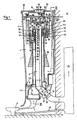
- a water flush essentially consists of a water tank (1), a flush line (2), a toilet bowl (3) and a quantity of flush water (4).
- the flushing line (2) is connected to a drain opening (5) which is recessed in a bottom (6) which closes off the water tank (1).
- the drain opening (5) is controlled by a drain valve (7) which is attached to a lower end of an inner tube (8) facing the bottom (6) and with a sealing washer (9) on a valve seat (5) provided in the drain opening (5). 10) rests when the drain valve (7) closes the drain opening (5).
- the inner tube (8) serves on the one hand to actuate the drain valve (7) as a valve rod.
- the inner tube (8) lies with its upper end facing away from the drain valve (7) in the immediate vicinity of an upper level (12) of the rinsing water (4) in the filled water tank (1).
- an exhaust air opening (13) is provided in the bottom (6) through which an air discharge (14) protrudes from an interior space (15) enclosed by the water tank (1) into the drain opening (5) and protrudes outside the interior space (15) below the base (6) from a connection sleeve (16) which is molded onto the base (6).
- the exhaust air opening (13) is connected to a fan (18) on its suction side (19). On its pressure side (20), the fan (18) opens into an exhaust system (22) via an exhaust pipe (21).
- This exhaust air system (22) can be designed as a waste water network, which is connected to the toilet bowl (3) via a waste water line (23).
- An electric motor (29) driving the fan (18) can be connected directly to the fan (18) and arranged with it in a housing (17) through which an exhaust air flow generated by the fan (18) flows.
- the water tank (1) is fastened with its rear wall (26) bounding it to a wall (27) supporting it, for example via hooks (28).
- a controller (30) is provided within the interior (15), with the aid of which the electric motor (29) can be switched on or off.
- This control (30) is connected to the electric motor (via a control line (31), which extends through the suction pipe (32) and is led out of the connecting sleeve (16) of the water box (1) at its end facing the floor (6). 29) connected.
- the control (30) can be designed as a reed contact (110) which, when a magnet (111) lying in its stroke path is reached, controls the control line (31) with a control pulse which switches on the electric motor (29).
- the air discharge (14) is designed as an exhaust pipe (32) connected to the exhaust air opening (13). This runs concentrically to the inner tube (8).
- the suction pipe (32) At its upper end (33) opposite the exhaust air opening (13), the suction pipe (32) has a fold (35) of its wall (34) with a U-shaped cross section.
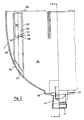
- This fold (35) has a free leg (36) which forms a sleeve which concentrically surrounds the upper end (33) of the suction pipe (32) and is releasably attached to it. With this free leg (36) the suction pipe (32) protrudes into a water trough (37) which concentrically surrounds the suction pipe (32).
- This water trough (37) is designed as an odor trap, which closes an interior (38) enclosed by the suction pipe (32) in an airtight manner with respect to the interior (15) of the water tank (1).
- This conclusion takes place with the help of an end cap (39) which rests with its bottom (40) with the odor trap closed on the upper end (33) of the suction pipe (32) and with its walls (41) concentrically surrounding the suction pipe (32)
- Water trough (37) protrudes.
- the walls (41) are so long that their ends (42) facing away from the bottom (40) protrude into a part of the water (43) standing in the water trough (37) when the bottom (40) is at the upper end (33) of the suction pipe (32) rests.
- the end cap (39) is movably mounted within the interior (15) in the longitudinal direction of the suction pipe (32).
- a right part of the end cap (39) is shown, for example, in a raised position, although the end cap (39) is actually not in two parts, but forms a unit.
- the lower end (42) of the wall (41) is lifted out of the partial water volume (43) of the water trough (37), so that between the raised end (42) and an upper level (44) of the partial water quantity (43) a free space is formed, through which an air flow is made possible from a space (45) lying outside the end cap (39) in the direction of the interior (38) of the suction pipe (32).
- a depression (113) which is curved in the direction of the interior (38) of the suction pipe (32) and in which the reed contact (110) of the control (30) lies.
- the magnet (111) is fastened in the stroke of this depression (113).
- the water trough (37) is formed on an upper end (46) of the inner tube (8) facing away from the drain valve (7).
- the inner tube (8) in the area of its upper end (46) with a widening (47) of its cross section hen.
- This widening is dimensioned so large that it can accommodate a water trough (37) receiving a U-shaped cross section of water pan (48) between an outer wall (49) delimiting widening (47) and an outer surface (50) facing it Suction tube (32) surrounds this concentrically.
- the water pan (48) is connected to the outer wall (49) via a connection (52) via its outer leg (51) facing the outer wall (49).
- This connection consists of short pipe sections (53) which extend between the outer wall (49) on the one hand and the outer leg (51) on the other and are firmly connected to both.
- the pipe sections (53) are dimensioned so long that between the outer wall (49) on the one hand and the outer leg (51) on the other hand, a free space (54) surrounding the suction pipe (32) remains, through which a space surrounded by the inner pipe (8) Interior (55) communicates with the room (45).
- At least two pipe sections (53) are distributed over the circumference of the water pan (48). Expediently, however, several pipe sections (53) are distributed over the circumference of the water trough (48) in order to stabilize it in the area of the upper end (46) of the inner pipe (8).
- the pipe sections (53) establish a connection between an interior space (56) enclosed by the water trough (48), in which the water trough (37) is formed, and the space (45).
- the pipe sections (53) open into the outer wall (49) at a height which is below the level (12) when the drain valve (7) is closed. In this way, care is taken to ensure that the rinsing water (4) can enter the water trough (37) through the connection (52) when the drain valve (7) is closed, so that any water loss occurring, for example, due to evaporation in the water trough (37) is compensated can be. This ensures that the water trough (37) is constantly filled.
- the ends (42) of the wall (41) immersed in the water trough (37) ensure constant water exchange in the water trough (37), which is replaced from the supply of the rinsing water (4).
- the water pan (48) projects with its inner leg (57) facing the suction pipe (32) into the annular space (58) formed by the free leg (36) of the fold (35) on the one hand and the outer surface (50) of the suction pipe (32) on the other hand .
- the length of the inner leg (57) is dimensioned such that its upper end (59) abuts a yoke (60) when the drain valve (7) is open, which yoke (60) connects the suction pipe (32) and the free leg ( 36) of the fold (35).
- the upper end (46) of the inner tube (8) is at a height which must not be exceeded even if a filler valve controlling the filling of the water tank (1) malfunctions.
- the end cap (39) is raised with the aid of an actuating mechanism (61), at the lower end (62) of which the end cap (39) is articulated. With the aid of this actuating mechanism (61), the end cap (39) can be moved within the space (45) which is surrounded by a cap (63).
- This has an approximately plane-parallel to the bottom (40) of the movable end cap (39) extending bottom (64), from which a wall (65) is approximately concentric to the wall (41) of the end cap (39) in the direction of the expansion (47) of the inner tube (8) extends.
- the cap (63) has a cross section which is dimensioned such that the wall (65) extends outside the outer wall (49) of the widening (47) and surrounds it concentrically.
- the length of the wall (65) is dimensioned such that its lower end (66), which faces the expansion (47), dips into the level (12) when the water tank is filled.
- the cap (63) is fastened in the region of its base (64) by anchors (67, 68, 69) to a crossmember (70) which extends across the interior (15) from the
- the rear wall (26) of the water tank (1) extends in the direction of which the front wall (71) runs opposite the rear wall (26) and stiffens this in relation to the rear wall (26). When the water tank (1) is full, the space (45) is sealed gas-tight with respect to the interior (15).
- the actuating mechanism (61) is passed through the bottom (64) of the cap (63) with an airtight seal (72) and ends with its upper end (73) opposite the lower end (62) in a two-armed rocker (74) which is pivotally mounted at its center on a trestle (75).
- This bracket (75) is fastened to the crossmember (70).
- the two-armed rocker (74) is articulated at one end (76) to the actuating mechanism (61) and at the other end (77) via a connecting lever (78) with an actuating button (79) which is movable vertically within one the water tank (1) is mounted opposite the bottom (6) closing cover (80).
- This cover (80) extends approximately plane-parallel above the cross member (70).
- the end (77) of the rocker (74) tilts when the operating button (79) is pressed towards the interior (15), as a result of which the end (76) of the rocker (74) lifts and the operating mechanism ( 61).
- the time during which the end cap (39) is raised is predetermined by a time control.
- This time control can be implemented as a time relay, not shown forms, which keeps the fan (18) switched on for a predetermined time, for example for 3 minutes, and keeps the end cap (39) locked in a raised position.
- the inner tube (8) is raised via an actuator (84).
- This actuating member (84) is connected on the one hand to the inner tube (8), for example in the area of the widening (47).
- the actuating element (84) is guided in the area of a passage (85) through the crossmember (70), on which a timer (86) is fastened in the immediate vicinity of the passage (85), with the aid of which the time for opening the inner tube ( 8) certain time is controlled.
- a rotary knob (91) which concentrically surrounds the actuating knob (79) can be rotated about its central axis.
- a float (96) can be attached to the inner tube (8). This can improve the buoyancy of the inner tube (8) within the rinse water (4).
- the actuation button (79) is first pressed. As a result, the end cap (39) is raised so that the passage from the interior (55) of the inner tube (8) through the space (45) below the cap (63) into the suction tube (32) is released.
- the electric motor (29) of the fan (18) is switched on by the movement of the actuating mechanism (61), so that a suction flow occurs within the interior (38) enclosed by the suction tube (32), which exhausts the exhaust air through the inner tube (8) sucks the toilet bowl (3) and presses it into the exhaust system (22).
- the rotary knob (91) is turned into a position in which it releases the flushing water quantity (4) required for the flushing required in each case.
- the rotary knob (91) is then pressed in the direction of the interior (15) and the actuating member (84) is thus raised. With it, the inner tube (8) lifts and thus releases the drain valve (7) so that the flushing water (4) can flow out of the interior (15) into the toilet bowl (3).
- the fan (18) is switched off in that the end cap (39) sinks into the water trough (37) with its lower end (42) due to its own weight.
- the time at which the end cap (39) is released from a lock holding it in the raised state is controlled by the time control. If a time set on the time control designed as a time relay is not sufficient for the extraction of the exhaust air, the actuating button (79) must be actuated a second time.
- the inner tube (8) also drops due to its own weight in the direction of the drain valve (7) after it has first been raised.
- the sinking time depends on the time control (86).
- This suspension (99) consists of a link (100) receiving the hook (28), behind which the hook grips with its upright end (101) protruding from the wall (27).
- This link (100) is designed as a relatively narrow plastic strip (102) which is mounted in a longitudinally displaceable manner in a guide (103) arranged on the rear wall (26).
- This guide (103) is closed on an upper edge (104) of the water tank (1) facing the cover (80). It extends in the vertical direction over the rear wall (26) into a side wall (105) delimiting the water tank (1).
- the guide (103) is closed with a stopper (107) which, as a screen, adapts seamlessly to the course of the side wall (105).
- the guide (103) is open in the direction of the wall (27) so that any hooks protruding from the wall (27) can protrude into the guide (103).
- the backdrop is supported, the length of which is dimensioned up to its lower end (108) in such a way that the water tank (1) is aligned on the wall (27) in a desired position when the Hook (28) over the lower end (108) of the plastic strip (102) grips.
- parts can be removed from the plastic strip (102) until the water box (101) rests on the hook (28) in such a way that the level (12) is horizontal.
- At least two guides (103) expediently extend over the rear wall (26).
Landscapes
- Health & Medical Sciences (AREA)
- Public Health (AREA)
- Epidemiology (AREA)
- Life Sciences & Earth Sciences (AREA)
- Engineering & Computer Science (AREA)
- Hydrology & Water Resources (AREA)
- Water Supply & Treatment (AREA)
- Sanitary Device For Flush Toilet (AREA)
- Non-Flushing Toilets (AREA)
Applications Claiming Priority (2)
| Application Number | Priority Date | Filing Date | Title |
|---|---|---|---|
| DE3907214A DE3907214A1 (de) | 1989-03-07 | 1989-03-07 | Wasserspuelung |
| DE3907214 | 1989-03-07 |
Publications (2)
| Publication Number | Publication Date |
|---|---|
| EP0386539A2 true EP0386539A2 (fr) | 1990-09-12 |
| EP0386539A3 EP0386539A3 (fr) | 1991-12-11 |
Family
ID=6375667
Family Applications (1)
| Application Number | Title | Priority Date | Filing Date |
|---|---|---|---|
| EP19900103436 Ceased EP0386539A3 (fr) | 1989-03-07 | 1990-02-22 | Chasse d'eau |
Country Status (3)
| Country | Link |
|---|---|
| US (1) | US4998299A (fr) |
| EP (1) | EP0386539A3 (fr) |
| DE (1) | DE3907214A1 (fr) |
Cited By (1)
| Publication number | Priority date | Publication date | Assignee | Title |
|---|---|---|---|---|
| WO1999054563A1 (fr) * | 1998-04-21 | 1999-10-28 | Blackborow, John | Vanne de refoulement de citerne |
Families Citing this family (8)
| Publication number | Priority date | Publication date | Assignee | Title |
|---|---|---|---|---|
| DE3927200A1 (de) * | 1989-08-17 | 1991-02-21 | Heinrich Menge | Spuelkasten |
| US5369813A (en) * | 1993-12-10 | 1994-12-06 | Goddard; Lewis W. | Self-contained toilet venting system |
| GB2319268B (en) * | 1996-11-07 | 2000-11-15 | Michael Graham Nichola Hawkins | Ventilation and flushing unit for a toilet |
| WO2008025051A1 (fr) * | 2006-08-29 | 2008-03-06 | Morris, Elaine, K. | Système d'évacuation d'air pour toilettes |
| US20100257667A1 (en) * | 2009-04-10 | 2010-10-14 | James Kennedy | Ventilated Toilet |
| US8505123B2 (en) * | 2009-04-10 | 2013-08-13 | Havilah Holdings (Thunder Bay) Corp. | Ventilated toilet |
| CN101798840A (zh) * | 2010-02-26 | 2010-08-11 | 温州劲洁卫浴科技有限公司 | 一种消除便臭异味的马桶水件 |
| US9809965B1 (en) | 2016-05-11 | 2017-11-07 | Robert Trudel | Toilet having a built-in odor evacuating system |
Family Cites Families (14)
| Publication number | Priority date | Publication date | Assignee | Title |
|---|---|---|---|---|
| US1303974A (en) * | 1919-05-20 | shadall | ||
| US288573A (en) * | 1883-11-13 | James p | ||
| US516011A (en) * | 1894-03-06 | Water-closet tank | ||
| US680380A (en) * | 1900-10-13 | 1901-08-13 | Mary A Hide | Means for preserving seals in traps of water-closets, urinals, washbasins, sinks, &c. |
| US1342716A (en) * | 1917-12-10 | 1920-06-08 | Edwin A Johnston | Closet-ventilator |
| AT313194B (de) * | 1970-07-30 | 1974-02-11 | Gaggenau Eisenwerk | Deckeleinheit für Abortspülkästen |
| DE2114778C3 (de) * | 1971-03-26 | 1980-05-08 | Schwab Sanitaer-Plastic Gmbh, 7417 Pfullingen | Vorrichtung zur Schlechtluftabsaugung aus einem Klosettbecken |
| US3740771A (en) * | 1971-05-12 | 1973-06-26 | J Bond | Air venting device for a toilet |
| SE418516B (sv) * | 1979-05-16 | 1981-06-09 | Lagerstedt & Krantz Ab | Ventilationsanordning vid vattenklosett |
| US4318192A (en) * | 1979-10-31 | 1982-03-09 | Williams Jack D | Ventilated toilet |
| ATE80190T1 (de) * | 1985-07-25 | 1992-09-15 | Heinrich Menge | Vorrichtung zum steuern mindestens eines gasstromes. |
| DE3631595A1 (de) * | 1986-09-17 | 1988-03-24 | Heinrich Menge | Vorrichtung zum steuern mindestens eines gasstromes |
| DE3643043A1 (de) * | 1986-12-17 | 1988-06-30 | Heinrich Menge | Verfahren und vorrichtung zum steuern mindestens eines gasstromes |
| US4933996A (en) * | 1989-05-25 | 1990-06-19 | Sowards Edward W | Toilet deodorizer |
-
1989
- 1989-03-07 DE DE3907214A patent/DE3907214A1/de not_active Withdrawn
-
1990
- 1990-02-22 EP EP19900103436 patent/EP0386539A3/fr not_active Ceased
- 1990-03-06 US US07/491,478 patent/US4998299A/en not_active Expired - Fee Related
Cited By (1)
| Publication number | Priority date | Publication date | Assignee | Title |
|---|---|---|---|---|
| WO1999054563A1 (fr) * | 1998-04-21 | 1999-10-28 | Blackborow, John | Vanne de refoulement de citerne |
Also Published As
| Publication number | Publication date |
|---|---|
| DE3907214A1 (de) | 1990-09-13 |
| EP0386539A3 (fr) | 1991-12-11 |
| US4998299A (en) | 1991-03-12 |
Similar Documents
| Publication | Publication Date | Title |
|---|---|---|
| EP0488997B1 (fr) | Gicleur pour baignoire à tourbillonnement d'eau, notamment pour baignoire comprenant un système de prérinçage automatique | |
| EP0453804B1 (fr) | Filtre pour aquarium | |
| EP0219622A2 (fr) | Dispositif pour contrôler au moins un courant de gaz | |
| EP0673601B1 (fr) | Filtre pour aquariums | |
| DE19631078A1 (de) | Verfahren zur Reinigung von Toilettenbecken | |
| DE3907214A1 (de) | Wasserspuelung | |
| EP0278092B1 (fr) | Méthode et dispositif pour contrôler un courant de gaz | |
| EP0332090B1 (fr) | Appareil pour aspirer et évacuer un liquide contenant des matières nocives notamment de l'eau sale | |
| DE2522425C3 (de) | Bodenablauf mit Genichverschluß für Abwasserbehälter | |
| DE202024102164U1 (de) | Roboter-Basisstation und Robotersystem | |
| DE19903952C2 (de) | Klosettbeckenentlüftung | |
| DE2702639A1 (de) | Toilettenspuelkasten | |
| DE2611604C2 (de) | Vorrichtung zur Begrenzung des Wasserauslaufes aus Wasserbehältern mit einem Bodenauslauf | |
| DE2037625B2 (de) | Desodierungsvorrichtung | |
| DE3522642A1 (de) | Toilettenbecken | |
| DE4212708A1 (de) | Selbsttätig wirkende Hebervorrichtung | |
| DE3526587A1 (de) | Vorrichtung zum steuern mindestens eines gasstromes | |
| EP0512157B1 (fr) | Séparateur | |
| DE8122304U1 (de) | "Vorrichtung zum Spülen und Desinfizieren" | |
| DE3631595A1 (de) | Vorrichtung zum steuern mindestens eines gasstromes | |
| DE900199C (de) | Verfahren zur Desinfizierung von Spuelaborten, Pissoiranlagen und aehnlichen sanitaeren Einrichtungen sowie Fluessigkeitszusetzapparat zur Ausfuehrung des Verfahrens | |
| DE69927952T2 (de) | Verbesserte vorrichtung und verfahren zum entfernen von toilettengerüchen | |
| WO1990010122A1 (fr) | Distributeur automatique de quantites definies de substances actives dans des cuvettes de toilettes, commande par la chasse d'eau | |
| DE2629126C2 (de) | Vorrichtung zur Begrenzung des Wasserauslaufes aus Wasserbehältern, insbesondere aus Spülkästen für Toiletten | |
| DE1238858B (de) | Anordnung zum Abfuehren von Klosettabwaessern aus Haeusern |
Legal Events
| Date | Code | Title | Description |
|---|---|---|---|
| PUAI | Public reference made under article 153(3) epc to a published international application that has entered the european phase |
Free format text: ORIGINAL CODE: 0009012 |
|
| AK | Designated contracting states |
Kind code of ref document: A2 Designated state(s): AT BE CH DE DK ES FR GB GR IT LI LU NL SE |
|
| RBV | Designated contracting states (corrected) |
Designated state(s): CH DE FR GB IT LI NL SE |
|
| 17P | Request for examination filed |
Effective date: 19901231 |
|
| PUAL | Search report despatched |
Free format text: ORIGINAL CODE: 0009013 |
|
| AK | Designated contracting states |
Kind code of ref document: A3 Designated state(s): AT BE CH DE DK ES FR GB GR IT LI LU NL SE |
|
| 17Q | First examination report despatched |
Effective date: 19920928 |
|
| STAA | Information on the status of an ep patent application or granted ep patent |
Free format text: STATUS: THE APPLICATION HAS BEEN REFUSED |
|
| 18R | Application refused |
Effective date: 19940919 |