EP0386647B1 - a damping means for pressure shocks in sanitary fittings - Google Patents
a damping means for pressure shocks in sanitary fittings Download PDFInfo
- Publication number
- EP0386647B1 EP0386647B1 EP90104062A EP90104062A EP0386647B1 EP 0386647 B1 EP0386647 B1 EP 0386647B1 EP 90104062 A EP90104062 A EP 90104062A EP 90104062 A EP90104062 A EP 90104062A EP 0386647 B1 EP0386647 B1 EP 0386647B1
- Authority
- EP
- European Patent Office
- Prior art keywords
- pressure
- damping means
- chambers
- openings
- faucet
- Prior art date
- Legal status (The legal status is an assumption and is not a legal conclusion. Google has not performed a legal analysis and makes no representation as to the accuracy of the status listed.)
- Expired - Lifetime
Links
- 238000013016 damping Methods 0.000 title claims abstract description 29
- 230000035939 shock Effects 0.000 title claims abstract description 28
- XLYOFNOQVPJJNP-UHFFFAOYSA-N water Substances O XLYOFNOQVPJJNP-UHFFFAOYSA-N 0.000 claims abstract description 19
- 238000005553 drilling Methods 0.000 claims description 3
- 229910001220 stainless steel Inorganic materials 0.000 claims description 3
- 239000010935 stainless steel Substances 0.000 claims description 3
- 230000000694 effects Effects 0.000 description 2
- 239000000463 material Substances 0.000 description 1
Images
Classifications
-
- F—MECHANICAL ENGINEERING; LIGHTING; HEATING; WEAPONS; BLASTING
- F16—ENGINEERING ELEMENTS AND UNITS; GENERAL MEASURES FOR PRODUCING AND MAINTAINING EFFECTIVE FUNCTIONING OF MACHINES OR INSTALLATIONS; THERMAL INSULATION IN GENERAL
- F16K—VALVES; TAPS; COCKS; ACTUATING-FLOATS; DEVICES FOR VENTING OR AERATING
- F16K47/00—Means in valves for absorbing fluid energy
- F16K47/02—Means in valves for absorbing fluid energy for preventing water-hammer or noise
-
- E—FIXED CONSTRUCTIONS
- E03—WATER SUPPLY; SEWERAGE
- E03C—DOMESTIC PLUMBING INSTALLATIONS FOR FRESH WATER OR WASTE WATER; SINKS
- E03C1/00—Domestic plumbing installations for fresh water or waste water; Sinks
- E03C1/02—Plumbing installations for fresh water
- E03C1/04—Water-basin installations specially adapted to wash-basins or baths
Definitions
- the present invention relates to a damping means for pressure shocks to be used in sanitary fittings, which reduces pressure shocks exerted on the pipework by the closing of the sanitary fitting.
- lever faucets in which both the amount and the temperature of water is adjusted by one single lever.
- a net pressure shock of approx. 1,6 106 Pa (16 bars) is produced in the pipework, susceptible of damaging the sanitary fitting itself or the connection between this and the water pipework.
- Previously one tried to dampen these pressure shocks by mounting an elastic rubber ring at an appropriate point of the sanitary fitting.
- this solution has proved to be unsufficiently effective.
- the purpose of the present invention is to provide a more effective damping means for pressure shocks, which is easy to install. According to the invention, this has been achieved by mounting a kind of safety valve on the faucet body, the opening pressure of which is 106 Pa (10 bars).
- the damping means for pressure shocks according to the invention is mounted on the faucet body as close as possible to the closing point, thus enabling it to react on quick pressure shocks.
- This damping means for pressure shocks also has the advantage of protecting, besides the pipework, the service pipes of the faucet, as well as the connection between the pipework and the faucet from pressure shocks.
- the pressure damping means comprises a plate having openings for hot and cold water flow to the adjusting assembly. In the walls of these openings a connection with the chambers of the pressure damping means is provided, the actual pressure damping members being positioned in these chambers. These members consist of a spring, at the end of which a ball has been placed. The ball closes the flow connection to the cold and hot water pipes. In the case of a pressure shock, the spring retracts and the ball withdraws from the mouth of the passage letting in water into the pressure damping chamber. The water is discharged from the chamber into the outlet pipe leading to the supply pipe of the faucet as the damping means for pressure shocks is opened. Under these circumstances, no supplementary drain connection is needed.
- the mobile parts of the damping means for pressure shocks are made of a material that is as light as possible, e.g. of stainless steel and/or plastic.
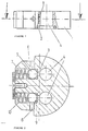
- figure 1 shows a side perspective of the damping means for pressure shocks
- figure 2 shows a top view of the damping means for pressure shocks
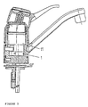
- figure 3 shows the position of the damping means for pressure shocks in a lever faucet.
- Figure 1 illustrates a pressure damper having a plate-shaped body 1.
- the cold and hot water passages 4 pass through the body 1, the passages being sealed by means of O-rings 2. Openings 3, through which water can flow to the chambers of the pressure damper, are provided in the wall of the hot and cold water passages 4.
- the pressure damper of the invention is shown from above, showing the passages 4 of both hot and cold water.
- a pressure shock water flows through the openings 3 into the chambers 10 of the pressure damper, which are for med of drillings perpendicular to the connections, and in which the actual pressure damping members 5 and 7 are placed.
- the pressure damping members consist of a spring 7 and of a ball 5 supported by one end of the spring. Under the effect of a pressure shock the spring 7 retracts, whereby the ball 5 withdraws from the opening 3 letting in water.
- an outlet pipe 8 is provided, which opens into a slot 6 in the body of the damping means. The water discharged through the opening 3 under the effect of a pressure shock is removed through the outlet pipe 8 and the slot 6 into the supply pipe of the faucet.
- the ball 5 of the pressure damping means 5, 7 is sealed with the O-ring 9.
- Figure 3 shows the position of the pressure damping means 1 in a lever faucet below the adjusting assembly 11.
Landscapes
- Engineering & Computer Science (AREA)
- General Engineering & Computer Science (AREA)
- Mechanical Engineering (AREA)
- Health & Medical Sciences (AREA)
- Life Sciences & Earth Sciences (AREA)
- Hydrology & Water Resources (AREA)
- Public Health (AREA)
- Water Supply & Treatment (AREA)
- Pipe Accessories (AREA)
- Dowels (AREA)
- Percussive Tools And Related Accessories (AREA)
- Surgical Instruments (AREA)
- Processing Of Solid Wastes (AREA)
- Domestic Plumbing Installations (AREA)
- Absorbent Articles And Supports Therefor (AREA)
- Details Of Valves (AREA)
- Multiple-Way Valves (AREA)
- Navigation (AREA)
Applications Claiming Priority (2)
| Application Number | Priority Date | Filing Date | Title |
|---|---|---|---|
| FI891084A FI891084A7 (fi) | 1989-03-07 | 1989-03-07 | Tryckstoetsutjaemnare foer vattenarmaturer. |
| FI891084 | 1989-03-07 |
Publications (2)
| Publication Number | Publication Date |
|---|---|
| EP0386647A1 EP0386647A1 (en) | 1990-09-12 |
| EP0386647B1 true EP0386647B1 (en) | 1993-07-28 |
Family
ID=8528010
Family Applications (1)
| Application Number | Title | Priority Date | Filing Date |
|---|---|---|---|
| EP90104062A Expired - Lifetime EP0386647B1 (en) | 1989-03-07 | 1990-03-02 | a damping means for pressure shocks in sanitary fittings |
Country Status (7)
| Country | Link |
|---|---|
| EP (1) | EP0386647B1 (da) |
| AT (1) | ATE92164T1 (da) |
| DE (1) | DE69002350T2 (da) |
| DK (1) | DK0386647T3 (da) |
| ES (1) | ES2044271T3 (da) |
| FI (1) | FI891084A7 (da) |
| NO (1) | NO901047L (da) |
Families Citing this family (3)
| Publication number | Priority date | Publication date | Assignee | Title |
|---|---|---|---|---|
| US5894862A (en) * | 1997-01-30 | 1999-04-20 | Vickers, Incorporated | Hydraulic damper |
| IT1319953B1 (it) * | 2000-03-10 | 2003-11-12 | Hesa S R L | Gruppo rubinetteria a tre elementi. |
| CN109139938B (zh) * | 2018-10-24 | 2020-03-20 | 温州职业技术学院 | 一种截止阀 |
Family Cites Families (2)
| Publication number | Priority date | Publication date | Assignee | Title |
|---|---|---|---|---|
| US3677295A (en) * | 1971-02-01 | 1972-07-18 | Applied Power Ind Inc | Directional valve control |
| US4049019A (en) * | 1976-09-13 | 1977-09-20 | Owatonna Tool Company | Rotary valve |
-
1989
- 1989-03-07 FI FI891084A patent/FI891084A7/fi not_active Application Discontinuation
-
1990
- 1990-03-02 AT AT90104062T patent/ATE92164T1/de not_active IP Right Cessation
- 1990-03-02 EP EP90104062A patent/EP0386647B1/en not_active Expired - Lifetime
- 1990-03-02 DE DE90104062T patent/DE69002350T2/de not_active Expired - Lifetime
- 1990-03-02 ES ES90104062T patent/ES2044271T3/es not_active Expired - Lifetime
- 1990-03-02 DK DK90104062.6T patent/DK0386647T3/da active
- 1990-03-06 NO NO90901047A patent/NO901047L/no unknown
Also Published As
| Publication number | Publication date |
|---|---|
| FI891084A0 (fi) | 1989-03-07 |
| NO901047D0 (no) | 1990-03-06 |
| NO901047L (no) | 1990-09-10 |
| ATE92164T1 (de) | 1993-08-15 |
| EP0386647A1 (en) | 1990-09-12 |
| FI891084A7 (fi) | 1990-09-08 |
| DE69002350T2 (de) | 1993-11-04 |
| ES2044271T3 (es) | 1994-01-01 |
| DK0386647T3 (da) | 1993-09-27 |
| DE69002350D1 (de) | 1993-09-02 |
Similar Documents
| Publication | Publication Date | Title |
|---|---|---|
| CA2076924A1 (en) | Integral Check, Pressure Balanced, Control Valve | |
| CA2356525A1 (en) | Motorized valve actuating device | |
| GB9925648D0 (en) | Improvements in valves | |
| AU3513895A (en) | Valve for a system having a heat carrying medium | |
| EP0386647B1 (en) | a damping means for pressure shocks in sanitary fittings | |
| US4979539A (en) | Sanitary mixing valve | |
| CA2013260C (en) | A device against siphon back flow, for hydraulic valves having a cartridge with plane plates for flux control | |
| AU632201B2 (en) | Water tap fitting with reverse-suction prevention | |
| EP0819474A3 (de) | Steureinrichtung für ein Fluid, wie Wasser | |
| CA2156811A1 (en) | Sanitary Fitting | |
| CA2406488A1 (en) | Combination poppet and gate valve | |
| KR200151567Y1 (ko) | 수도전용 자폐식 밸브장치 | |
| EP0684416A1 (en) | Hot and cold water mixer valve with built-in anti-backflow device | |
| US4896691A (en) | Pressure compensating device | |
| CA2330002A1 (en) | Water hammering prevention device | |
| EP0386613B1 (en) | A mixing valve with means for slowing down the closing action | |
| GB2216239A (en) | Ventilating device for fittings | |
| AU642438B2 (en) | Improved pilot operated valve | |
| KR200161210Y1 (ko) | 체크밸브 | |
| EP1097635A3 (de) | Vorrichtung zum Ausgleich des Drucks einer Flüssigkeit und Verfahren zur Änderung des Druckausgleichsverhältnisses | |
| EP0322597A3 (en) | Single handle mixing valve with a pressure relief device | |
| KR0131527Y1 (ko) | 정수위 조절 밸브 | |
| KR950004113Y1 (ko) | 정유량 역지밸브 | |
| CA2192763A1 (en) | Control valve for use in a dual handled hot/cold water mixing faucet | |
| JPS5757976A (en) | Solenoid valve |
Legal Events
| Date | Code | Title | Description |
|---|---|---|---|
| PUAI | Public reference made under article 153(3) epc to a published international application that has entered the european phase |
Free format text: ORIGINAL CODE: 0009012 |
|
| AK | Designated contracting states |
Kind code of ref document: A1 Designated state(s): AT BE CH DE DK ES FR GB GR IT LI LU NL SE |
|
| 17P | Request for examination filed |
Effective date: 19901220 |
|
| 17Q | First examination report despatched |
Effective date: 19921005 |
|
| GRAA | (expected) grant |
Free format text: ORIGINAL CODE: 0009210 |
|
| AK | Designated contracting states |
Kind code of ref document: B1 Designated state(s): AT BE CH DE DK ES FR GB GR IT LI LU NL SE |
|
| PG25 | Lapsed in a contracting state [announced via postgrant information from national office to epo] |
Ref country code: GR Free format text: LAPSE BECAUSE OF FAILURE TO SUBMIT A TRANSLATION OF THE DESCRIPTION OR TO PAY THE FEE WITHIN THE PRESCRIBED TIME-LIMIT Effective date: 19930728 |
|
| REF | Corresponds to: |
Ref document number: 92164 Country of ref document: AT Date of ref document: 19930815 Kind code of ref document: T |
|
| REF | Corresponds to: |
Ref document number: 69002350 Country of ref document: DE Date of ref document: 19930902 |
|
| REG | Reference to a national code |
Ref country code: DK Ref legal event code: T3 |
|
| ET | Fr: translation filed | ||
| ITF | It: translation for a ep patent filed | ||
| REG | Reference to a national code |
Ref country code: ES Ref legal event code: FG2A Ref document number: 2044271 Country of ref document: ES Kind code of ref document: T3 |
|
| PLBE | No opposition filed within time limit |
Free format text: ORIGINAL CODE: 0009261 |
|
| STAA | Information on the status of an ep patent application or granted ep patent |
Free format text: STATUS: NO OPPOSITION FILED WITHIN TIME LIMIT |
|
| EPTA | Lu: last paid annual fee | ||
| 26N | No opposition filed | ||
| EAL | Se: european patent in force in sweden |
Ref document number: 90104062.6 |
|
| REG | Reference to a national code |
Ref country code: GB Ref legal event code: IF02 |
|
| PGFP | Annual fee paid to national office [announced via postgrant information from national office to epo] |
Ref country code: AT Payment date: 20090325 Year of fee payment: 20 Ref country code: ES Payment date: 20090324 Year of fee payment: 20 Ref country code: LU Payment date: 20090323 Year of fee payment: 20 Ref country code: DK Payment date: 20090324 Year of fee payment: 20 |
|
| PGFP | Annual fee paid to national office [announced via postgrant information from national office to epo] |
Ref country code: NL Payment date: 20090324 Year of fee payment: 20 |
|
| PGFP | Annual fee paid to national office [announced via postgrant information from national office to epo] |
Ref country code: CH Payment date: 20090317 Year of fee payment: 20 Ref country code: GB Payment date: 20090331 Year of fee payment: 20 |
|
| PGFP | Annual fee paid to national office [announced via postgrant information from national office to epo] |
Ref country code: BE Payment date: 20090320 Year of fee payment: 20 |
|
| PGFP | Annual fee paid to national office [announced via postgrant information from national office to epo] |
Ref country code: SE Payment date: 20090325 Year of fee payment: 20 Ref country code: DE Payment date: 20090324 Year of fee payment: 20 Ref country code: IT Payment date: 20090319 Year of fee payment: 20 Ref country code: FR Payment date: 20090331 Year of fee payment: 20 |
|
| REG | Reference to a national code |
Ref country code: CH Ref legal event code: PL |
|
| REG | Reference to a national code |
Ref country code: NL Ref legal event code: V4 Effective date: 20100302 |
|
| REG | Reference to a national code |
Ref country code: DK Ref legal event code: EUP |
|
| REG | Reference to a national code |
Ref country code: GB Ref legal event code: PE20 Expiry date: 20100301 |
|
| BE20 | Be: patent expired |
Owner name: *ORAS OY Effective date: 20100302 |
|
| EUG | Se: european patent has lapsed | ||
| REG | Reference to a national code |
Ref country code: ES Ref legal event code: FD2A Effective date: 20100303 |
|
| PG25 | Lapsed in a contracting state [announced via postgrant information from national office to epo] |
Ref country code: GB Free format text: LAPSE BECAUSE OF EXPIRATION OF PROTECTION Effective date: 20100301 |
|
| PG25 | Lapsed in a contracting state [announced via postgrant information from national office to epo] |
Ref country code: NL Free format text: LAPSE BECAUSE OF EXPIRATION OF PROTECTION Effective date: 20100302 Ref country code: ES Free format text: LAPSE BECAUSE OF EXPIRATION OF PROTECTION Effective date: 20100303 |
|
| PG25 | Lapsed in a contracting state [announced via postgrant information from national office to epo] |
Ref country code: DE Free format text: LAPSE BECAUSE OF EXPIRATION OF PROTECTION Effective date: 20100302 |