EP0386813A2 - Vorrichtung zum axialen Ein- und Ausspannen von Holzstämmen in Furnierscheidmaschinen - Google Patents
Vorrichtung zum axialen Ein- und Ausspannen von Holzstämmen in Furnierscheidmaschinen Download PDFInfo
- Publication number
- EP0386813A2 EP0386813A2 EP90200378A EP90200378A EP0386813A2 EP 0386813 A2 EP0386813 A2 EP 0386813A2 EP 90200378 A EP90200378 A EP 90200378A EP 90200378 A EP90200378 A EP 90200378A EP 0386813 A2 EP0386813 A2 EP 0386813A2
- Authority
- EP
- European Patent Office
- Prior art keywords
- log
- teeth
- shaft
- wood
- veneer cutting
- Prior art date
- Legal status (The legal status is an assumption and is not a legal conclusion. Google has not performed a legal analysis and makes no representation as to the accuracy of the status listed.)
- Granted
Links
Images

Classifications
-
- B—PERFORMING OPERATIONS; TRANSPORTING
- B27—WORKING OR PRESERVING WOOD OR SIMILAR MATERIAL; NAILING OR STAPLING MACHINES IN GENERAL
- B27L—REMOVING BARK OR VESTIGES OF BRANCHES; SPLITTING WOOD; MANUFACTURE OF VENEER, WOODEN STICKS, WOOD SHAVINGS, WOOD FIBRES OR WOOD POWDER
- B27L5/00—Manufacture of veneer ; Preparatory processing therefor
- B27L5/02—Cutting strips from a rotating trunk or piece; Veneer lathes
Definitions
- This invention refers to a device for engaging and disengaging claws axially gripping a log of wood inserted in a veneer cutting machine.
- Said claws are axially movable so as to enable them to move away from and towards the ends of the log and thus keep it secured to the spindles during the cutting and, at the end of the operation, to release the remaining core of wood which is conveyed away from the machine in order to make room for the next log.
- the general scope of this invention is to obviate the aforementioned problem by providing devices which ensure efficient disengagement of the gripping claws from the ends of the residual core of wood in veneer cutting machines.
- a device for axial engagement and disengagement of one end of a log of wood rotating in a veneer cutting machine of the type comprising a claw, having a plurality of teeth which penetrate into the wood, disposed on a shaft which rotates by means of a coupling with a spindle in which said shaft slides axially from a first position in which the teeth penetrate the log to a second position in which the teeth are removed from the log, in order to insert the teeth into the end of the log and thus cause it to rotate for the veneer cutting operations while cooperating with a similar device at the other end of the log, characterized by the fact that disposed coaxially to said claw is a pusher which is positively movable, by means of actuators, from a retracted position in which it does not interfere with the log penetrated by the teeth to an extracted position in which it pushes the log away from said teeth during the substantially simultaneous movement of the shaft from said first to said second position.
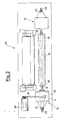
- a device for engaging and disengaging a plurality of teeth 10 of a claw 13 in one end of a log 14 comprises a shaft 15 carrying the claw 13 and fitted, slidingly but not rotatingly, by means of a splined profile 16, into couplings 24 in a spindle 18.
- the spindle 18 in turn is housed, by means of bearings 17 and 19, in a supporting upright secured to the floor.
- the shaft 15 is axially movable by known traversing means (for example hydraulic), not shown, to enable the gripping claws to carry out said known movement towards and away from the end of the log.
- known traversing means for example hydraulic
- a single-acting piston 20 hydraulically or pneumatically operated by means of a duct 21 inside the shaft 15 and connected by means of a rotating joint 23 of known technique to a supply system which is not shown since it can be of any known type.
- the shaft 15 is free to rotate driven by the spindle 18 which, in order to rotate, is connected to a pulley 25 coaxial thereto.
- the piston 20 acts upon a pusher 22 which passes axially through the claw 13 between the teeth 10.
- the device 12 and a device 12′ of identical structure form an integral part of a veneer cutting machine 26 the remainder of which is made according to the known technique and is therefore neither described nor drawn in detail.
- the two devices 12, 12′ are disposed at both ends of the log 14 and the device 12 is provided with a coupling 27 between the pulley 25 and an electric motor 28.
- the device 12′ Since the device 12′ is not connected to driving mechanisms, obviously, it need not necessarily be provided with the pulley 25.
- the shafts 15, 15′ are pushed by the known traversing means so that the teeth of the claws 13, 13′ engage in the ends of the log positioned between them so that the spindle 18 can drive it round when the motor 28 is turned on for the veneer cutting operations.
- the shafts 15, 15′ retract and at the same time the pistons inside them are fed so as to operate the pushers in the claws which exert pressure on the ends of the log thus reliably disengaging it from the teeth 10, 10′.
- the device is thus able to exert all the necessary force to disengage the teeth of the claws from the wood without, however, reducing in any way whatsoever the force available for penetration of the teeth in order to secure the log.
- the mechanisms transmitting motion to the spindle 18 may be of any type known to the technician and not necessarily belts and pulleys as shown in the figures.
- the means for preventing relative rotatory movement between the spindle and the sliding shaft may also be different, as is easily imaginable by any technician expert in the field.
Landscapes
- Engineering & Computer Science (AREA)
- Life Sciences & Earth Sciences (AREA)
- Manufacturing & Machinery (AREA)
- Wood Science & Technology (AREA)
- Forests & Forestry (AREA)
- Manufacture Of Wood Veneers (AREA)
- Medicines Containing Plant Substances (AREA)
- Debarking, Splitting, And Disintegration Of Timber (AREA)
Applications Claiming Priority (2)
| Application Number | Priority Date | Filing Date | Title |
|---|---|---|---|
| IT2071889U | 1989-03-10 | ||
| IT8920718U IT215761Z2 (it) | 1989-03-10 | 1989-03-10 | Dispositivo di innesto e disinnesto assiale di tronchi di legno in macchine sfogliatrici. |
Publications (3)
| Publication Number | Publication Date |
|---|---|
| EP0386813A2 true EP0386813A2 (de) | 1990-09-12 |
| EP0386813A3 EP0386813A3 (de) | 1991-11-13 |
| EP0386813B1 EP0386813B1 (de) | 1994-01-05 |
Family
ID=11171038
Family Applications (1)
| Application Number | Title | Priority Date | Filing Date |
|---|---|---|---|
| EP90200378A Expired - Lifetime EP0386813B1 (de) | 1989-03-10 | 1990-02-16 | Vorrichtung zum axialen Ein- und Ausspannen von Holzstämmen in Furnierscheidmaschinen |
Country Status (7)
| Country | Link |
|---|---|
| EP (1) | EP0386813B1 (de) |
| AT (1) | ATE99589T1 (de) |
| DE (1) | DE69005667T2 (de) |
| DK (1) | DK0386813T3 (de) |
| ES (1) | ES2049401T3 (de) |
| FI (1) | FI901172A7 (de) |
| IT (1) | IT215761Z2 (de) |
Cited By (1)
| Publication number | Priority date | Publication date | Assignee | Title |
|---|---|---|---|---|
| WO2004094121A1 (de) * | 2002-12-13 | 2004-11-04 | Grenzebach Bsh Gmbh | Furniermessermaschine |
Family Cites Families (3)
| Publication number | Priority date | Publication date | Assignee | Title |
|---|---|---|---|---|
| US2194391A (en) * | 1939-03-08 | 1940-03-19 | Jabez N Ingalsbe | Driving head for lathes |
| US3176735A (en) * | 1961-08-22 | 1965-04-06 | Coe Mfg Co | Veneer lathe |
| US4603744A (en) * | 1984-11-01 | 1986-08-05 | Ramirez Frank L | Weed extractor device |
-
1989
- 1989-03-10 IT IT8920718U patent/IT215761Z2/it active
-
1990
- 1990-02-16 ES ES90200378T patent/ES2049401T3/es not_active Expired - Lifetime
- 1990-02-16 AT AT90200378T patent/ATE99589T1/de active
- 1990-02-16 EP EP90200378A patent/EP0386813B1/de not_active Expired - Lifetime
- 1990-02-16 DE DE69005667T patent/DE69005667T2/de not_active Expired - Fee Related
- 1990-02-16 DK DK90200378.9T patent/DK0386813T3/da active
- 1990-03-08 FI FI901172A patent/FI901172A7/fi not_active Application Discontinuation
Cited By (2)
| Publication number | Priority date | Publication date | Assignee | Title |
|---|---|---|---|---|
| WO2004094121A1 (de) * | 2002-12-13 | 2004-11-04 | Grenzebach Bsh Gmbh | Furniermessermaschine |
| US7100650B2 (en) * | 2002-12-13 | 2006-09-05 | Grenzebach-Bsh Gmbh | Veneer slicer |
Also Published As
| Publication number | Publication date |
|---|---|
| EP0386813A3 (de) | 1991-11-13 |
| IT8920718V0 (it) | 1989-03-10 |
| ATE99589T1 (de) | 1994-01-15 |
| DE69005667T2 (de) | 1994-05-19 |
| DK0386813T3 (da) | 1994-01-31 |
| IT215761Z2 (it) | 1990-11-05 |
| FI901172A7 (fi) | 1990-09-11 |
| ES2049401T3 (es) | 1994-04-16 |
| FI901172A0 (fi) | 1990-03-08 |
| EP0386813B1 (de) | 1994-01-05 |
| DE69005667D1 (de) | 1994-02-17 |
Similar Documents
| Publication | Publication Date | Title |
|---|---|---|
| US4657453A (en) | Milling device with universal gear and automatic indexation | |
| US11801561B2 (en) | Tool turret | |
| EP2599755A1 (de) | Maschine zum Durchführen von Schneideoperationen auf laminierten Glasplatten | |
| EP0386813B1 (de) | Vorrichtung zum axialen Ein- und Ausspannen von Holzstämmen in Furnierscheidmaschinen | |
| CA2342973C (en) | Chuck unit for automatic machine tools, designed to perform both power tasks and finishing work | |
| EP0220359A2 (de) | Revolverkopf mit Werkzeugantrieb | |
| KR100541651B1 (ko) | 금속메쉬관 절단 시스템 | |
| US3935755A (en) | Turret alignment apparatus | |
| EP0631833A1 (de) | Stangenladevorrichtung für Drehautomaten | |
| US2883889A (en) | Chucking device for machine tools | |
| US7211034B2 (en) | Translatable single drive means for multiple flexible-shaft hand tools | |
| GB2141424A (en) | A device for automatic marking out and dividing up of a flat sheet of glass | |
| US4833955A (en) | Chuck mounting arrangement | |
| JP2631416B2 (ja) | 自動旋盤の主軸台 | |
| JP3059415B2 (ja) | チャック | |
| KR101862196B1 (ko) | 자동 공구 교환장치 | |
| US2215922A (en) | Power chucking mechanism | |
| CN112496296B (zh) | 一种分切装置 | |
| KR100308359B1 (ko) | 목재손잡이 자동 가공장치 | |
| SU454112A1 (ru) | Устройство дл замедленного и фиксированного останова шпиндел | |
| GB2032313A (en) | Method and apparatus for the removal of swarf and oil from a workpiece | |
| JP2000308909A (ja) | ワーク把持装置 | |
| SU1139609A1 (ru) | Электромеханический ключ | |
| HU192221B (en) | Transmission method and machinery for friction welding | |
| KR910006650Y1 (ko) | 낚시줄 도래의 연결관 결착고리 소재인핀 이송장치 |
Legal Events
| Date | Code | Title | Description |
|---|---|---|---|
| PUAI | Public reference made under article 153(3) epc to a published international application that has entered the european phase |
Free format text: ORIGINAL CODE: 0009012 |
|
| AK | Designated contracting states |
Kind code of ref document: A2 Designated state(s): AT BE CH DE DK ES FR GB GR IT LI LU NL SE |
|
| PUAL | Search report despatched |
Free format text: ORIGINAL CODE: 0009013 |
|
| AK | Designated contracting states |
Kind code of ref document: A3 Designated state(s): AT BE CH DE DK ES FR GB GR IT LI LU NL SE |
|
| 17P | Request for examination filed |
Effective date: 19920511 |
|
| 17Q | First examination report despatched |
Effective date: 19920619 |
|
| GRAA | (expected) grant |
Free format text: ORIGINAL CODE: 0009210 |
|
| AK | Designated contracting states |
Kind code of ref document: B1 Designated state(s): AT BE CH DE DK ES FR GB GR IT LI LU NL SE |
|
| REF | Corresponds to: |
Ref document number: 99589 Country of ref document: AT Date of ref document: 19940115 Kind code of ref document: T |
|
| REG | Reference to a national code |
Ref country code: DK Ref legal event code: T3 |
|
| ITF | It: translation for a ep patent filed | ||
| REF | Corresponds to: |
Ref document number: 69005667 Country of ref document: DE Date of ref document: 19940217 |
|
| ET | Fr: translation filed | ||
| EPTA | Lu: last paid annual fee | ||
| REG | Reference to a national code |
Ref country code: ES Ref legal event code: FG2A Ref document number: 2049401 Country of ref document: ES Kind code of ref document: T3 |
|
| REG | Reference to a national code |
Ref country code: GR Ref legal event code: FG4A Free format text: 3010828 |
|
| PLBE | No opposition filed within time limit |
Free format text: ORIGINAL CODE: 0009261 |
|
| STAA | Information on the status of an ep patent application or granted ep patent |
Free format text: STATUS: NO OPPOSITION FILED WITHIN TIME LIMIT |
|
| 26N | No opposition filed | ||
| PGFP | Annual fee paid to national office [announced via postgrant information from national office to epo] |
Ref country code: GR Payment date: 19950123 Year of fee payment: 6 |
|
| PGFP | Annual fee paid to national office [announced via postgrant information from national office to epo] |
Ref country code: SE Payment date: 19950124 Year of fee payment: 6 |
|
| PGFP | Annual fee paid to national office [announced via postgrant information from national office to epo] |
Ref country code: DE Payment date: 19950125 Year of fee payment: 6 |
|
| EAL | Se: european patent in force in sweden |
Ref document number: 90200378.9 |
|
| PGFP | Annual fee paid to national office [announced via postgrant information from national office to epo] |
Ref country code: LU Payment date: 19950201 Year of fee payment: 6 |
|
| PGFP | Annual fee paid to national office [announced via postgrant information from national office to epo] |
Ref country code: GB Payment date: 19950207 Year of fee payment: 6 |
|
| PGFP | Annual fee paid to national office [announced via postgrant information from national office to epo] |
Ref country code: ES Payment date: 19950210 Year of fee payment: 6 Ref country code: BE Payment date: 19950210 Year of fee payment: 6 |
|
| PGFP | Annual fee paid to national office [announced via postgrant information from national office to epo] |
Ref country code: DK Payment date: 19950214 Year of fee payment: 6 |
|
| PGFP | Annual fee paid to national office [announced via postgrant information from national office to epo] |
Ref country code: FR Payment date: 19950216 Year of fee payment: 6 |
|
| PGFP | Annual fee paid to national office [announced via postgrant information from national office to epo] |
Ref country code: CH Payment date: 19950227 Year of fee payment: 6 |
|
| PGFP | Annual fee paid to national office [announced via postgrant information from national office to epo] |
Ref country code: NL Payment date: 19950228 Year of fee payment: 6 Ref country code: AT Payment date: 19950228 Year of fee payment: 6 |
|
| PG25 | Lapsed in a contracting state [announced via postgrant information from national office to epo] |
Ref country code: LU Free format text: LAPSE BECAUSE OF NON-PAYMENT OF DUE FEES Effective date: 19960216 Ref country code: GB Effective date: 19960216 Ref country code: DK Effective date: 19960216 Ref country code: AT Effective date: 19960216 |
|
| REG | Reference to a national code |
Ref country code: DK Ref legal event code: EBP |
|
| PG25 | Lapsed in a contracting state [announced via postgrant information from national office to epo] |
Ref country code: SE Effective date: 19960217 Ref country code: ES Free format text: LAPSE BECAUSE OF NON-PAYMENT OF DUE FEES Effective date: 19960217 |
|
| PG25 | Lapsed in a contracting state [announced via postgrant information from national office to epo] |
Ref country code: LI Free format text: LAPSE BECAUSE OF NON-PAYMENT OF DUE FEES Effective date: 19960228 Ref country code: CH Free format text: LAPSE BECAUSE OF NON-PAYMENT OF DUE FEES Effective date: 19960228 Ref country code: BE Effective date: 19960228 |
|
| BERE | Be: lapsed |
Owner name: ANGELO CREMONA & FIGLIO S.P.A. Effective date: 19960228 |
|
| PG25 | Lapsed in a contracting state [announced via postgrant information from national office to epo] |
Ref country code: GR Free format text: THE PATENT HAS BEEN ANNULLED BY A DECISION OF A NATIONAL AUTHORITY Effective date: 19960831 |
|
| PG25 | Lapsed in a contracting state [announced via postgrant information from national office to epo] |
Ref country code: NL Effective date: 19960901 |
|
| GBPC | Gb: european patent ceased through non-payment of renewal fee |
Effective date: 19960216 |
|
| REG | Reference to a national code |
Ref country code: CH Ref legal event code: PL |
|
| PG25 | Lapsed in a contracting state [announced via postgrant information from national office to epo] |
Ref country code: FR Effective date: 19961031 |
|
| REG | Reference to a national code |
Ref country code: GR Ref legal event code: MM2A Free format text: 3010828 |
|
| NLV4 | Nl: lapsed or anulled due to non-payment of the annual fee |
Effective date: 19960901 |
|
| PG25 | Lapsed in a contracting state [announced via postgrant information from national office to epo] |
Ref country code: DE Effective date: 19961101 |
|
| REG | Reference to a national code |
Ref country code: FR Ref legal event code: ST |
|
| REG | Reference to a national code |
Ref country code: ES Ref legal event code: FD2A Effective date: 19990301 |
|
| PG25 | Lapsed in a contracting state [announced via postgrant information from national office to epo] |
Ref country code: IT Free format text: LAPSE BECAUSE OF NON-PAYMENT OF DUE FEES Effective date: 20050216 |