EP0387030A2 - Assemblage d'une enseigne - Google Patents
Assemblage d'une enseigne Download PDFInfo
- Publication number
- EP0387030A2 EP0387030A2 EP90302426A EP90302426A EP0387030A2 EP 0387030 A2 EP0387030 A2 EP 0387030A2 EP 90302426 A EP90302426 A EP 90302426A EP 90302426 A EP90302426 A EP 90302426A EP 0387030 A2 EP0387030 A2 EP 0387030A2
- Authority
- EP
- European Patent Office
- Prior art keywords
- sign
- arms
- extending
- channel
- tensioning bar
- Prior art date
- Legal status (The legal status is an assumption and is not a legal conclusion. Google has not performed a legal analysis and makes no representation as to the accuracy of the status listed.)
- Withdrawn
Links
Images

Classifications
-
- G—PHYSICS
- G09—EDUCATION; CRYPTOGRAPHY; DISPLAY; ADVERTISING; SEALS
- G09F—DISPLAYING; ADVERTISING; SIGNS; LABELS OR NAME-PLATES; SEALS
- G09F15/00—Boards, hoardings, pillars, or like structures for notices, placards, posters, or the like
- G09F15/0006—Boards, hoardings, pillars, or like structures for notices, placards, posters, or the like planar structures comprising one or more panels
- G09F15/0025—Boards, hoardings, pillars, or like structures for notices, placards, posters, or the like planar structures comprising one or more panels display surface tensioning means
Definitions
- the present invention seeks to provide a sign assembly of the type referred to which enables a flexible sign sheet to be tensioned more easily and without the use of tools than is the case with known sign assemblies of this kind.
- This is achieved by providing each of the frame members which form the sign frame with an elongated channel to receive, in edgewise fashion, a sign material tensioning bar over which an edge of the material has been folded and secured thereto by a plurality of spring clips.
- the channel is formed with a series of shoulders which are engageable with the spring clips.
- a frame member for a sign assembly for use with a flexible sign
- the frame member comprising an elongated body having an outer side having a front edge defining a lip for engaging a back side of an edge portion of the sign and applying a tensile force to the sign, a channel extending longitudinally of the body and inwardly of the outer side, a channel opening in the outer side for receiving in edgewise fashion an elongated tensioning bar having the edge portion of the sign folded thereover and secured thereto by material clamping means, a plurality of transversely spaced, inwardly facing shoulder means in the channel, the shoulder means being engageable with the material clamping means for securing the edge portion of the sign within the channel and enabling the sign to be tensioned by urging the tensioning bar inwardly of the channel to enable the material clamping means to successively engage successive shoulders.
- a tensioning clip for securing an edge of flexible sign material to an elongated tensioning bar and securing the tensioning bar within a channel of a sign frame member
- the clip comprising a unitary, generally U-shaped body having a substantially rigid base portion and a pair of resilient arms extending from opposed edges of the base portion, the arms being spaced apart to receive in edgewise fashion a tensioning bar therebetween, means on at least one of the arms for retaining the tensioning bar and sign material folded thereover operatively positioned beween the arms such that a longitudinal edge of the tensioning bar engages the base portion, and means on one of the arms for engaging a mating shoulder within the channel for retaining the clip and a tensioning bar secured thereto within the channel.
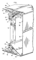
- a sign assembly has a rectangular frame 12 whose upper and lower frame members 14, 16 are shown in FIGURE 1 . It will be understood that the frame 12 will also have left and right hand side frame members (not shown). The various frame members are secured together at their ends by corner pieces (also not shown) to form a rectangular frame in a manner which will be readily apparent to a person skilled in the art.
- Each frame member is an aluminum extrusion.
- the frame members define an aperture 18 across which a sheet 20 of flexible sign material is stretched. Further description will be primarily in connection with upper frame 14 but it will be understood that such description also applies to the lower frame member 16 and the side frame members.
- the upper frame member 14 has an elongated body or base 22 from which upper and lower spaced walls 24, 26 extend at an angle of 45° to the vertical.
- the walls 24, 26 and base portion 22 form a U-shaped channel portion defining a channel 28 .
- the lower wall 26 extends beyond the upper wall 24 to form a lip member 30 which defines the edges of the aperture 18 .
- the sign sheet 20 has a main portion 32 extending across the aperture 18 and an end portion 34 which passes around the free end of the lip member 30 and into the channel 28 .
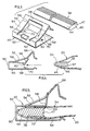
- the sheet end portion 34 is retained in the channel 28 by a tensioning or mounting bar 38 and a plurality of clips 40 .
- the sheet end portion 34 is folded over tensioning bar 38 and held thereon by the clips 40 which are spaced along the tensioning bar 38 .
- Each clip 40 is in turn retained within the channel 28 by engagement with one of a series of rearwardly facing shoulders 42 formed on the inner surface of the upper wall 28 .
- the tensioning bar 38 has a generally rectangular section, except that the rear end portion 44 is tapered. Forwardly of the tapered rear end portion 44 , the upper and lower surfaces of the tensioning bar 38 have closely spaced longitudinally extending ridges 46 which serve to grip the resilient material of sheet 20 .
- the tensioning bar 38 is also an aluminum extrusion.
- Each clip 40 is of resilient sheet metal and is formed by stamping and bending.
- the clip 40 is U-shaped with a base 50 and opposite sides or arms 52 , 54 .
- the medial portion of the side 52 is stamped out to form a tongue 56 which initially is inclined inwardly from the base 50 towards the opposite side 54 .
- the free end portion 58 is bent to extend in an outwardly inclined direction and is provided with a pair of inwardly and rearwardly extending prongs 60 at the line of bending.
- a portion of the tongue 56 and base 50 is removed to leave an aperture 62 , thereby permitting the tongue 56 to flex more easily relative to the base 50 .
- the remaining portion of the side 52 extends around the tongue 56 and comprises arms 64, 66 which extend from the base 50 and a free end portion 68 extending transversely between the outer ends of the arms 64, 66 .
- the arms 64, 66 After initially extending parallel to the opposite side 54 , the arms 64, 66 extend in an outwardly inclined direction to the free end portion 68 which is shaped to provide an outwardly projecting shoulder.
- the opposite side 54 of the clip 40 has a pair of prongs 70 stamped out therefrom, the prongs 70 being directed inwardly and rearwardly.
- bracing bars 72 are transversely spaced bracing bars 72 .
- Each bracing bar 72 is a tubular member whose upper end engages the underside of a flange 74 of the frame member 14 which extends rearwardly from the upper wall 24 of the channel 28 .
- the lower end of bracing bar 72 engages the upper surface of a similar part 76 of the frame member 16 .
- Each bracing bar 72 is secured to the base 22 of the frame member 14 by a bolt 76 which passes through bracing bar 72 into a longitudinally extending groove 78 in the base 22 of the frame member 14 .
- the groove 78 has longitudinally extending ridges 80 in opposed walls to engage the threads of the screws 76 .
- the bracing bar 72 is also secured to the lower frame member 16 in a similar manner (not shown).
- the sheet end portion 34 is wrapped around the tensioning bar 38 of each sheet holding assembly 36 in turn.
- the clips 40 are then pushed onto the tensioning bar 38 at longitudinally spaced intervals, see FIGURES 4 to 6 , until the tapered end 44 of the tensioning bar 38 engages the base 50 of each clip 40 (with the sign sheet end portion 34 therebetween).
- the prongs 60 on the tongue 76 and the prong 70 on the lower side 54 of each clip snap over and engage front end 47 of the tensioning bar 38 , thereby retaining the clips 40 and also the sign sheet portion 34 in engagement with tensioning bar 38 .
- the tensioning bar 38 with assembled sign end portion 34 and clips 40 is then inserted into a channel 28 of the frame member 14 or 16 as the case may be, see FIGURE 7 , until the sign sheet 20 is suitably tensioned.
- the outward projection 68 on the upper wall of each clip 40 snaps past each shoulder 42 in the channel 28 in turn more so that each clip 40 is retained in position by the shoulder 42 then engaged by the clip 40 .
- the tensioning bars 38 will be inserted an initial distance into the channels 28 in the upper and lower frame members 14, 16 until the sign sheet 20 is almost taut. The tensioning bars 38 are then pushed further into the channels 28 in turn until the desired tension in the sign sheet 20 is achieved. Similar comments apply of course to the side frame members.
- a cover plate 84 is fitted to the exterior of each frame member. As shown in FIGURE 2 , the cover plate 84 is secured to frame member 14 by screws 86 spaced therealong. The cover plate 84 covers the top of the frame member 14 so as to conceal the channel 28 and sheet end portions 34 . The cover plate 84 also extends rearwardly across the rearward extension 74 of the frame member 14 . A cover plate 84 is similarly secured to each of the various frame members.
- the channels 28 are positioned within the periphery of and behind the main portion 32 of the sign sheet 20 so that the frame is hidden behind the sign sheet main portion 32 when the sign assembly is viewed from the front.
- the cover plates 84 cover the frame members from other angles of view, thereby providing the sign assembly with an attractive appearance (as is also the case in U.S. patent 4,542,605 previously referred to).
- the length of the upper and lower frame members 14, 16 may be about 20 feet, with the length of the side members being about 4 feet.
- the clips 40 may be spaced apart at intervals of about 6 to 8 inches on the tensioning bars 38 .
- two tensioning bars 38 each with a length of about 10 feet may be provided for each of the upper and lower frame members.
- the bracing bars 72 may be spaced apart by about 4 to 5 feet.
- each clip 40 can be removed from the channel 28 by disengaging the outward projection 68 therefrom with a suitable tool (such as a screw driver) from shoulder 42 , at the same time pulling the sheet end portion 34 out of the channel 28 .
- a suitable tool such as a screw driver
Landscapes
- Physics & Mathematics (AREA)
- General Physics & Mathematics (AREA)
- Engineering & Computer Science (AREA)
- Theoretical Computer Science (AREA)
- Illuminated Signs And Luminous Advertising (AREA)
- Road Signs Or Road Markings (AREA)
- Clamps And Clips (AREA)
Applications Claiming Priority (2)
| Application Number | Priority Date | Filing Date | Title |
|---|---|---|---|
| US07/321,044 US4937961A (en) | 1989-03-09 | 1989-03-09 | Sign assembly |
| US321044 | 1999-05-27 |
Publications (2)
| Publication Number | Publication Date |
|---|---|
| EP0387030A2 true EP0387030A2 (fr) | 1990-09-12 |
| EP0387030A3 EP0387030A3 (fr) | 1992-01-02 |
Family
ID=23248942
Family Applications (1)
| Application Number | Title | Priority Date | Filing Date |
|---|---|---|---|
| EP19900302426 Withdrawn EP0387030A3 (fr) | 1989-03-09 | 1990-03-07 | Assemblage d'une enseigne |
Country Status (5)
| Country | Link |
|---|---|
| US (1) | US4937961A (fr) |
| EP (1) | EP0387030A3 (fr) |
| JP (1) | JPH0664422B2 (fr) |
| AU (1) | AU5079790A (fr) |
| CA (1) | CA2011572C (fr) |
Cited By (3)
| Publication number | Priority date | Publication date | Assignee | Title |
|---|---|---|---|---|
| EP0519161A3 (en) * | 1991-04-16 | 1993-05-12 | Sint Spa | Modular framework for illuminated signs using flexible material |
| EP0585741A2 (fr) * | 1992-09-03 | 1994-03-09 | LICHT UND LEUCHTEN E. KUBALD GmbH | Dispositif pour fixer et maintenir en tension des structures de grande dimension |
| GB2354870A (en) * | 1999-10-22 | 2001-04-04 | Richard Gardiner | Posters |
Families Citing this family (34)
| Publication number | Priority date | Publication date | Assignee | Title |
|---|---|---|---|---|
| US4862615A (en) * | 1988-04-28 | 1989-09-05 | Marketing Displays, Inc. | Releasable anchoring and tensioning apparatus for billboard displays |
| AU637213B2 (en) * | 1990-03-20 | 1993-05-20 | Scs Promotion Company Limited | Mounting advertising material |
| JPH0617180Y2 (ja) * | 1990-06-19 | 1994-05-02 | 株式会社アートパネル・コンサルタント | 掲示器における掲示体の懸架装置 |
| JPH0485484U (fr) * | 1990-11-30 | 1992-07-24 | ||
| US5301447A (en) * | 1990-12-20 | 1994-04-12 | Lotter Hancil R | Tensioning of flexible sheet |
| US5408770A (en) * | 1991-01-10 | 1995-04-25 | Scs Promotion Company Limited | Sheet stretcher including sheet attachment holes and sheet connection means |
| US5467546A (en) * | 1991-04-23 | 1995-11-21 | Signcomp, Inc. | Tensioned fabric sign |
| US5226250A (en) * | 1991-05-10 | 1993-07-13 | Larry Ulmer | Portable, collapsible craftwork frame for tensioning textiles |
| US5245774A (en) * | 1991-07-16 | 1993-09-21 | Quality Manufacturing Incorporated | Tensioning system for flexible sign assembly |
| US5255459A (en) * | 1991-12-12 | 1993-10-26 | Normand Verret | Framing system for signs |
| US5398388A (en) * | 1993-05-07 | 1995-03-21 | Coleman; Kelly R. | Tensioning assembly for flexible sign faces and awnings |
| EP0801780A1 (fr) * | 1993-05-07 | 1997-10-22 | COLEMAN, Kelly R. | Structure de cadre avec profile en c, pour panneaux d'affichage |
| SE503745C2 (sv) * | 1994-08-29 | 1996-08-19 | Goeran Johansson | Skylt med spännanordning för dukyta |
| US5647155A (en) * | 1995-11-22 | 1997-07-15 | Marketing Displays, Inc. | Sheet tensioning system |
| FR2743439B1 (fr) * | 1996-01-04 | 1999-05-07 | Crystal Sarl | Enseigne |
| US6073376A (en) * | 1998-08-24 | 2000-06-13 | Verret; Normand | Edging for sign casing |
| KR100311645B1 (ko) * | 1999-12-24 | 2001-10-12 | 이홍천 | 간판 |
| US6637080B2 (en) * | 2001-07-09 | 2003-10-28 | Normand Verret | Reversible flex holder for flexible face sign |
| SE520215C2 (sv) * | 2001-10-04 | 2003-06-10 | Goeran Johansson | Dukskylt |
| FR2857296B1 (fr) * | 2003-07-09 | 2006-11-10 | Prismaflex Int | Dispositif apte a realiser la mise sous tension et le maintien d'une toile. |
| US20060186617A1 (en) | 2003-07-11 | 2006-08-24 | Ryan Farrelly | Personal transportation device for supporting a user's foot having multiple transportation attachments |
| US7165296B2 (en) * | 2005-05-02 | 2007-01-23 | Coleman Kelly R | Flexible material tri-wedge bar and clamp assembly for use with a tensioning device |
| JP4367420B2 (ja) | 2005-07-22 | 2009-11-18 | オンキヨー株式会社 | スイッチング電源回路 |
| US7797864B2 (en) * | 2007-03-30 | 2010-09-21 | Larson James D | Static frame retension device |
| JP4931743B2 (ja) * | 2007-09-07 | 2012-05-16 | カンボウプラス株式会社 | シートの展張装置 |
| US8240072B2 (en) * | 2010-02-08 | 2012-08-14 | Moss, Inc. | Groove-mount fabric display system with two-part frame |
| US8595966B2 (en) | 2010-10-12 | 2013-12-03 | Signcomp, Llc | Sign assembly |
| EP2638539B1 (fr) * | 2010-11-10 | 2017-06-21 | B. Baldursson Reklam | Dispositif sur un cadre de montage |
| CA2846355C (fr) | 2013-03-15 | 2016-10-04 | Signcomp, Llc | Ensemble enseigne |
| US9284770B2 (en) * | 2014-03-19 | 2016-03-15 | C.R. Laurence Co., Inc. | Adjustable screen tensioning system |
| US9633583B2 (en) * | 2015-06-25 | 2017-04-25 | Apco Graphics, Inc. | Low profile, self-aligning customizable sign and method of displaying customizable information |
| ES2648712B1 (es) * | 2016-07-04 | 2018-10-10 | Dyr Proyectistas, S.L. | Perfil para marcos de paneles decorativos y retro-iluminables |
| WO2023058006A1 (fr) * | 2021-10-10 | 2023-04-13 | Signcomp, Llc | Système d'encadrement pour enseignes en tissu |
| US20260049501A1 (en) * | 2024-08-19 | 2026-02-19 | Ball Fabrics, Inc. | Windscreen attachment device and associated methods |
Family Cites Families (9)
| Publication number | Priority date | Publication date | Assignee | Title |
|---|---|---|---|---|
| US3329195A (en) * | 1965-05-24 | 1967-07-04 | Kinkead Industries | Projection screen or the like |
| US3529653A (en) * | 1968-10-14 | 1970-09-22 | Edward C Fey Jr | Expandable frame for painting canvas |
| US3803671A (en) * | 1972-10-26 | 1974-04-16 | Stuppy Flora Inc | Attaching assembly for sheet material |
| US4265039A (en) * | 1979-08-23 | 1981-05-05 | Abc Extrusion Company | Display signs |
| US4327513A (en) * | 1980-01-21 | 1982-05-04 | Pana-Plex Company, Inc. | Illuminated outdoor sign and housing |
| US4452000A (en) * | 1981-06-30 | 1984-06-05 | Signtech Inc. | Illuminatable sign |
| JPS612689U (ja) * | 1984-06-08 | 1986-01-09 | 株式会社新村ハウジング | 掲示幕保持装置 |
| US4554754A (en) * | 1984-07-06 | 1985-11-26 | Johann Stilling | Sign with flexible face |
| CA1240149A (fr) * | 1985-04-25 | 1988-08-09 | Signtech Inc. | Enseigne publicitaire ou panneau avertisseur |
-
1989
- 1989-03-09 US US07/321,044 patent/US4937961A/en not_active Expired - Lifetime
-
1990
- 1990-03-06 AU AU50797/90A patent/AU5079790A/en not_active Abandoned
- 1990-03-06 CA CA002011572A patent/CA2011572C/fr not_active Expired - Lifetime
- 1990-03-07 EP EP19900302426 patent/EP0387030A3/fr not_active Withdrawn
- 1990-03-09 JP JP2056815A patent/JPH0664422B2/ja not_active Expired - Lifetime
Cited By (3)
| Publication number | Priority date | Publication date | Assignee | Title |
|---|---|---|---|---|
| EP0519161A3 (en) * | 1991-04-16 | 1993-05-12 | Sint Spa | Modular framework for illuminated signs using flexible material |
| EP0585741A2 (fr) * | 1992-09-03 | 1994-03-09 | LICHT UND LEUCHTEN E. KUBALD GmbH | Dispositif pour fixer et maintenir en tension des structures de grande dimension |
| GB2354870A (en) * | 1999-10-22 | 2001-04-04 | Richard Gardiner | Posters |
Also Published As
| Publication number | Publication date |
|---|---|
| JPH0664422B2 (ja) | 1994-08-22 |
| JPH0321984A (ja) | 1991-01-30 |
| US4937961A (en) | 1990-07-03 |
| CA2011572A1 (fr) | 1990-09-09 |
| CA2011572C (fr) | 1995-03-07 |
| EP0387030A3 (fr) | 1992-01-02 |
| AU5079790A (en) | 1990-10-11 |
Similar Documents
| Publication | Publication Date | Title |
|---|---|---|
| CA2011572C (fr) | Cadre pour enseigne | |
| US5033216A (en) | Sign assembly | |
| US5467546A (en) | Tensioned fabric sign | |
| CA1100116A (fr) | Traduction non-disponible | |
| US4216597A (en) | Picture frame retaining clip | |
| AU739508B2 (en) | Clip for mounting objects on a wall stud | |
| US3854269A (en) | Connecting means | |
| US4564165A (en) | Attaching device | |
| CA2128806C (fr) | Dispositif pour attacher les ressorts au bati d'un meuble | |
| CA1145271A (fr) | Materiau de guipage pour canalisations, cables et articles analogues | |
| US4362284A (en) | Fastener for attaching electrical boxes to steel studs | |
| GB2297905A (en) | Flexible hair clip | |
| US4514026A (en) | Plug locking device | |
| US4641441A (en) | Frame retaining clip | |
| US4066233A (en) | Securing device | |
| US6061941A (en) | Flex holder for flexible face sign | |
| CA1044345A (fr) | Rondelles de neutralisation des contraints | |
| EP0809454B1 (fr) | Cadre pour photo | |
| US3349443A (en) | Fastener clip for mounting pictures and the like | |
| AU739513B2 (en) | Adjustable two-piece clip for mounting objects on a wall stud | |
| US5063486A (en) | Mounting apparatus for a fluorescent lamp holder | |
| US5810305A (en) | Mounting device for securing an object to a post | |
| EP0599634B1 (fr) | Dispositif de couplage pour composants de support de câble | |
| EP0287723B1 (fr) | Cadre pour images | |
| GB2229846A (en) | Sign |
Legal Events
| Date | Code | Title | Description |
|---|---|---|---|
| PUAI | Public reference made under article 153(3) epc to a published international application that has entered the european phase |
Free format text: ORIGINAL CODE: 0009012 |
|
| AK | Designated contracting states |
Kind code of ref document: A2 Designated state(s): AT BE CH DE DK ES FR GB GR IT LI LU NL SE |
|
| PUAL | Search report despatched |
Free format text: ORIGINAL CODE: 0009013 |
|
| AK | Designated contracting states |
Kind code of ref document: A3 Designated state(s): AT BE CH DE DK ES FR GB GR IT LI LU NL SE |
|
| STAA | Information on the status of an ep patent application or granted ep patent |
Free format text: STATUS: THE APPLICATION IS DEEMED TO BE WITHDRAWN |
|
| 18D | Application deemed to be withdrawn |
Effective date: 19920703 |