EP0387076A2 - Offshore-Ölproduktionssystem - Google Patents
Offshore-Ölproduktionssystem Download PDFInfo
- Publication number
- EP0387076A2 EP0387076A2 EP90302514A EP90302514A EP0387076A2 EP 0387076 A2 EP0387076 A2 EP 0387076A2 EP 90302514 A EP90302514 A EP 90302514A EP 90302514 A EP90302514 A EP 90302514A EP 0387076 A2 EP0387076 A2 EP 0387076A2
- Authority
- EP
- European Patent Office
- Prior art keywords
- riser
- subsea
- buoy
- offshore oil
- oil production
- Prior art date
- Legal status (The legal status is an assumption and is not a legal conclusion. Google has not performed a legal analysis and makes no representation as to the accuracy of the status listed.)
- Granted
Links
Images


Classifications
-
- B—PERFORMING OPERATIONS; TRANSPORTING
- B63—SHIPS OR OTHER WATERBORNE VESSELS; RELATED EQUIPMENT
- B63B—SHIPS OR OTHER WATERBORNE VESSELS; EQUIPMENT FOR SHIPPING
- B63B22/00—Buoys
- B63B22/02—Buoys specially adapted for mooring a vessel
- B63B22/021—Buoys specially adapted for mooring a vessel and for transferring fluids, e.g. liquids
- B63B22/023—Buoys specially adapted for mooring a vessel and for transferring fluids, e.g. liquids submerged when not in use
-
- E—FIXED CONSTRUCTIONS
- E21—EARTH OR ROCK DRILLING; MINING
- E21B—EARTH OR ROCK DRILLING; OBTAINING OIL, GAS, WATER, SOLUBLE OR MELTABLE MATERIALS OR A SLURRY OF MINERALS FROM WELLS
- E21B43/00—Methods or apparatus for obtaining oil, gas, water, soluble or meltable materials or a slurry of minerals from wells
- E21B43/01—Methods or apparatus for obtaining oil, gas, water, soluble or meltable materials or a slurry of minerals from wells specially adapted for obtaining from underwater installations
Definitions
- This invention relates to an offshore oil production and mooring system, particularly a system for developing small fields.
- U.K. Patent Application No. 2,066,758B discloses and claims an oil production system suitable for use at an offshore location comprising a floating storage vessel to receive the produced oil and having means for dynamic positioning, a single detachable riser supported from the vessel and detachably connectable to a subsea well head or to the vessel, the vessel further having means for separating the oil and its associated gas and employing the latter as fuel to power the dynamic positioning means.
- the system is designed to produce oil from a single subsea well head.
- FRAMS flexible riser and mooring system
- an offshore oil production and mooring system comprising:-
- a water injection (i) line may also be connected to the subsea connector (b) and supported by the lower support line (e), the subsea restraining buoy (c) and the upper support line (f) and connected to the riser endpiece (d).
- the riser endpiece preferably comprises a male connector and a buoyancy module.
- the buoyancy module preferably comprises an asymmetrically fitted portion to prevent misalignment on connection.
- the riser endpiece is preferably fitted with a cover to protect the connector and guide the riser endpiece when a connection is being made.
- the cover is suitably in the shape of a sledge.
- the riser endpiece When the system is "parked", ie, when it is not connected to the loading vessel, the riser endpiece is anchored with the position of the anchor indicated at the sea surface by a pennant buoy. Restraining the riser endpiece prevents the riser and lines from drifting back and twisting.
- the riser endpiece is lifted and the connector of the riser endpiece connected to a corresponding connector on board the vessel.
- the vessel is adapted to receive, store, transport and preferably degas produced crude oil.
- a suitable size for the tanker is in the range 40,000-70,000 dwt.
- the vessel When moored to the flexible riser and mooring system, the vessel is free to rotate around the mooring system using the torsional flexibility of the lower support line, the riser, the umbilical and the water injection line, if present. There are no swivels in the system, thus reducing complexity and costs.
- Cables of wire rope are very suitable materials for the lower and upper support lines.
- the lower support line is preferably connected to the subsea base by means of a universal joint.
- the production riser, the umbilical and the water injection line are preferably not amalgamated into a bundle but are positioned along the support lines by spiders.
- the lower riser ie that part of the riser below the restraining buoy, is designed to accept all the torsion input by rotation of the vessel as it moves around the mooring, up to the design torsion limit.
- the lower riser may be designed with the flexibles having an excess length over the lower support line of say 5 to 15%, preferably about 10%.
- This arrangement allows out of plane bending to occur as well as twisting and prevents the end fitting having to restrain excessive torque.
- the spiders should be positioned at regular intervals, eg 5m.
- the lower riser spiders are preferably held in position by separation cables, preferably two in number, suspended from the restraining buoy.
- the torsional limit of flexible pipe is normally limited to ⁇ 1 degree per metre. With the above arrangement it is possible for the rotation limit to be increased to ⁇ 3 degrees per metre.
- the upper riser spiders are similar to those used on the lower riser. Separation cables are not required, however, because the rotational movement is transferred to the lower riser.
- the subsea restraining buoy may be spherical or cylindrical in configuration, but preferably the latter. It behaves as an inverted pendulum and therefore the greater the horizontal displacement, the greater is the restoring force.
- a convenient size for the restraining buoy is 200 displacement tonnes.
- Suitable materials of construction for the restraining buoy include steel and GRP.
- the lower support line should be as long as possible. A long length will reduce the increase in restoring force due to the change of vessel offset during passing of a wave. Vessels moored on a longer length of mooring have higher operational limits than with shorter lengths. The longer length reduces the possibility of snatch loads and increases fatigue life of the mooring.
- the upper support line should be at least as long as the lower support line to allow for limited movement of the vessel (e.g. ⁇ 5% water depth) without the exertion of undue forces.
- the restraining buoy is preferably moored at a depth in the range 1/2 to 1/3 water depth below the sea surface, e.g. 50m, to ensure clearance by other vessels.
- the mooring buoy may be of a conventional type.
- the vessel is preferably provided with processing faciities to degas the crude oil before storage and subsequent transportation. Gas is separated from the well stream fluids and excess gas flared.
- the tanker loadable crude is pumped into the tanker cargo holds. When the tanks are full, the tanker disconnects the mooring, shuts down the reservoir and sails to an unloading terminal.
- the topsides equipment should be selected and sized in accordance with the following main principles: - Minimum oil processing, consistent with stabilisation and high recovery of crude oil. - Power generation installed sufficient to meet power requirements when on station, to take advantage of available gas, rather than use vessel's power. - Flaring of produced gas surplus to fuel requirement. - Injection water required for reservoir pressure maintenance filtered and de-oxygenated to a reasonable degree only, taking account of anticipated high permeability and short field life. - Maximum use made of existing tanker facilities: accommodation, fresh water supply, power generation and sea water pumping. - Produced water treatment on the tanker.
- the subsea elements of the development may comprise, for example: - Two producer and two water injection wells in a tight cluster around a manifold structure to which they are connected by flexible jumper hoses.
- the manifold structure comprising a space frame supporting a production header, an injection water header, a service header, control pod and distribution pipework for chemical injection and control fluids.
- Valve Control System Power supply and control room are on board the vessel, composite electro-hydraulic umbilical from the vessel to the manifold subsea control pod and jumper hoses and power cables to individual wells.
- Suitable reservoirs would have a peak throughput of about 8-10,0000 bpd and a field life of about five years.
- the flexible riser and mooring system comprises a subsea restraining buoy (1) moored by means of a flexible lower support line (2) to a subsea base (3) located on the sea bed.
- the production riser (4), water injection line (5) and umbilical (6) terminate in connectors in a subsea connector (7) which in turn is connected to a subsea production system (not shown).
- the subsea restraining buoy (1) is also connected to a buoyant riser endpiece (8) by means of a flexible upper support line (9).
- the flexible production riser (4), water injection line (5) and umbilical (6) pass over the restraining buoy (1) and continue in association with the upper support line and also terminate in the riser endpiece (8).
- the riser endpiece (8) is anchored subsea by means of a mooring chafe chain (34) attached to a polyester braidline pick-up line (10) attached to an anchor (11).
- the position of the anchor (11) is marked by a mooring pick-up buoy (12).
- the position of the restraining buoy (1), and hence of the producing field is marked by a field marker buoy (13) tethered to a small subsea buoy (14) tethered to the restraining buoy (1).
- the subsea restraining buoy (1) is moored 100m above the sea bed in a total water depth of 150m, i.e, the lower support line (2) is 100m long.
- the upper support line (9) mooring the tanker (15) to the buoy (1) is 150m long.
- the tanker (15) is fitted with a cleft bow (16) shown more clearly in Figure 9, a flare stack (17), process equipment (18) and storage tanks (19).
- Figure 3 is a section on AA of Figure 2 showing a detail of the connection of the lower support line (2) to the subsea base (3).
- the support line (2) is a 5 inch spiral wire rope connected to an open socket connector (20) in turn connected by a universal joint (21) to the subsea base (3).
- the universal joint (21) has water lubricated bearings.
- Figure 4 is a section on BB of Figure 2, i.e. at the mid point of the lower support line.
- the support line (9) is also a 5 inch spiral strand wire rope.
- the production riser (4) and the water injection line (5) are 4 inch O/D flexible tubes and the umbilical (6) is a 5 inch O/D line.
- the lines are linked together by means of spiders (22) repeated at regular intervals along the lines as indicated in Figure 1.
- the configuration shown in Figure 4 maximises strength and resistance to twisting by positioning the support line at the centre of an equilateral triangle.
- Figure 5 shows the configuration adopted when the group of lines approaches a surface to which the support lines are connected and this case, the spiders (23) are of different shape and the support line is at the apex of an isosceles triangle with the other lines and umbilical forming the base. This configuration facilitates junctions and connections, as indicated in Figure 1.
- the spiders (22) and (23) are supported on separation cables (24) and (25) in a manner similar to the rungs of a rope ladder, the cables (24) and (25) being suspended from the restraining buoy (1).
- FIGs 6 and 7 relate to the restraining buoy (1).
- the buoy is a spherical 8m diameter steel structure of 200 tonnes. It is divided into compartments by stiffened plate bulkheads (26). These bulkheads are aligned to carry the loads from the lower and upper support lines (2) and (9). The lines are attached to the buoy by open fork pinned sockets (27) and (28). The buoy is also strengthened by ring stiffeners (29).
- Figure 7 is a section on DD of Figure 6 showing how the production riser (4), water injection line (5) and umbilical (6) are carried over the surface of the buoy (1).
- An internal bulkhead (26) and an internal ring stiffener (29) are also illustrated.
- the riser endpiece (8) comprises three major elements, viz a cover in the form of a guide sledge (30), the male half (31) of a coupling having guide pins (42) and a buoyancy module (32).
- the female half (41) of the coupling forms part of the entry system in the cleft bow (16) of the tanker (15).
- the guide sledge (30) is an open fabricated steel structure, sledge shaped to allow a smooth pull in at the bow of the tanker whilst offering protection to the male half of the coupling and also to the female half when engaged.
- the sledge has built in alignment guides to assist the coupling to engage.
- 10% eccentricity is added to the buoyancy module (32) which is basically cuboid with a hole down its longitudinal centre line to allow the passage of flexibles, ie the production riser (4), the water injection line (5) and the umbilical (6) from the coupling.
- the eccentricity is added in the form of a blister (33) attached to one side of the buoyancy module (32) to ensure that the riser endpiece always rotates clockwise on emergence from the sea and anti-clockwise on re-entry.
- the upper support line (9) and a mooring chain (34) attached to the pick-up line (10) are also connected to the buoyancy module (32).
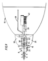
- Figure 9 is a plan view of the bow of the tanker showing the cleft 16 protected by flared extension sides (35).
- Vertical guide plates 36 are provided which co-operate with the guide sledge (30) of Figure 8 to guide the riser endpiece (8) into the correct location for coupling its male half with the female half (41) associated with a termination box (37) on board the tanker.
- Production fluid is taken from the termination box (37) to the processing equipment by means of a pipeline (38).
- the coupling unit is a relatively standard MIB latching unit conveying the contents of well fluid, well injection water and electric and hydraulic lines.
- the anchor chain (34) and pick up line (10) are pulled through a chain stopper unit (39) by means of a traction winch (40).
- the stopper unit (39) comprises a fairlead and chain stopper assembly including a hydraulically activated cradle-mounted latch and a load cell.
- the traction winch (40) is a cantilevered type horizontal twin drum winch.
- the riser endpiece is drawn out of the water by the cable being winched in on the traction winch.
- the endpiece is aligned by the guides.
- the hawser stopper unit clamps onto the chain.
- the female connector half is lowered onto the endpiece by a hoist and the connection made up.
- a typical mooring sequence is outlined below:-
- the FRAMS tanker hauls in the messenger rope and the pick-up rope, and feeds these to a storage drum, via the traction winch.
- a normal unmooring sequence is as follows:-
Landscapes
- Engineering & Computer Science (AREA)
- Geology (AREA)
- Life Sciences & Earth Sciences (AREA)
- Mining & Mineral Resources (AREA)
- Environmental & Geological Engineering (AREA)
- Fluid Mechanics (AREA)
- Physics & Mathematics (AREA)
- General Life Sciences & Earth Sciences (AREA)
- Geochemistry & Mineralogy (AREA)
- Chemical & Material Sciences (AREA)
- Combustion & Propulsion (AREA)
- Mechanical Engineering (AREA)
- Ocean & Marine Engineering (AREA)
- Earth Drilling (AREA)
Applications Claiming Priority (2)
| Application Number | Priority Date | Filing Date | Title |
|---|---|---|---|
| GB8905364 | 1989-03-09 | ||
| GB898905364A GB8905364D0 (en) | 1989-03-09 | 1989-03-09 | Offshore oil production system |
Publications (3)
| Publication Number | Publication Date |
|---|---|
| EP0387076A2 true EP0387076A2 (de) | 1990-09-12 |
| EP0387076A3 EP0387076A3 (de) | 1991-10-30 |
| EP0387076B1 EP0387076B1 (de) | 1996-06-05 |
Family
ID=10652996
Family Applications (1)
| Application Number | Title | Priority Date | Filing Date |
|---|---|---|---|
| EP90302514A Expired - Lifetime EP0387076B1 (de) | 1989-03-09 | 1990-03-08 | Offshore-Ölproduktionssystem |
Country Status (6)
| Country | Link |
|---|---|
| US (1) | US5007482A (de) |
| EP (1) | EP0387076B1 (de) |
| CA (1) | CA2011835A1 (de) |
| DE (1) | DE69027237D1 (de) |
| GB (1) | GB8905364D0 (de) |
| NO (1) | NO307598B1 (de) |
Cited By (6)
| Publication number | Priority date | Publication date | Assignee | Title |
|---|---|---|---|---|
| WO1998036153A1 (en) * | 1997-02-13 | 1998-08-20 | Hitec Asa | Support of a number of parallel pipelines/hoses/cables etc. between a surface vessel and a point on the seabed |
| WO2006006852A1 (en) * | 2004-07-12 | 2006-01-19 | Heerema Marine Contractors Nederland B.V. | Method and device for connecting a riser to a target structure |
| KR100819613B1 (ko) * | 2003-09-19 | 2008-04-07 | 가부시키가이샤 닛폰 쇼쿠바이 | 수분 흡수제와 그 제조방법 |
| EP2003285A1 (de) * | 2007-06-15 | 2008-12-17 | Vetco Gray Controls Limited | System zum Entfalten von Versorgungskabeln |
| WO2013097007A1 (pt) * | 2011-12-29 | 2013-07-04 | Petróleo Brasileiro S.A - Petrobras | Luva de amortecimento e método de ancoragem |
| WO2017151297A1 (en) * | 2016-03-02 | 2017-09-08 | Cameron Solutions, Inc. | Subsea deoxygenation in a water injection process plant |
Families Citing this family (21)
| Publication number | Priority date | Publication date | Assignee | Title |
|---|---|---|---|---|
| GB9626021D0 (en) * | 1996-12-14 | 1997-01-29 | Head Philip F | A riser system for a sub sea well and method of operation |
| US5887659A (en) * | 1997-05-14 | 1999-03-30 | Dril-Quip, Inc. | Riser for use in drilling or completing a subsea well |
| FR2768457B1 (fr) * | 1997-09-12 | 2000-05-05 | Stolt Comex Seaway | Dispositif de transport sous-marin de produits petroliers a colonne montante |
| FR2780442B1 (fr) * | 1998-06-30 | 2000-07-28 | Inst Francais Du Petrole | Systeme de production polyphasique adapte pour les grandes profondeurs d'eau |
| FR2787859B1 (fr) * | 1998-12-23 | 2001-01-26 | Inst Francais Du Petrole | Riser ou colonne hybride pour le transfert de fluide |
| US6386290B1 (en) | 1999-01-19 | 2002-05-14 | Colin Stuart Headworth | System for accessing oil wells with compliant guide and coiled tubing |
| US6244347B1 (en) | 1999-07-29 | 2001-06-12 | Dril-Quip, Inc. | Subsea well drilling and/or completion apparatus |
| US6453838B1 (en) | 2000-10-20 | 2002-09-24 | Ocean Production Technology, Llc | Turret-less floating production ship |
| US6688348B2 (en) * | 2001-11-06 | 2004-02-10 | Fmc Technologies, Inc. | Submerged flowline termination buoy with direct connection to shuttle tanker |
| US7434624B2 (en) * | 2002-10-03 | 2008-10-14 | Exxonmobil Upstream Research Company | Hybrid tension-leg riser |
| US6780072B1 (en) * | 2003-02-14 | 2004-08-24 | Petroleo Brasileiro S.A.-Petrobras | Subsurface buoy and methods of installing, tying and dynamically stabilizing the same |
| EP1603796B1 (de) | 2003-03-06 | 2011-05-04 | Petróleo Brasileiro S.A. Petrobras | Unterwasserboje und verfahren zu deren installation, befestigung und dynamischer stabilisierung |
| GB0409361D0 (en) * | 2004-04-27 | 2004-06-02 | Stolt Offshore Sa | Marine riser tower |
| EP2291577A1 (de) * | 2008-04-09 | 2011-03-09 | Amog Pty Ltd | Steigrohrstütze |
| GB2474211B (en) * | 2008-08-13 | 2012-05-02 | Schlumberger Holdings | Umbilical management system and method for subsea well intervention |
| BRPI0805633A2 (pt) * | 2008-12-29 | 2010-09-14 | Petroleo Brasileiro Sa | sistema de riser hìbrido auto-sustentado aperfeiçoado e método de instalação |
| WO2011008593A1 (en) * | 2009-07-15 | 2011-01-20 | Shell Oil Company | Mid-water transfer line |
| WO2011150363A1 (en) * | 2010-05-28 | 2011-12-01 | Weatherford/Lamb, Inc. | Deepwater completion installation and intervention system |
| CN104203742B (zh) * | 2012-03-14 | 2016-11-09 | 国际壳牌研究有限公司 | 用于系泊生产平台的系统和方法以及用于保护生产立管和浮式生产平台免遭风暴影响的方法 |
| CN102852494B (zh) * | 2012-08-28 | 2015-03-18 | 中国石油化工股份有限公司 | 海洋采油平台注聚采油移动式干粉储料分散模块 |
| DE102019110506A1 (de) * | 2019-04-23 | 2020-10-29 | Innogy Se | Gründung eines Offshore-Bauwerks mit einem Übertragungskabel und einem Schutzelement |
Family Cites Families (13)
| Publication number | Priority date | Publication date | Assignee | Title |
|---|---|---|---|---|
| GB1177926A (en) * | 1966-05-06 | 1970-01-14 | Shell Int Research | One Point Mooring System for Loading Fluids into or Unloading Fluids from a Ship |
| FR2370219A2 (fr) * | 1976-11-09 | 1978-06-02 | Coflexip | Dispositif de canalisations pour la collecte des hydrocarbures produits par des puits situes en eaux profondes |
| US4182584A (en) * | 1978-07-10 | 1980-01-08 | Mobil Oil Corporation | Marine production riser system and method of installing same |
| US4650431A (en) * | 1979-03-28 | 1987-03-17 | Amtel, Inc | Quick disconnect storage production terminal |
| US4423984A (en) * | 1980-12-29 | 1984-01-03 | Mobil Oil Corporation | Marine compliant riser system |
| FR2507672A1 (fr) * | 1981-06-12 | 1982-12-17 | Inst Francais Du Petrole | Colonne montante pour les grandes profondeurs d'eau |
| US4470722A (en) * | 1981-12-31 | 1984-09-11 | Exxon Production Research Co. | Marine production riser system and method of installing same |
| US4478586A (en) * | 1982-06-22 | 1984-10-23 | Mobil Oil Corporation | Buoyed moonpool plug for disconnecting a flexible flowline from a process vessel |
| US4637335A (en) * | 1982-11-01 | 1987-01-20 | Amtel, Inc. | Offshore hydrocarbon production system |
| US4529334A (en) * | 1984-01-30 | 1985-07-16 | Exxon Production Research Co. | Production riser assembly |
| US4645467A (en) * | 1984-04-24 | 1987-02-24 | Amtel, Inc. | Detachable mooring and cargo transfer system |
| US4604961A (en) * | 1984-06-11 | 1986-08-12 | Exxon Production Research Co. | Vessel mooring system |
| NO160914C (no) * | 1986-03-24 | 1989-06-14 | Svensen Niels Alf | Boeyelastningssystem for offshore petroleumsproduksjon. |
-
1989
- 1989-03-09 GB GB898905364A patent/GB8905364D0/en active Pending
-
1990
- 1990-03-08 DE DE69027237T patent/DE69027237D1/de not_active Expired - Lifetime
- 1990-03-08 EP EP90302514A patent/EP0387076B1/de not_active Expired - Lifetime
- 1990-03-09 US US07/490,879 patent/US5007482A/en not_active Expired - Fee Related
- 1990-03-09 NO NO901109A patent/NO307598B1/no unknown
- 1990-03-09 CA CA002011835A patent/CA2011835A1/en not_active Abandoned
Cited By (8)
| Publication number | Priority date | Publication date | Assignee | Title |
|---|---|---|---|---|
| WO1998036153A1 (en) * | 1997-02-13 | 1998-08-20 | Hitec Asa | Support of a number of parallel pipelines/hoses/cables etc. between a surface vessel and a point on the seabed |
| KR100819613B1 (ko) * | 2003-09-19 | 2008-04-07 | 가부시키가이샤 닛폰 쇼쿠바이 | 수분 흡수제와 그 제조방법 |
| WO2006006852A1 (en) * | 2004-07-12 | 2006-01-19 | Heerema Marine Contractors Nederland B.V. | Method and device for connecting a riser to a target structure |
| EP2003285A1 (de) * | 2007-06-15 | 2008-12-17 | Vetco Gray Controls Limited | System zum Entfalten von Versorgungskabeln |
| US8096364B2 (en) | 2007-06-15 | 2012-01-17 | Vetco Gray Controls Limited | Umbilical deployment system |
| WO2013097007A1 (pt) * | 2011-12-29 | 2013-07-04 | Petróleo Brasileiro S.A - Petrobras | Luva de amortecimento e método de ancoragem |
| WO2017151297A1 (en) * | 2016-03-02 | 2017-09-08 | Cameron Solutions, Inc. | Subsea deoxygenation in a water injection process plant |
| US10370272B2 (en) | 2016-03-02 | 2019-08-06 | Cameron Solutions, Inc. | Subsea deoxygenation in a water injection process plant |
Also Published As
| Publication number | Publication date |
|---|---|
| US5007482A (en) | 1991-04-16 |
| EP0387076A3 (de) | 1991-10-30 |
| NO901109D0 (no) | 1990-03-09 |
| CA2011835A1 (en) | 1990-09-09 |
| EP0387076B1 (de) | 1996-06-05 |
| NO307598B1 (no) | 2000-05-02 |
| DE69027237D1 (de) | 1996-07-11 |
| GB8905364D0 (en) | 1989-04-19 |
| NO901109L (no) | 1990-09-10 |
Similar Documents
| Publication | Publication Date | Title |
|---|---|---|
| US5007482A (en) | Offshore oil production system | |
| CN101035708B (zh) | 近海船舶系泊和升降器入舱系统 | |
| CA1195585A (en) | Moonpool plug for connecting a flexible flowline to a process vessel | |
| CN102264596B (zh) | 用于海上输送碳氢化合物的多功能单元 | |
| US6688930B2 (en) | Hybrid buoyant riser/tension mooring system | |
| RU2144611C1 (ru) | Судно для добычи или транспортировки углеводородов с морских месторождений и способ налива нефти по погрузочному рукаву | |
| CA1196232A (en) | Offshore process vessel and a method of operating same to receive oil and/or gas production from a subsea well | |
| US5275510A (en) | Offshore tanker loading system | |
| US6851994B2 (en) | Disconnectable mooring system and LNG transfer system and method | |
| CN103874627B (zh) | 一种用于船舶锚泊系统的连接器组件 | |
| WO1998007616A1 (en) | Vessel turret systems | |
| US7997947B2 (en) | Deep water hydrocarbon transfer system | |
| US6932127B2 (en) | System for transferring oil from an offshore platform to a tanker | |
| CN109415107B (zh) | 可断开的船首转塔 | |
| GB2459739A (en) | A counterbalanced cantilever connector assembly for a vessel | |
| Mace et al. | Disconnectable riser turret mooring system for Jabiru's tanker-based floating production system | |
| Rutkowski et al. | Comparison of the Operational Performance of Different Cargo Offshore Loading Systems, in Particular the Bow Loading System (BLS), the Stern Discharge System (SDS), Submerged Turret Loading (STL) and the Conventional Midship Cargo Manifold (MCM) used on Flex Shuttle Tanker | |
| AU2005203655A1 (en) | System for managing offshore drilled products |
Legal Events
| Date | Code | Title | Description |
|---|---|---|---|
| PUAI | Public reference made under article 153(3) epc to a published international application that has entered the european phase |
Free format text: ORIGINAL CODE: 0009012 |
|
| AK | Designated contracting states |
Kind code of ref document: A2 Designated state(s): DE ES FR GB IT NL SE |
|
| PUAL | Search report despatched |
Free format text: ORIGINAL CODE: 0009013 |
|
| AK | Designated contracting states |
Kind code of ref document: A3 Designated state(s): DE ES FR GB IT NL SE |
|
| 17P | Request for examination filed |
Effective date: 19920410 |
|
| 17Q | First examination report despatched |
Effective date: 19930723 |
|
| GRAA | (expected) grant |
Free format text: ORIGINAL CODE: 0009210 |
|
| ITPR | It: changes in ownership of a european patent |
Owner name: C.NE EPO REG. 20;GEC ALSTHOM ENGINEERING SYSTEMS L |
|
| AK | Designated contracting states |
Kind code of ref document: B1 Designated state(s): DE ES FR GB IT NL SE |
|
| PG25 | Lapsed in a contracting state [announced via postgrant information from national office to epo] |
Ref country code: FR Effective date: 19960605 Ref country code: ES Free format text: THE PATENT HAS BEEN ANNULLED BY A DECISION OF A NATIONAL AUTHORITY Effective date: 19960605 |
|
| REF | Corresponds to: |
Ref document number: 69027237 Country of ref document: DE Date of ref document: 19960711 |
|
| RAP2 | Party data changed (patent owner data changed or rights of a patent transferred) |
Owner name: GEC ALSTHOM ENGINEERING SYSTEMS LIMITED |
|
| ITF | It: translation for a ep patent filed | ||
| PG25 | Lapsed in a contracting state [announced via postgrant information from national office to epo] |
Ref country code: SE Effective date: 19960905 |
|
| PG25 | Lapsed in a contracting state [announced via postgrant information from national office to epo] |
Ref country code: DE Effective date: 19960906 |
|
| NLT2 | Nl: modifications (of names), taken from the european patent patent bulletin |
Owner name: GEC ALSTHOM ENGINEERING SYSTEMS LIMITED |
|
| NLXE | Nl: other communications concerning ep-patents (part 3 heading xe) |
Free format text: PAT.BUL.08/96 PAGE 1086:CORR.:GEC ALSTHOM ENGINEERING SYSTEMS LIMITED |
|
| EN | Fr: translation not filed | ||
| PLBE | No opposition filed within time limit |
Free format text: ORIGINAL CODE: 0009261 |
|
| STAA | Information on the status of an ep patent application or granted ep patent |
Free format text: STATUS: NO OPPOSITION FILED WITHIN TIME LIMIT |
|
| 26N | No opposition filed | ||
| PGFP | Annual fee paid to national office [announced via postgrant information from national office to epo] |
Ref country code: GB Payment date: 20000308 Year of fee payment: 11 |
|
| PGFP | Annual fee paid to national office [announced via postgrant information from national office to epo] |
Ref country code: NL Payment date: 20000330 Year of fee payment: 11 |
|
| PG25 | Lapsed in a contracting state [announced via postgrant information from national office to epo] |
Ref country code: GB Free format text: LAPSE BECAUSE OF NON-PAYMENT OF DUE FEES Effective date: 20010308 |
|
| PG25 | Lapsed in a contracting state [announced via postgrant information from national office to epo] |
Ref country code: NL Free format text: LAPSE BECAUSE OF NON-PAYMENT OF DUE FEES Effective date: 20011001 |
|
| GBPC | Gb: european patent ceased through non-payment of renewal fee |
Effective date: 20010308 |
|
| NLV4 | Nl: lapsed or anulled due to non-payment of the annual fee |
Effective date: 20011001 |
|
| PG25 | Lapsed in a contracting state [announced via postgrant information from national office to epo] |
Ref country code: IT Free format text: LAPSE BECAUSE OF NON-PAYMENT OF DUE FEES;WARNING: LAPSES OF ITALIAN PATENTS WITH EFFECTIVE DATE BEFORE 2007 MAY HAVE OCCURRED AT ANY TIME BEFORE 2007. THE CORRECT EFFECTIVE DATE MAY BE DIFFERENT FROM THE ONE RECORDED. Effective date: 20050308 |