EP0387412A2 - Procédé et dispositif pour revêtir une bande en particulier une bande de papier ou de carton - Google Patents
Procédé et dispositif pour revêtir une bande en particulier une bande de papier ou de carton Download PDFInfo
- Publication number
- EP0387412A2 EP0387412A2 EP89122877A EP89122877A EP0387412A2 EP 0387412 A2 EP0387412 A2 EP 0387412A2 EP 89122877 A EP89122877 A EP 89122877A EP 89122877 A EP89122877 A EP 89122877A EP 0387412 A2 EP0387412 A2 EP 0387412A2
- Authority
- EP
- European Patent Office
- Prior art keywords
- coating
- heating
- weight distribution
- metering element
- working width
- Prior art date
- Legal status (The legal status is an assumption and is not a legal conclusion. Google has not performed a legal analysis and makes no representation as to the accuracy of the status listed.)
- Granted
Links
Images

Classifications
-
- B—PERFORMING OPERATIONS; TRANSPORTING
- B05—SPRAYING OR ATOMISING IN GENERAL; APPLYING FLUENT MATERIALS TO SURFACES, IN GENERAL
- B05C—APPARATUS FOR APPLYING FLUENT MATERIALS TO SURFACES, IN GENERAL
- B05C11/00—Component parts, details or accessories not specifically provided for in groups B05C1/00 - B05C9/00
- B05C11/02—Apparatus for spreading or distributing liquids or other fluent materials already applied to a surface ; Controlling means therefor; Control of the thickness of a coating by spreading or distributing liquids or other fluent materials already applied to the coated surface
- B05C11/04—Apparatus for spreading or distributing liquids or other fluent materials already applied to a surface ; Controlling means therefor; Control of the thickness of a coating by spreading or distributing liquids or other fluent materials already applied to the coated surface with blades
- B05C11/041—Apparatus for spreading or distributing liquids or other fluent materials already applied to a surface ; Controlling means therefor; Control of the thickness of a coating by spreading or distributing liquids or other fluent materials already applied to the coated surface with blades characterised by means for positioning, loading, or deforming the blades
- B05C11/042—Apparatus for spreading or distributing liquids or other fluent materials already applied to a surface ; Controlling means therefor; Control of the thickness of a coating by spreading or distributing liquids or other fluent materials already applied to the coated surface with blades characterised by means for positioning, loading, or deforming the blades allowing local positioning, loading or deforming along the blades
-
- D—TEXTILES; PAPER
- D21—PAPER-MAKING; PRODUCTION OF CELLULOSE
- D21H—PULP COMPOSITIONS; PREPARATION THEREOF NOT COVERED BY SUBCLASSES D21C OR D21D; IMPREGNATING OR COATING OF PAPER; TREATMENT OF FINISHED PAPER NOT COVERED BY CLASS B31 OR SUBCLASS D21G; PAPER NOT OTHERWISE PROVIDED FOR
- D21H23/00—Processes or apparatus for adding material to the pulp or to the paper
- D21H23/02—Processes or apparatus for adding material to the pulp or to the paper characterised by the manner in which substances are added
- D21H23/22—Addition to the formed paper
- D21H23/32—Addition to the formed paper by contacting paper with an excess of material, e.g. from a reservoir or in a manner necessitating removal of applied excess material from the paper
- D21H23/34—Knife or blade type coaters
- D21H23/38—Knife or blade type coaters the fluid material being applied with a special device, e.g. with a roll in a flooded-nip inverted blade coater
Definitions
- the invention relates to a method for the continuous coating of a web of material guided around a counter-roller, in particular a paper or cardboard web, according to the preamble of patent claim 1 and a device according to the preamble of patent claim 3.
- coating material is applied in excess to the web using an application unit (roller or nozzle application unit) and then metered to the desired coat weight using a metering system.
- DE-PS 28 25 907 describes a generic method and a generic device which has a scraper knife as the metering element, the foot of which is fastened in a pivotable scraper bar. The coating weight is adjusted via the contact pressure of the doctor knife against the counter roller, which is determined by the pretension of the doctor knife.
- a support bar supporting the scraper knife can be adjusted via tension and compression screws along the support line, depending on whether the coat weight is too high or too low at the corresponding points.
- geometric errors in the scraper knife clamping or support e.g. compensate due to inherent deflection of the scraper beam, manufacturing inaccuracies, etc., which lead to a change in the scraper knife geometry and thus the coating weight.
- the known methods and devices are not able to compensate for variable errors in the coating weight distribution, which are mainly due to changing temperatures in the metering system.
- one-sided heating leads to deformation of the same, which results in an uneven coating weight distribution.
- Unilateral heating of the doctor bar can e.g. by the heated coating color and / or the heated paper or also by a non-uniform temperature in the environment, e.g. due to a densely arranged dryer.
- the invention has for its object to provide a generic method with which a uniform coating weight distribution can be adjusted over the working width in a simple manner.
- Another object is to provide a device of the generic type, which enables a balancing of disturbance variables that change during operation to the coating weight distribution in a structurally simple manner.
- Claim 3 solves the second problem.
- the influence of variable disturbances on the coating weight distribution can advantageously be minimized without having to determine or measure the disturbances themselves.
- the measure according to claim 2 also offers the possibility of uniformly adjusting the line weight distribution, which is regulated in a straight line, over the entire working width.
- Self-regulating heating tapes according to claim 4 have the advantage that they are simple, space-saving and inexpensive to install and easy to control. In addition, they ensure a uniform temperature profile across the working width of the doctor bar without complex control devices.
- Claims 5 and 6 contain particularly advantageous devices for carrying out a method according to claim 1 or 2.
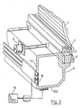
- the coating device according to the invention shown in the drawing serves for coating a material web 2, in particular a paper web, which is guided around a counter-roller 1 in the direction of the arrow.
- the coating material applied in excess to the web 1 by an application unit, not shown, is metered to the desired coat weight by the metering system described below.
- the dosing system contains a scraper knife 3, which rests with its tip against the web 2 and is fastened with its foot in a clamping bar 4.
- the clamping bar 4 is adjustably mounted in a scraper bar 5 by means of a spindle motor 6, the direction of movement of the clamping bar 4 being fixed approximately 70 ° -80 ° against the scraper knife 3.
- a support bar 7 is fastened to the scraper bar 5, which can be adjusted to a specific transverse profile with adjusting screws 8 arranged at regular intervals over the working width.
- the side frame 9, together with the scraper bar 5, can be pivoted away from the counter-roller 1 about an axis 12 for cleaning or for changing a scraper knife.
- the stops 13 are adjusted by means of screw jacks 14, which are adjusted by a control and regulating device 15.
- heating strips 16.1-16.5 are fastened over the entire working width and are supplied by a power source (not shown).
- the heating power of the heating tapes 16 is controlled by the control device 15 as a function of the cross profile of the coating weight.
- the heating tapes 16 arranged in the area of the edge of the scraper bar 5 opposite the scraper knife 3 are particularly advantageously so-called self-regulating heating tapes, the local heating power of which is set automatically as a function of the local temperature. These heating strips 16 are therefore able to set a uniform temperature over the entire working width on the two sides 5.1, 5.2 of the scraper bar 5 without any special control effort.
- Self-regulating heating tapes are known and are e.g. distributed by Raychem under the name "Auto-Trace" and are described in the catalog of the same name of this company.
- the heating strips 16 are connected to a uniform current source in order to ensure a uniform temperature on the sides 5.1, 5.2 of the doctor bar over the working width.
- the current output to the heating tapes 16 is set as a function of a preselected temperature difference between the doctor knife 3 and the pages 5.1, 5.2.
- temperature sensors are arranged on the side of the clamping bar 4 facing the counter roller 1 and the scraper bar sides 5.1, 5.2.
- the current output to the heating tapes 16 and thus their heating power is regulated as a function of the cross profile of the coating weight.
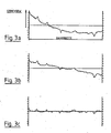
- the current, local line weight is measured at regular intervals across the working width and the deviation of the line weight distribution from a straight line is determined in defined sections, e.g. by integrating the corresponding local line weight values over the individual sections.
- the cross-section of the coating weight is measured using known measuring devices; e.g. traversing measuring devices that determine the coat weight via radiation absorption.
- the lateral ends can be curved relative to the center of the clamping bar 4 and thus influence the contact force of the doctor knife tip on the material web 2, which determines the application weight, and the doctor knife geometry in the corresponding areas.
- a straight line profile can thus be set very easily and without complex measurements of the individual causes over the working width.
- the control device 15 additionally adjusts the distance between the scraper bar 5 on both sides of the coating device regulated.
- screw jacks 14 are arranged on both lateral edges of the coating device, which can be controlled separately in order to be able to tilt the scraper bar 5 over a certain width by adjusting the stops 13.
- the slope of this straight line is determined by the control device, ie it is determined whether the coat weight increases from one side of the coating device to the other.
- the lateral stops 13 are now moved relative to one another by means of the screw jacks 14 until the straight line runs with the zero slope on the required line weight (FIG. 3 c).
- a doctor blade was used as the metering element, the use of other metering elements e.g. Roller scraper or a scraper bar, which are fastened in a scraper beam, is also possible.
- other metering elements e.g. Roller scraper or a scraper bar, which are fastened in a scraper beam
Landscapes
- Coating Apparatus (AREA)
- Paper (AREA)
- Application Of Or Painting With Fluid Materials (AREA)
- Diaphragms For Electromechanical Transducers (AREA)
- Control Of Direct Current Motors (AREA)
- Processing Of Solid Wastes (AREA)
- Road Repair (AREA)
Priority Applications (1)
| Application Number | Priority Date | Filing Date | Title |
|---|---|---|---|
| AT89122877T ATE91922T1 (de) | 1989-03-15 | 1989-12-12 | Verfahren und vorrichtung zum beschichten von materialbahnen, insbesondere von papier- oder kartonbahnen. |
Applications Claiming Priority (2)
| Application Number | Priority Date | Filing Date | Title |
|---|---|---|---|
| DE3908386A DE3908386A1 (de) | 1989-03-15 | 1989-03-15 | Verfahren und vorrichtung zum beschichten von materialbahnen, insbesondere von papier- oder kartonbahnen |
| DE3908386 | 1989-03-15 |
Publications (3)
| Publication Number | Publication Date |
|---|---|
| EP0387412A2 true EP0387412A2 (fr) | 1990-09-19 |
| EP0387412A3 EP0387412A3 (fr) | 1991-01-30 |
| EP0387412B1 EP0387412B1 (fr) | 1993-07-28 |
Family
ID=6376367
Family Applications (1)
| Application Number | Title | Priority Date | Filing Date |
|---|---|---|---|
| EP89122877A Expired - Lifetime EP0387412B1 (fr) | 1989-03-15 | 1989-12-12 | Procédé et dispositif pour revêtir une bande en particulier une bande de papier ou de carton |
Country Status (8)
| Country | Link |
|---|---|
| US (1) | US5074243A (fr) |
| EP (1) | EP0387412B1 (fr) |
| JP (1) | JP2868573B2 (fr) |
| AT (1) | ATE91922T1 (fr) |
| CA (1) | CA2007544C (fr) |
| DE (2) | DE3908386A1 (fr) |
| ES (1) | ES2051974T3 (fr) |
| FI (1) | FI106846B (fr) |
Cited By (5)
| Publication number | Priority date | Publication date | Assignee | Title |
|---|---|---|---|---|
| FR2670514A1 (fr) * | 1990-12-13 | 1992-06-19 | Valmet Paper Machinery Inc | Procede et dispositif pour compenser le flechissement d'une poutre de support de racle. |
| EP0533022A1 (fr) * | 1991-09-13 | 1993-03-24 | Kaukas Oy | Méthode de contrôle de l'accumulation de sauce de couchage sur une lame de station de couchage dans une machine d'enduction de papier |
| DE9214884U1 (de) * | 1992-10-28 | 1994-03-03 | Zimmer, Johannes, Klagenfurt | Rakeleinrichtung |
| DE19619250A1 (de) * | 1996-05-13 | 1997-11-20 | Voith Sulzer Papiermasch Gmbh | Vorrichtung und Verfahren zum direkten oder indirekten Auftragen eines flüssigen oder pastösen Mediums auf eine laufende Materialbahn, insbesondere aus Papier oder Karton |
| RU2720779C2 (ru) * | 2015-12-09 | 2020-05-13 | Бретье-Аутомацион Гмбх | Промазочное устройство |
Families Citing this family (16)
| Publication number | Priority date | Publication date | Assignee | Title |
|---|---|---|---|---|
| FI91025C (fi) * | 1991-02-08 | 1995-08-22 | Valmet Paper Machinery Inc | Menetelmä paperin tai muun rainamateriaalin päällystemäärän poikkiprofiilin säätämiseksi ja menetelmän toteuttamiseen tarkoitettu päällystysasema |
| US5480486A (en) * | 1993-12-21 | 1996-01-02 | Beloit Technologies, Inc. | Continuous adjustable backing bar for profiling coater blade |
| US5597415A (en) * | 1995-02-09 | 1997-01-28 | Voith Sulzer Paper Technology North America, Inc. | Profiling bar for a web coating device |
| DE19627456A1 (de) * | 1996-07-08 | 1998-01-15 | Voith Sulzer Papiermasch Gmbh | Auftragwerk zum direkten Auftragen eines flüssigen oder pastösen Mediums auf eine laufende Materialbahn, insbesondere aus Papier oder Karton |
| DE19631888A1 (de) * | 1996-08-07 | 1998-02-12 | Voith Sulzer Papiermasch Gmbh | Auftragwerk zum direkten oder indirekten Auftragen eines flüssigen oder pastösen Streichmediums auf eine laufende Materialbahn, insbesondere aus Papier oder Karton |
| DE19637164A1 (de) * | 1996-09-12 | 1998-03-19 | Voith Sulzer Papiermasch Gmbh | Verfahren und Vorrichtung zum direkten oder indirekten Auftragen eines flüssigen oder pastösen Mediums auf eine laufende Materialbahn |
| FI109215B (fi) | 1996-10-28 | 2002-06-14 | Metso Paper Inc | Menetelmä ja sovitelma liikkuvan paperi- tai kartonkiradan päällystämiseksi |
| DE19649559A1 (de) * | 1996-11-29 | 1998-06-04 | Voith Sulzer Papiermasch Gmbh | Vorrichtung zum direkten oder indirekten Auftragen eines flüssigen oder pastösen Streichmediums auf eine laufende Materialbahn |
| DE19801140A1 (de) * | 1998-01-14 | 1999-07-15 | Voith Sulzer Papiertech Patent | Vorrichtung zum direkten oder indirekten Auftrag eines flüssigen bis pastösen Auftragsmediums auf eine laufende Materialbahn sowie Betriebsverfahren für eine solche Vorrichtung |
| DE19821446A1 (de) * | 1998-05-13 | 1999-11-18 | Voith Sulzer Papiertech Patent | Vorrichtung zum Auftragen eines flüssigen oder pastösen Mediums auf eine laufende Materialbahn, insbesondere aus Papier oder Karton, und Maschine zur Papier- oder Kartonherstellung |
| DE19822505A1 (de) * | 1998-05-19 | 1999-11-25 | Voith Sulzer Papiertech Patent | Beschichtungsverfahren |
| DE19858653A1 (de) * | 1998-12-18 | 2000-06-21 | Voith Sulzer Papiertech Patent | Verfahren und Vorrichtung zum Auftragen eines flüssigen oder pastösen Auftragsmediums auf einen laufenden Untergrund |
| EP1150780B1 (fr) * | 1999-02-11 | 2003-01-15 | Alcan International Limited | Procede et appareil permettant de controler des profiles de machine a enduire directes |
| DE102004037532A1 (de) * | 2004-08-03 | 2006-03-16 | Voith Paper Patent Gmbh | Auftragsvorrichtung |
| DE102009002017A1 (de) | 2009-03-31 | 2010-10-07 | Voith Patent Gmbh | Vorrichtung und Verfahren zum Beschichten von Materialbahnen, insbesondere Papier- oder Kartonbahnen |
| DE102018009535A1 (de) | 2018-12-07 | 2020-06-10 | Andritz Küsters Gmbh | Auftragswerk zum direkten oder indirekten Auftragen eines Streichmediums |
Family Cites Families (10)
| Publication number | Priority date | Publication date | Assignee | Title |
|---|---|---|---|---|
| DE1012582B (de) * | 1952-09-18 | 1957-07-25 | Heinrich Nicolaus G M B H | Verfahren zur Herstellung von gleichmaessigen UEberzuegen auf Traegerstoffbahnen und Vorrichtung zur Durchfuehrung des Verfahrens |
| US3134126A (en) * | 1961-10-17 | 1964-05-26 | Beloit Corp | Deflection compensation for doctor backs |
| US3221357A (en) * | 1962-11-01 | 1965-12-07 | Bird Machine Co | Non-sweating doctor blade support |
| US3785340A (en) * | 1972-08-08 | 1974-01-15 | Beloit Corp | Metering bar |
| DE2825907B2 (de) * | 1978-06-13 | 1981-02-26 | Jagenberg-Werke Ag, 4000 Duesseldorf | Vorrichtung zum Aufbringen einer Beschichtung auf eine Materialbahn |
| DE2828339A1 (de) * | 1978-06-28 | 1980-01-17 | Schmidt Erwepa Maschf | Verfahren zur einstellung und aufrechterhaltung einer bestimmten durchbiegung des schaberbalkens an einem an einer seiner laengsseiten einer einseitigen erwaermung ausgesetzten, an einer walze, insbesondere einem glaett- oder trockenzylinder einer papiermaschine angeordneten schaber, sowie einrichtung zur durchfuehrung des verfahrens |
| DE2932839A1 (de) * | 1979-08-14 | 1981-03-12 | Adolf Siebert Gmbh & Co, 5270 Gummersbach | Rakel |
| DE3639665C1 (en) * | 1986-11-20 | 1987-12-03 | Santrade Ltd | Device for producing thin sheets from flowable materials, in particular from synthetic resin |
| DE3729621A1 (de) * | 1987-09-04 | 1989-03-16 | Jagenberg Ag | Vorrichtung zum beschichten einer um eine gegenwalze gefuehrten materialbahn |
| US4957770A (en) * | 1989-01-27 | 1990-09-18 | Measurex Corporation | Coating weight measuring and control apparatus and method |
-
1989
- 1989-03-15 DE DE3908386A patent/DE3908386A1/de not_active Withdrawn
- 1989-12-12 DE DE8989122877T patent/DE58905057D1/de not_active Expired - Fee Related
- 1989-12-12 AT AT89122877T patent/ATE91922T1/de not_active IP Right Cessation
- 1989-12-12 ES ES89122877T patent/ES2051974T3/es not_active Expired - Lifetime
- 1989-12-12 EP EP89122877A patent/EP0387412B1/fr not_active Expired - Lifetime
-
1990
- 1990-01-11 CA CA002007544A patent/CA2007544C/fr not_active Expired - Fee Related
- 1990-02-23 US US07/484,021 patent/US5074243A/en not_active Expired - Lifetime
- 1990-03-14 FI FI901284A patent/FI106846B/fi not_active IP Right Cessation
- 1990-03-14 JP JP2061311A patent/JP2868573B2/ja not_active Expired - Fee Related
Cited By (6)
| Publication number | Priority date | Publication date | Assignee | Title |
|---|---|---|---|---|
| FR2670514A1 (fr) * | 1990-12-13 | 1992-06-19 | Valmet Paper Machinery Inc | Procede et dispositif pour compenser le flechissement d'une poutre de support de racle. |
| EP0533022A1 (fr) * | 1991-09-13 | 1993-03-24 | Kaukas Oy | Méthode de contrôle de l'accumulation de sauce de couchage sur une lame de station de couchage dans une machine d'enduction de papier |
| DE9214884U1 (de) * | 1992-10-28 | 1994-03-03 | Zimmer, Johannes, Klagenfurt | Rakeleinrichtung |
| DE4337386C2 (de) * | 1992-10-28 | 2002-09-12 | Johannes Zimmer | Rakeleinrichtung |
| DE19619250A1 (de) * | 1996-05-13 | 1997-11-20 | Voith Sulzer Papiermasch Gmbh | Vorrichtung und Verfahren zum direkten oder indirekten Auftragen eines flüssigen oder pastösen Mediums auf eine laufende Materialbahn, insbesondere aus Papier oder Karton |
| RU2720779C2 (ru) * | 2015-12-09 | 2020-05-13 | Бретье-Аутомацион Гмбх | Промазочное устройство |
Also Published As
| Publication number | Publication date |
|---|---|
| FI106846B (fi) | 2001-04-30 |
| FI901284A0 (fi) | 1990-03-14 |
| DE3908386A1 (de) | 1990-09-27 |
| ATE91922T1 (de) | 1993-08-15 |
| EP0387412B1 (fr) | 1993-07-28 |
| ES2051974T3 (es) | 1994-07-01 |
| DE58905057D1 (de) | 1993-09-02 |
| CA2007544A1 (fr) | 1990-09-15 |
| JPH0330866A (ja) | 1991-02-08 |
| CA2007544C (fr) | 2000-05-02 |
| US5074243A (en) | 1991-12-24 |
| EP0387412A3 (fr) | 1991-01-30 |
| JP2868573B2 (ja) | 1999-03-10 |
Similar Documents
| Publication | Publication Date | Title |
|---|---|---|
| EP0387412B1 (fr) | Procédé et dispositif pour revêtir une bande en particulier une bande de papier ou de carton | |
| DE3729621C2 (fr) | ||
| DE19710549C2 (de) | Verfahren und Anlage zum Imprägnieren und Trocknen einer durchlaufenden Bahn | |
| DE3114056C2 (fr) | ||
| EP1040227B1 (fr) | Buse fendue pour enduire des bandes de materiau, notamment des bandes de papier ou de carton avec une sauce de couchage au pigment | |
| DE2825907B2 (de) | Vorrichtung zum Aufbringen einer Beschichtung auf eine Materialbahn | |
| DE2713917B2 (de) | Verfahren zum Erzielen einer über die gesamte Walzenlänge gleichbleibenden Stärke des Preßspaltes eines Kalanders | |
| DE2005655A1 (de) | Verfahren zur Ermittlung und Varianzen einer Eigenschaft eines bahnenförmigen Materials | |
| DE69307133T2 (de) | Riegelvorrichtung für einen walzenspalt | |
| DE3017274C2 (de) | Vorrichtung zum Streichen von Papierbahnen | |
| DE1588284A1 (de) | System zum Regeln der Dicke von Flachmaterialbahnen | |
| EP0352440B1 (fr) | Dispositif pour l'enduction en continu d'un matériau en bande passant sur un contre-rouleau | |
| DE3931793A1 (de) | Ein geraet zur beschichtung einer fahrenden bahn | |
| DE2913421B2 (de) | Verfahren und Vorrichtung zum Abstreifen von überschüssiger Streichmasse von einer laufenden Bahn | |
| DE69421922T2 (de) | Beschichtungsvorrichtung | |
| DE69026873T2 (de) | Verfahren zur Regelung und On-Line-Messung der Faserorientierung einer Bahn, gemacht auf einer Papiermaschine | |
| DE4334555C2 (de) | Halterung für eine Rakelstange | |
| EP0152810B1 (fr) | Procédé pour laminer des feuilles en aluminium | |
| DE2646897C2 (de) | Vorrichtung zur Einstellung des Liniendruckes bei Quetschwalzensystemen | |
| DE2329120A1 (de) | Verfahren und einrichtung zur gewinnung einer die istwerte einer messbaren eigenschaft eines materialstreifens in dessen querrichtung darstellenden wertefolge | |
| DE3532617A1 (de) | Klebstoffauftrager fuer einseitig gerippte aussteifungen | |
| DE4141214C2 (de) | Verfahren und Vorrichtung Ausgleichen von Biegungen eines Abstreifklingenträgers | |
| DE3929458C2 (fr) | ||
| DE69527024T2 (de) | Verfahren und Aufbau zur Überwachung des Beschichtungsprofils in Beschichtungsvorrichtungen, die auf einem Auftrag mit kurzer Wartezeit basieren | |
| EP0279173B1 (fr) | Dispositif pour mesurer des petites variations d'épaisseurs dans le profile des matériaux en forme de ruban, en particulier des papiers de base photographiques |
Legal Events
| Date | Code | Title | Description |
|---|---|---|---|
| PUAI | Public reference made under article 153(3) epc to a published international application that has entered the european phase |
Free format text: ORIGINAL CODE: 0009012 |
|
| AK | Designated contracting states |
Kind code of ref document: A2 Designated state(s): AT CH DE ES FR GB IT LI NL SE |
|
| PUAL | Search report despatched |
Free format text: ORIGINAL CODE: 0009013 |
|
| AK | Designated contracting states |
Kind code of ref document: A3 Designated state(s): AT CH DE ES FR GB IT LI NL SE |
|
| 17P | Request for examination filed |
Effective date: 19910104 |
|
| 17Q | First examination report despatched |
Effective date: 19920511 |
|
| GRAA | (expected) grant |
Free format text: ORIGINAL CODE: 0009210 |
|
| ITF | It: translation for a ep patent filed | ||
| AK | Designated contracting states |
Kind code of ref document: B1 Designated state(s): AT CH DE ES FR GB IT LI NL SE |
|
| REF | Corresponds to: |
Ref document number: 91922 Country of ref document: AT Date of ref document: 19930815 Kind code of ref document: T |
|
| REF | Corresponds to: |
Ref document number: 58905057 Country of ref document: DE Date of ref document: 19930902 |
|
| GBT | Gb: translation of ep patent filed (gb section 77(6)(a)/1977) |
Effective date: 19930810 |
|
| ET | Fr: translation filed | ||
| PGFP | Annual fee paid to national office [announced via postgrant information from national office to epo] |
Ref country code: CH Payment date: 19931115 Year of fee payment: 5 |
|
| PGFP | Annual fee paid to national office [announced via postgrant information from national office to epo] |
Ref country code: NL Payment date: 19931231 Year of fee payment: 5 |
|
| PLBE | No opposition filed within time limit |
Free format text: ORIGINAL CODE: 0009261 |
|
| STAA | Information on the status of an ep patent application or granted ep patent |
Free format text: STATUS: NO OPPOSITION FILED WITHIN TIME LIMIT |
|
| REG | Reference to a national code |
Ref country code: ES Ref legal event code: FG2A Ref document number: 2051974 Country of ref document: ES Kind code of ref document: T3 |
|
| 26N | No opposition filed | ||
| PG25 | Lapsed in a contracting state [announced via postgrant information from national office to epo] |
Ref country code: CH Effective date: 19941231 Ref country code: LI Effective date: 19941231 |
|
| EAL | Se: european patent in force in sweden |
Ref document number: 89122877.7 |
|
| PG25 | Lapsed in a contracting state [announced via postgrant information from national office to epo] |
Ref country code: NL Effective date: 19950701 |
|
| REG | Reference to a national code |
Ref country code: CH Ref legal event code: PL |
|
| NLV4 | Nl: lapsed or anulled due to non-payment of the annual fee |
Effective date: 19950701 |
|
| PGFP | Annual fee paid to national office [announced via postgrant information from national office to epo] |
Ref country code: GB Payment date: 20011116 Year of fee payment: 13 |
|
| REG | Reference to a national code |
Ref country code: GB Ref legal event code: IF02 |
|
| PG25 | Lapsed in a contracting state [announced via postgrant information from national office to epo] |
Ref country code: GB Free format text: LAPSE BECAUSE OF NON-PAYMENT OF DUE FEES Effective date: 20021212 |
|
| PGFP | Annual fee paid to national office [announced via postgrant information from national office to epo] |
Ref country code: ES Payment date: 20021212 Year of fee payment: 14 |
|
| PGFP | Annual fee paid to national office [announced via postgrant information from national office to epo] |
Ref country code: FR Payment date: 20021217 Year of fee payment: 14 |
|
| GBPC | Gb: european patent ceased through non-payment of renewal fee | ||
| PG25 | Lapsed in a contracting state [announced via postgrant information from national office to epo] |
Ref country code: ES Free format text: LAPSE BECAUSE OF NON-PAYMENT OF DUE FEES Effective date: 20031213 |
|
| PG25 | Lapsed in a contracting state [announced via postgrant information from national office to epo] |
Ref country code: FR Free format text: LAPSE BECAUSE OF NON-PAYMENT OF DUE FEES Effective date: 20040831 |
|
| REG | Reference to a national code |
Ref country code: FR Ref legal event code: ST |
|
| REG | Reference to a national code |
Ref country code: ES Ref legal event code: FD2A Effective date: 20031213 |
|
| PG25 | Lapsed in a contracting state [announced via postgrant information from national office to epo] |
Ref country code: IT Free format text: LAPSE BECAUSE OF NON-PAYMENT OF DUE FEES;WARNING: LAPSES OF ITALIAN PATENTS WITH EFFECTIVE DATE BEFORE 2007 MAY HAVE OCCURRED AT ANY TIME BEFORE 2007. THE CORRECT EFFECTIVE DATE MAY BE DIFFERENT FROM THE ONE RECORDED. Effective date: 20051212 |
|
| PGFP | Annual fee paid to national office [announced via postgrant information from national office to epo] |
Ref country code: AT Payment date: 20071221 Year of fee payment: 19 |
|
| PGFP | Annual fee paid to national office [announced via postgrant information from national office to epo] |
Ref country code: SE Payment date: 20071213 Year of fee payment: 19 |
|
| PGFP | Annual fee paid to national office [announced via postgrant information from national office to epo] |
Ref country code: DE Payment date: 20071221 Year of fee payment: 19 |
|
| EUG | Se: european patent has lapsed | ||
| PG25 | Lapsed in a contracting state [announced via postgrant information from national office to epo] |
Ref country code: AT Free format text: LAPSE BECAUSE OF NON-PAYMENT OF DUE FEES Effective date: 20081212 |
|
| PG25 | Lapsed in a contracting state [announced via postgrant information from national office to epo] |
Ref country code: DE Free format text: LAPSE BECAUSE OF NON-PAYMENT OF DUE FEES Effective date: 20090701 |
|
| PG25 | Lapsed in a contracting state [announced via postgrant information from national office to epo] |
Ref country code: SE Free format text: LAPSE BECAUSE OF NON-PAYMENT OF DUE FEES Effective date: 20081213 |