EP0387524A2 - Vanne de commande de débit à deux voies - Google Patents
Vanne de commande de débit à deux voiesInfo
- Publication number
- EP0387524A2 EP0387524A2 EP90102660A EP90102660A EP0387524A2 EP 0387524 A2 EP0387524 A2 EP 0387524A2 EP 90102660 A EP90102660 A EP 90102660A EP 90102660 A EP90102660 A EP 90102660A EP 0387524 A2 EP0387524 A2 EP 0387524A2
- Authority
- EP
- European Patent Office
- Prior art keywords
- valve
- pressure chamber
- pressure
- control piston
- valve according
- Prior art date
- Legal status (The legal status is an assumption and is not a legal conclusion. Google has not performed a legal analysis and makes no representation as to the accuracy of the status listed.)
- Granted
Links
Images
Classifications
-
- G—PHYSICS
- G05—CONTROLLING; REGULATING
- G05D—SYSTEMS FOR CONTROLLING OR REGULATING NON-ELECTRIC VARIABLES
- G05D7/00—Control of flow
- G05D7/01—Control of flow without auxiliary power
- G05D7/0126—Control of flow without auxiliary power the sensing element being a piston or plunger associated with one or more springs
-
- Y—GENERAL TAGGING OF NEW TECHNOLOGICAL DEVELOPMENTS; GENERAL TAGGING OF CROSS-SECTIONAL TECHNOLOGIES SPANNING OVER SEVERAL SECTIONS OF THE IPC; TECHNICAL SUBJECTS COVERED BY FORMER USPC CROSS-REFERENCE ART COLLECTIONS [XRACs] AND DIGESTS
- Y10—TECHNICAL SUBJECTS COVERED BY FORMER USPC
- Y10T—TECHNICAL SUBJECTS COVERED BY FORMER US CLASSIFICATION
- Y10T137/00—Fluid handling
- Y10T137/7722—Line condition change responsive valves
- Y10T137/7781—With separate connected fluid reactor surface
- Y10T137/7784—Responsive to change in rate of fluid flow
- Y10T137/7787—Expansible chamber subject to differential pressures
- Y10T137/7788—Pressures across fixed choke
Definitions
- the invention relates to a valve, in particular a 2-way flow control valve according to the features of the preamble of claim 1.
- the flow control valves commonly available on the market today are, on the one hand, cartridge-type valves, which are generally designed as so-called constant-flow control valves, and, on the other hand, flow-control valves in housing construction.
- the adjustment volume flow can be changed over the entire area of application without the exchange of such orifice plates.
- a flow control valve which is of the same type as the valve according to the invention, is previously known from DE 32 11 545 A1.
- the valve shown there in FIG. 5 has a compensating bore in the means for freely adjusting the amount of the flow in the form of an adjustable measuring orifice, by means of which the pressure present at the inlet of the valve can be detected.
- This compensating bore which has a throttling point in its interior, is connected to a control device by means of which the measuring orifice can be controlled for an opening or closing movement at the inlet of the valve.
- the actuator (control piston) of this known valve by means of which the amount of the flow rate can be regulated at its outlet, is exposed to the action of the pressure at the inlet, the force of a force accumulator in the form of a spring, and the pressure at the outlet of the valve, which auxiliary bores additionally arranged in the housing of the valve are guided into the valve chamber in which the actuator moves.
- This known design is also complex and volume-consuming due to the auxiliary bores in the design.
- a non-generic valve is known, the means for freely adjusting the amount of the flow stream are formed from an adjustable spindle which engages with its conical end part in a through bore of the actuator (control piston).
- This known valve does not have any additional means for detecting the pressure present at the inlet of the valve in the form of a compensating bore.
- valve which can be used for the control of cold water coolers in underground construction, is known from DE 31 19 406 A1, the means for freely adjusting the amount of flow rate is formed from a variable slot cross section in the actuator. Additional means for detecting the pressure at the inlet in the form of a compensating hole are also not available here.
- the valve is large and the flow of the fluid, which is deflected twice in the area of the control piston on the way to the outlet of the valve, is unfavorable.
- the object of the invention is to create a valve of small size which is favorable in terms of flow behavior and which can be designed as an installation kit in both the cartridge and the housing construction, the volume flow being freely adjustable over the entire area of application while maintaining a predefinable control characteristic curve, without that complex external auxiliary bores, ring channels or uncontrollable double guides are used in their properties.
- the amount of fluid flowing through the valve can also be kept constant along a predeterminable control characteristic curve, specifically over the entire range of the pressure-dependent volume flow that can be freely adjusted with the means provided for this purpose, even if volume flow changes at the inlet and / or outlet of the Valve occur.
- a predeterminable control characteristic curve specifically over the entire range of the pressure-dependent volume flow that can be freely adjusted with the means provided for this purpose, even if volume flow changes at the inlet and / or outlet of the Valve occur.
- the means for freely adjusting the volume flow are formed from a measuring orifice which has a slot which, according to claim 7, has at least two flanks which end at at least one connecting line at an acute angle to one another, this results in a fine resolution possible when setting the flow rate of the valve.
- the receiving bore in the valve housing or in the cartridge consists of individual bores, the diameter of which decrease in the direction of the measuring orifice, insofar as the valve according to the invention is inserted into the receiving bore, there is a receiving bore which can be produced by means of a one-sided and thus inexpensive drilling method.
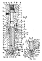
- Fig. 1 shows the valve according to the invention, which is received in a receiving bore 10 of a valve housing 12.
- a cartridge could also be used, in which the receiving bore runs accordingly.
- the valve has a throttle spindle 14, along whose longitudinal axis 16 and in its lower half a compensating bore 18 runs, the lower end 20 of which, seen in FIG. 1, opens into the environment, whereas the upper end 22, seen in FIG. 1, of two 1 seen horizontally extending transverse bores 24 is connected to a first pressure chamber 26.
- this first pressure chamber 26 is subdivided into an upper sub-chamber 28 and into a lower sub-chamber 30 by means of a control piston 32, which can also be referred to in technical terms as a pressure compensator.
- this control piston 32 has two connecting bores 34 at the location of the first pressure chamber 26, which connect the upper part 28 to the lower part 30.
- the control piston 32 is arranged within this first pressure chamber 26, guided along the wall 36 of the receiving bore 10 and the outer wall 38 of the throttle spindle 14, so that it can be moved longitudinally.
- the control piston 32 is essentially T-shaped and has a through bore 40 in its longitudinal direction for receiving the throttle spindle 14.
- the longitudinal bar of the T-shaped control piston 32 is more precisely guided along a wall section 36b of the wall 36 of the receiving bore 10, whereas the disk-shaped transverse bar is guided on its outer circumference along a wall section 36d, the diameter of which is larger than that of the wall portion 36b.
- the movement of the control piston 32 during its longitudinal movement, as shown in particular in FIG. 1, is limited by an upper stop 42 and a lower stop 44.
- the upper stop 42 is formed by the lower side wall 46 of a ring 48, as seen in FIG.
- valve body 50 which is part of a valve body 50, which can be screwed into a thread 54 by means of an external thread 52, which thread consists of a wall section 36e of the wall 36 of the receiving bore 10 is formed.
- 1 shows the valve body 50 in its screwed-in position, which it assumes after installation in the valve housing 12.
- the interior of the valve can be sealed by means of an annular seal 56, which is arranged in a receptacle 58 of the valve housing 50.
- the lower stop 44 is formed from a shoulder in the wall 36 of the receiving bore 10, which results from the different bore diameters of the wall sections 36d and 36c, the latter wall section 36c in terms of the size of its diameter between the bore diameters of the wall sections 36b and 36d of the wall 36 lies and is chosen so large that between the wall section 36c and the outer wall of the longitudinal beam of the T-shaped control piston 32 an energy store in the form of a compression spring 60 can be arranged.
- the control piston 32 has three surfaces 62a, b and c which can be acted upon by a fluid, the upper surface 62a of the control piston 32 facing the upper stop 42 being the largest, as seen in FIG. 1, whereas the one downstream in FIG. 1 is the largest surface 62b arranged on the crossbar of the T-shaped control piston 32 is the middle surface and the smallest surface 62c is arranged at the lower end of the control piston 32 as seen in FIG. If the surface areas of the smallest area 62c and the middle area 62b are added together, the area of the largest piston area 62a of the control piston 32 is approximately obtained.
- the compression spring 60 which with its in FIG. 1, the upper end is supported against the central surface 62b and with its other end against a shoulder 64 in the wall 36 of the receiving bore 10, the control piston 32 against the fixed upper stop 42, which is formed by the valve body 50 which is fixedly connected to the valve housing 12 is.
- the upper subspace 28 of the first pressure chamber 26 is formed by a cavity 66 which is delimited by an inner wall 68 of the valve body 50 and the outer wall 38 of the throttle spindle 14 and the surface 62a.
- the throttle spindle 14 is guided in a central bore 71 of the valve body 50 and extends over the entire length of the valve body 50. In its position shown in FIG. 1, it is in one of its extended positions. At its upper end, as seen in FIG. 1, the throttle spindle 14 has a measuring scale 72 which is provided with the measuring stages "1" to "5" shown in FIG. 1 and from which half values can also be read due to the cross hatching.
- This measuring scale 72 is connected to a longitudinal guide part 74, which has individual longitudinal guides 76, which run parallel to the longitudinal axis 16 of the housing and which are guided in correspondingly shaped grooves in a union part 78.
- This coupling part 78 is rotatably and axially displaceably guided in the recess 80 of an adjusting part 82 which is provided for the actuation of the throttle spindle 14 by hand.
- the coupling part 78 which serves to guide the longitudinal guide part 74 of the throttle spindle 14, is supported on the upper side of the valve body 50.
- the control part 82 engages around the upper end of the valve body 50 as seen in FIG. 1 and is rotatably but non-displaceably connected to the latter via axially releasable pin connections 84 in the direction of the longitudinal axis 16 thereof.
- the actuating part 82 has on its upper side a passage 86 which is surrounded by a measuring plate 88, the surface of which is machined in the horizontal plane facilitates the reading of the measuring scale 72, provided that this is scaled with the upper side of the measuring plate 88 lies in a plane or extends beyond it.
- multi-start threads can also be used, which can be designed in such a way that a different transmission ratio results here, that is to say, for example, with a smaller number of revolutions on the adjusting part 82, there is a larger adjustment path of the throttle spindle 14 or the like.
- the throttle spindle 14 below its threaded section 90 has a collar 94 with a reduced diameter, on which a sealing ring 96 is arranged, which seals the first pressure chamber 26 from the environment.
- connection 100 which represents the inlet of the valve and which is connected to an assembly via a line (not shown) , for example to a hydraulic pump which can be driven by a motor and which transfers fluid to the connection 100 under a certain pressure and in a certain amount.
- This connection 100 is formed from a bore in the valve housing 12, the wall section 36a of which has a diameter that is smaller than that of the wall section 36b of the receiving bore 10 that follows upward in FIG. 1.
- this second pressure chamber 102 opens into a second pressure chamber 102, which extends from the smallest piston surface 62c of the control piston 32 and part of the wall section 36b of the wall 36 of the receiving bore 10 and through the end piece 98 of the Throttle spindle 14 is limited and forms the outlet of the valve. Furthermore, this second pressure chamber 102 has a further connection 104, the diameter of which essentially corresponds to the diameter of the connection 100 and which is connected via a line (not shown) to a fluid collector, for example in the form of a hydraulic pump (not shown).
- the throttle spindle 14 is correspondingly tapered for engagement in this connection.
- the lower end of the throttle spindle 14 is, as will be described in the following, designed in such a way that it together with the edge 106, which is formed at the location of the transition between the wall section 36a and the wall section 36b of the receiving bore 10, has one as a whole 108 designated orifice.
- the throttle spindle 14 has a slot 110 on its lower end piece, which extends essentially horizontally and perpendicular to the longitudinal axis 16 of the valve and extends continuously through the lower end of the throttle spindle 14.
- This slot 110 opens into the connection 100 with its lower end 112 as seen in FIGS. 1 and 2.
- the slot 110 consists of pairs of slot halves 114a, b and 116a, b lying opposite one another in each case, wherein in FIG.
- a channel 118 which opens into the connection 100 and thus connects the compensating bore 18 to the connection 100.
- the walls 117a, b and 119a, b of the two slit half pairs 114a, b and 116a, b run at their upper ends as seen in FIGS. 1 and 2 over the two flank pairs 120a, b and 122a, b in a connecting line 124a and 124b together, which lie on a fictitious connecting line 124 which is essentially horizontal and perpendicular to the longitudinal axis 16 of the throttle spindle 14 and the valve.
- the outlet of the valve is thus formed by the second pressure chamber 102, which directly adjoins the intermediate spaces 126a, b, insofar as these protrude upward beyond the edge 12 of the valve.
- the connecting line 124 moves upwards away from the edge 106 in its positions shown in FIGS. 1 and 2 by means of the throttle spindle 14, the greater the distance between the respective flank pair 120a, b and 122a, b Above the edge 106 from each other and the larger the gap 126a or 126b located above the edge 106, so that the amount of fluid arriving from the connection 100 is increasingly directed into the second pressure chamber 102 as the throttle spindle 14 moves into the valve.
- the two flank pairs 120a, b and 122a, b take their greatest possible distance from one another at the location of the edge 106 and then the wall sections of the walls running parallel to one another and parallel to the longitudinal axis 16 are immersed 117a, b and 119a, b above the edge 106, whereby the flow rate increases further.
- the valve according to the invention is set so that the throttle spindle 14 with its end piece 98, regardless of the volume setting, still partially projects into the connection 100, so that the amount of fluid is forced to flow through the orifice plate 108. If the throttle spindle 14 were also raised, the end piece 98 would disengage from the connection 100 and the fluid would flow bypassing the measuring orifice 108 directly into the connection 104 via the second pressure chamber 102.
- the control piston 32 closes with its lower effective surface 62c essentially with that in FIG 1 seen from upper bore wall 130 of the connection 104.
- the point at which the connection 104 opens into the second pressure chamber 102 can be closed by the control piston 32, so that a control orifice 132 is formed at the point where the connection 104 opens into the second pressure chamber 102, by means of which the flow rate of the through the valve flowing through fluid is adjustable.
- the flow control valve is used in a hydraulic circuit in which pressure fluctuations can occur depending on the load.
- Fig. 1 the valve is shown in its unactuated position.
- the control piston 32 is pressed against the upper stop 42 of the valve body 50 by means of the compression spring 60.
- the fluid under connection at a certain pressure flows through the channel 118, the compensating bore 18 and the transverse bores 24 into the upper subspace 28 and from there via the connecting bores 34 into the lower subspace 30 of the first pressure chamber 26.
- the whole the first pressure chamber 26 to the pressure acting in the connection 100, which acts on the surfaces 62a and 62b of the control piston 32.
- the effective surface 62c of the control piston 32 essentially closes with the top of the bore wall 130 of the connection 104.
- the connecting line 124 lies essentially in the plane with the edge 106 of the valve housing 12, so that no fluid provided in the connection 100 and under pressure is in the second pressure chamber 102 via the spaces 126a, b and thus can be discharged via the further connection 104 if necessary.
- the measuring scale 72 is located below the measuring plate 88, so that the operator can see from this that the valve is in its unactuated position.
- the throttle spindle 14 is lifted upwards as a result of the threaded portion 90 in FIG. 1, by means of the union part 78 connected to the actuating part 82, which is in engagement with the longitudinal guide part 74 one of their retracted positions moves.
- the connecting line 124 in FIG. 1 moves away from the edge 106 of the valve housing 12 and takes up the position shown in FIG. 2, for example. In this position, the measuring orifice 108 clears the way for the pressurized fluid via the channel 118 of the compensating bore 18 into the second pressure chamber 102 and thus towards the further connection 104.
- the throttle spindle 14 is moved in via the actuating part 82, the more the connecting line 124 moves upward away from the edge 106 and the greater the amount of fluid that flows into the second pressure chamber via the two slot halves 114a, b and 116a, b 102 and thus flows over the connection 104.
- the purpose of such flow valves is to keep the flow constant regardless of the pressure difference between the valve inlet and outlet, so that the oil flow once set remains constant even in the event of pressure fluctuations.
- the fluid under pressure in the connection 100 is passed via the two transverse bores 24 into the first pressure chamber 26 and this pressure chamber is divided into two sub-chambers 28 and 30, which are connected via connecting bores 34 are connected in the control piston 32, the pressure of the fluid prevailing in the connection 100 is established in these two partial spaces 28 and 30 of the first pressure chamber 26 and thus on the two surfaces 62a and 62b of the control piston 32.
- connection 100 flows with a predeterminable pressure via the two pairs of slot halves 114a, b and 116a, b into the second pressure chamber 102.
- further connection 104 has essentially changed its bore diameter in relation to its effective cross-sectional area in relation to the effective cross-sectional area, a different pressure also arises in this connection 104 than in the second pressure chamber 102. If the valve according to the invention is now in its position shown in FIG.
- connection 100 the pressure consumer connected via the connection 104 is supplied with a fluid in a certain quantity and with a constant pressure, the connection 100 pressure present is greater than that in the pressure chamber 102, which in turn is greater than the pressure prevailing in the connection 104. There is therefore a decreasing pressure drop in the direction of the connection 104.
- port 100 due to the hydraulic system in which the valve according to the invention is used, an increase in volume flow, which, if the control piston 32 would not be present, would be passed on directly via the second pressure chamber 102 and the port 104 of the valve, increases the pressure at the inlet 100 of the valve, which also causes an increase in pressure in the first pressure chamber 26 due to the compensating bore 18.
- the pressure prevailing at the connection 100 is now equally present in the upper and lower subspaces 28 and 30 of the first pressure chamber 26 and thus equally on the surfaces 62a and 62b of the control piston 32, the only effective surface of the pressure compensator formed by the control piston 32 is the surface 62c of the control piston.
- the pressure present in the first pressure chamber 26 is now greater than the pressure which prevails when the valve assumes its position shown in FIG. 1 and, due to the balance of forces occurring on the control piston 32, causes this to be seen in FIGS. 1 and 2 moves below, the free cross section of the control orifice 132 is reduced.
- the desired volume flow on the downstream control orifice 132 is regulated as a function of the orifice cross section which can be freely adjusted by means of the throttle. Since the control orifice 132 is now reduced in cross section, the volume flow flowing through this control orifice also decreases.
- the control piston 32 thus adjusts itself, depending on the balance of forces prevailing at it, to a position in which the flow through the valve is constant.
- the slot 110 is designed as a notch slot, which has two flanks that converge at an acute angle, which allows a particularly fine control option for the valve for the flow stream.
- this notch slot shown in FIGS. 1 and 2 other slot courses are also conceivable, in which the notch base is designed differently, for example in cross section not triangular as shown in FIGS. 1 and 2, but rectangular or the like.
Landscapes
- Physics & Mathematics (AREA)
- General Physics & Mathematics (AREA)
- Engineering & Computer Science (AREA)
- Automation & Control Theory (AREA)
- Flow Control (AREA)
- Fluid-Pressure Circuits (AREA)
- Lift Valve (AREA)
- Fluid-Driven Valves (AREA)
- Infusion, Injection, And Reservoir Apparatuses (AREA)
- Control Of Combustion (AREA)
Applications Claiming Priority (2)
| Application Number | Priority Date | Filing Date | Title |
|---|---|---|---|
| DE3908377A DE3908377A1 (de) | 1989-03-15 | 1989-03-15 | 2-wege-stromventil |
| DE3908377 | 1989-03-15 |
Publications (3)
| Publication Number | Publication Date |
|---|---|
| EP0387524A2 true EP0387524A2 (fr) | 1990-09-19 |
| EP0387524A3 EP0387524A3 (fr) | 1992-02-12 |
| EP0387524B1 EP0387524B1 (fr) | 1994-09-14 |
Family
ID=6376364
Family Applications (1)
| Application Number | Title | Priority Date | Filing Date |
|---|---|---|---|
| EP90102660A Expired - Lifetime EP0387524B1 (fr) | 1989-03-15 | 1990-02-12 | Vanne de commande de débit à deux voies |
Country Status (4)
| Country | Link |
|---|---|
| US (1) | US5004006A (fr) |
| EP (1) | EP0387524B1 (fr) |
| AT (1) | ATE111615T1 (fr) |
| DE (2) | DE3908377A1 (fr) |
Cited By (1)
| Publication number | Priority date | Publication date | Assignee | Title |
|---|---|---|---|---|
| WO1999010791A1 (fr) * | 1997-08-22 | 1999-03-04 | Vickers, Incorporated | Soupape regulatrice de debit a pression egalisee |
Families Citing this family (3)
| Publication number | Priority date | Publication date | Assignee | Title |
|---|---|---|---|---|
| US5878766A (en) * | 1997-10-20 | 1999-03-09 | Vickers, Incorporated | Pressure compensated flow control valve |
| WO2007127949A2 (fr) | 2006-04-27 | 2007-11-08 | Sko Flo Industries, Inc. | Soupape de regulation de debit |
| WO2007127986A2 (fr) * | 2006-04-28 | 2007-11-08 | Sko Flo Industries, Inc. | Appareil de mesure d'écoulement |
Family Cites Families (11)
| Publication number | Priority date | Publication date | Assignee | Title |
|---|---|---|---|---|
| US2865397A (en) * | 1954-10-06 | 1958-12-23 | United States Steel Corp | Hydraulic governor |
| US3428080A (en) * | 1966-02-21 | 1969-02-18 | Fisher Governor Co | Flow control device |
| DE2432823A1 (de) * | 1974-07-09 | 1976-01-29 | Meier & Freimuth Ohg | Einstellbares stromregelventil |
| US4066096A (en) * | 1975-07-25 | 1978-01-03 | Aqueduct, Inc. | Flow-control valve |
| US4074693A (en) * | 1976-07-26 | 1978-02-21 | The W. A. Kates Company | Readily disassembleable fluid flow rate controller |
| US4080993A (en) * | 1976-09-13 | 1978-03-28 | Aqueduct, Inc. | In-line flow-control valve |
| JPS5471432A (en) * | 1977-11-17 | 1979-06-08 | Sotokazu Rikuta | Flow rate constant value automatic control valve |
| DE2917851A1 (de) * | 1979-05-03 | 1980-11-13 | Hebben Rolf Dipl Volksw | Hydraulisches mengenregelventil, insbesondere fuer wasserdirektverteiler von im untertagebetrieb eingesetzten schraemmaschinen |
| DE3119406A1 (de) * | 1981-05-15 | 1982-12-09 | Manfred Ing.(grad.) 4320 Hattingen Fischbach | Hydraulisches mengenregelventil, z.b. fuer die steuerung von kaltwasser-kuehlern im untertagebergbau |
| DE3211545A1 (de) * | 1982-03-29 | 1983-10-06 | Kracht Pumpen Motoren | Hydraulikventil zur druckmittelversorgung eines verbrauchers, insbesondere mengenregelventil |
| US4669495A (en) * | 1986-01-06 | 1987-06-02 | Fluid Controls, Inc. | Adjustable flow regulating valve |
-
1989
- 1989-03-15 DE DE3908377A patent/DE3908377A1/de not_active Withdrawn
-
1990
- 1990-02-12 DE DE59007094T patent/DE59007094D1/de not_active Expired - Fee Related
- 1990-02-12 AT AT90102660T patent/ATE111615T1/de not_active IP Right Cessation
- 1990-02-12 EP EP90102660A patent/EP0387524B1/fr not_active Expired - Lifetime
- 1990-03-08 US US07/490,377 patent/US5004006A/en not_active Expired - Lifetime
Cited By (1)
| Publication number | Priority date | Publication date | Assignee | Title |
|---|---|---|---|---|
| WO1999010791A1 (fr) * | 1997-08-22 | 1999-03-04 | Vickers, Incorporated | Soupape regulatrice de debit a pression egalisee |
Also Published As
| Publication number | Publication date |
|---|---|
| DE59007094D1 (de) | 1994-10-20 |
| EP0387524A3 (fr) | 1992-02-12 |
| US5004006A (en) | 1991-04-02 |
| ATE111615T1 (de) | 1994-09-15 |
| DE3908377A1 (de) | 1990-09-27 |
| EP0387524B1 (fr) | 1994-09-14 |
Similar Documents
| Publication | Publication Date | Title |
|---|---|---|
| DE1601729C3 (de) | Mit Vorsteuerung arbeitende hydraulische Steuerventileinrichtung | |
| DE60304663T2 (de) | Hydraulische Ventileinrichtung | |
| EP0650558B1 (fr) | Dispositif de commande pour au moins un consommateur hydraulique | |
| DE10027382A1 (de) | Hydraulische Steuereinrichtung | |
| DE2032395B2 (de) | Steuereinrichtung fuer ein hydraulisch betriebenes stellglied | |
| EP3106720A1 (fr) | Dispositif de commutation en forme de robinet a tournant spherique | |
| DE2319698A1 (de) | Regelventil | |
| DE3611973C2 (de) | Nebenschlußventil | |
| EP0387524B1 (fr) | Vanne de commande de débit à deux voies | |
| EP0121600B1 (fr) | Soupape de commande | |
| DE3919175C2 (fr) | ||
| DE19829530B4 (de) | Ventilanordnung | |
| EP2411679B1 (fr) | Dispositif de soupape hydraulique | |
| DE4234037C2 (de) | Ventilanordnung, insbesondere für mobile Arbeitsgeräte | |
| DE29508392U1 (de) | Elektrohydraulisches Hubmodul | |
| WO1994011797A1 (fr) | Dispositif de commande electrohydraulique et vanne de detente | |
| DE10156500C5 (de) | Druckminderungsventil | |
| DE102009016198B4 (de) | Fluidbetätigter Linearantrieb mit Endlagendämpfung | |
| EP0164438A1 (fr) | Clapet hydraulique | |
| DE3840328A1 (de) | Vorgesteuertes wegeventil | |
| DE3909291C2 (de) | Wegesteuerventil mit Druckwaage | |
| DE3622925C2 (de) | Kombiniertes Umschalt- und Druckbegrenzungsventil | |
| DE3908721C2 (fr) | ||
| DE3911204C2 (fr) | ||
| DE3006994C2 (fr) |
Legal Events
| Date | Code | Title | Description |
|---|---|---|---|
| PUAI | Public reference made under article 153(3) epc to a published international application that has entered the european phase |
Free format text: ORIGINAL CODE: 0009012 |
|
| AK | Designated contracting states |
Kind code of ref document: A2 Designated state(s): AT CH DE FR GB IT LI SE |
|
| PUAL | Search report despatched |
Free format text: ORIGINAL CODE: 0009013 |
|
| AK | Designated contracting states |
Kind code of ref document: A3 Designated state(s): AT CH DE FR GB IT LI SE |
|
| 17P | Request for examination filed |
Effective date: 19920118 |
|
| 17Q | First examination report despatched |
Effective date: 19940221 |
|
| GRAA | (expected) grant |
Free format text: ORIGINAL CODE: 0009210 |
|
| AK | Designated contracting states |
Kind code of ref document: B1 Designated state(s): AT CH DE FR GB IT LI SE |
|
| REF | Corresponds to: |
Ref document number: 111615 Country of ref document: AT Date of ref document: 19940915 Kind code of ref document: T |
|
| ITF | It: translation for a ep patent filed | ||
| REF | Corresponds to: |
Ref document number: 59007094 Country of ref document: DE Date of ref document: 19941020 |
|
| GBT | Gb: translation of ep patent filed (gb section 77(6)(a)/1977) |
Effective date: 19940922 |
|
| EAL | Se: european patent in force in sweden |
Ref document number: 90102660.9 |
|
| ET | Fr: translation filed | ||
| PLBE | No opposition filed within time limit |
Free format text: ORIGINAL CODE: 0009261 |
|
| STAA | Information on the status of an ep patent application or granted ep patent |
Free format text: STATUS: NO OPPOSITION FILED WITHIN TIME LIMIT |
|
| 26N | No opposition filed | ||
| REG | Reference to a national code |
Ref country code: GB Ref legal event code: IF02 |
|
| PGFP | Annual fee paid to national office [announced via postgrant information from national office to epo] |
Ref country code: GB Payment date: 20050113 Year of fee payment: 16 |
|
| PGFP | Annual fee paid to national office [announced via postgrant information from national office to epo] |
Ref country code: SE Payment date: 20050215 Year of fee payment: 16 |
|
| PGFP | Annual fee paid to national office [announced via postgrant information from national office to epo] |
Ref country code: CH Payment date: 20050218 Year of fee payment: 16 |
|
| PGFP | Annual fee paid to national office [announced via postgrant information from national office to epo] |
Ref country code: DE Payment date: 20050223 Year of fee payment: 16 |
|
| PGFP | Annual fee paid to national office [announced via postgrant information from national office to epo] |
Ref country code: AT Payment date: 20050224 Year of fee payment: 16 |
|
| PGFP | Annual fee paid to national office [announced via postgrant information from national office to epo] |
Ref country code: FR Payment date: 20050228 Year of fee payment: 16 |
|
| PG25 | Lapsed in a contracting state [announced via postgrant information from national office to epo] |
Ref country code: GB Free format text: LAPSE BECAUSE OF NON-PAYMENT OF DUE FEES Effective date: 20060212 Ref country code: AT Free format text: LAPSE BECAUSE OF NON-PAYMENT OF DUE FEES Effective date: 20060212 |
|
| PG25 | Lapsed in a contracting state [announced via postgrant information from national office to epo] |
Ref country code: SE Free format text: LAPSE BECAUSE OF NON-PAYMENT OF DUE FEES Effective date: 20060213 |
|
| PG25 | Lapsed in a contracting state [announced via postgrant information from national office to epo] |
Ref country code: LI Free format text: LAPSE BECAUSE OF NON-PAYMENT OF DUE FEES Effective date: 20060228 Ref country code: CH Free format text: LAPSE BECAUSE OF NON-PAYMENT OF DUE FEES Effective date: 20060228 |
|
| PGFP | Annual fee paid to national office [announced via postgrant information from national office to epo] |
Ref country code: IT Payment date: 20060228 Year of fee payment: 17 |
|
| PG25 | Lapsed in a contracting state [announced via postgrant information from national office to epo] |
Ref country code: DE Free format text: LAPSE BECAUSE OF NON-PAYMENT OF DUE FEES Effective date: 20060901 |
|
| REG | Reference to a national code |
Ref country code: CH Ref legal event code: PL |
|
| EUG | Se: european patent has lapsed | ||
| GBPC | Gb: european patent ceased through non-payment of renewal fee |
Effective date: 20060212 |
|
| REG | Reference to a national code |
Ref country code: FR Ref legal event code: ST Effective date: 20061031 |
|
| PG25 | Lapsed in a contracting state [announced via postgrant information from national office to epo] |
Ref country code: FR Free format text: LAPSE BECAUSE OF NON-PAYMENT OF DUE FEES Effective date: 20060228 |
|
| PG25 | Lapsed in a contracting state [announced via postgrant information from national office to epo] |
Ref country code: IT Free format text: LAPSE BECAUSE OF NON-PAYMENT OF DUE FEES Effective date: 20070212 |