EP0387684A2 - Appareil et méthode pour analyser, à l'aide de rayonnement infra-rouge, des gaz dont la pression est modulée - Google Patents
Appareil et méthode pour analyser, à l'aide de rayonnement infra-rouge, des gaz dont la pression est modulée Download PDFInfo
- Publication number
- EP0387684A2 EP0387684A2 EP90104364A EP90104364A EP0387684A2 EP 0387684 A2 EP0387684 A2 EP 0387684A2 EP 90104364 A EP90104364 A EP 90104364A EP 90104364 A EP90104364 A EP 90104364A EP 0387684 A2 EP0387684 A2 EP 0387684A2
- Authority
- EP
- European Patent Office
- Prior art keywords
- gas
- radiant energy
- sample
- pressure
- detected
- Prior art date
- Legal status (The legal status is an assumption and is not a legal conclusion. Google has not performed a legal analysis and makes no representation as to the accuracy of the status listed.)
- Granted
Links
Images

Classifications
-
- G—PHYSICS
- G01—MEASURING; TESTING
- G01N—INVESTIGATING OR ANALYSING MATERIALS BY DETERMINING THEIR CHEMICAL OR PHYSICAL PROPERTIES
- G01N21/00—Investigating or analysing materials by the use of optical means, i.e. using sub-millimetre waves, infrared, visible or ultraviolet light
-
- G—PHYSICS
- G01—MEASURING; TESTING
- G01N—INVESTIGATING OR ANALYSING MATERIALS BY DETERMINING THEIR CHEMICAL OR PHYSICAL PROPERTIES
- G01N21/00—Investigating or analysing materials by the use of optical means, i.e. using sub-millimetre waves, infrared, visible or ultraviolet light
- G01N21/17—Systems in which incident light is modified in accordance with the properties of the material investigated
- G01N21/25—Colour; Spectral properties, i.e. comparison of effect of material on the light at two or more different wavelengths or wavelength bands
- G01N21/31—Investigating relative effect of material at wavelengths characteristic of specific elements or molecules, e.g. atomic absorption spectrometry
- G01N21/35—Investigating relative effect of material at wavelengths characteristic of specific elements or molecules, e.g. atomic absorption spectrometry using infrared light
- G01N21/3504—Investigating relative effect of material at wavelengths characteristic of specific elements or molecules, e.g. atomic absorption spectrometry using infrared light for analysing gases, e.g. multi-gas analysis
- G01N21/3518—Devices using gas filter correlation techniques; Devices using gas pressure modulation techniques
-
- G—PHYSICS
- G01—MEASURING; TESTING
- G01N—INVESTIGATING OR ANALYSING MATERIALS BY DETERMINING THEIR CHEMICAL OR PHYSICAL PROPERTIES
- G01N21/00—Investigating or analysing materials by the use of optical means, i.e. using sub-millimetre waves, infrared, visible or ultraviolet light
- G01N21/17—Systems in which incident light is modified in accordance with the properties of the material investigated
- G01N21/25—Colour; Spectral properties, i.e. comparison of effect of material on the light at two or more different wavelengths or wavelength bands
- G01N21/31—Investigating relative effect of material at wavelengths characteristic of specific elements or molecules, e.g. atomic absorption spectrometry
- G01N21/35—Investigating relative effect of material at wavelengths characteristic of specific elements or molecules, e.g. atomic absorption spectrometry using infrared light
- G01N21/3504—Investigating relative effect of material at wavelengths characteristic of specific elements or molecules, e.g. atomic absorption spectrometry using infrared light for analysing gases, e.g. multi-gas analysis
- G01N2021/3536—Investigating relative effect of material at wavelengths characteristic of specific elements or molecules, e.g. atomic absorption spectrometry using infrared light for analysing gases, e.g. multi-gas analysis using modulation of pressure or density
Definitions
- This invention relates to gas analyzers for detecting low concentrations of a specific gas and is particularly directed to an improvement in such gas analyzers such that it is possible to detect low concentrations of a selected gas, carbon monoxide (CO), in the order of 5 parts per million (ppm) in atmospheric air with a typical full scale capability of 130 ppm, over-ranging to as high as 400 ppm.
- a selected gas carbon monoxide (CO)
- CO carbon monoxide
- This invention also relates to a method of detecting low concentrations of a selected gas, such as CO.
- the U.S.Patent No. 4,163,899 entitled “Method & Apparatus for Gas Analysis" of I.G. Burough, discloses a pressure modulated infrared gas analyzer which utilizes an air pump as a pressure modulator pulsating through a sample chamber at a first frequency to produce modulation of the absorption of IR energy due to gas density changes, and modulation of the IR source intensity through said sample chamber at a second frequency to allow detection of IR source intensity changes.
- This analyzer is used for the detection of CO with a full-scale sensitivity of approximately 3000 ppm and resolution of approximately 100 ppm which is 20 to 100 times less sensitive than the gas analyzer constructed in accordance with the teachings of this invention.
- This invention improves the prior art gas analyzer by (a) incorporating a measurement channel and a continuous reference channel, (b) devising a reliable algorithm for calculating the gas concentration based upon the information available from the measurement and reference channels, and (c) incorporation of a flexible diaphragm between the pressure modulator and the sample chamber.
- This invention also includes an improvement in the method of detecting low concentrations of a selected gas such as CO.
- the gas analyzer of this invention comprises a block shaped main body member 12 having a passage 14 which comprises both a light guide and part of a sample chamber.
- the passage 14 is closed at one end by a sapphire window 16 and at the other end by a 4.6 micron optical interference filter and sealing window 18.
- An IR source 20 is pulsed at the rate of 1 Hz by a square wave generator and modulator 22 and the wall of the passage 14 is highly polished so as to act as a light guide thus increasing the amount of modulated infrared energy reaching the sealing window 18.
- a sample inlet port 24 is provided for a pressurized gas sample to enter the sample chamber and on this same end of the passage 14 and also within the closed part of the sample chamber is a pressure transducer 26 for converting pulsating pressure in the sample chamber into electrical signals communicating with suitable electronics 28.
- the body member 12 In the area adjacent the sapphire window 16, the body member 12 is provided with a vertical passage 30 which communicates with the passage 14. The other end of the vertical passage 30 connects with a second passage 32 formed in a speaker plate 34 and thus connects the sample chamber with a loudspeaker 36 for providing the pulsating pressure through the two vertical passages 30 and 32 and the passage 14.
- the loudspeaker 36 is pulsed at the rate of approximately 600 Hz dependent upon the acoustic resonant frequency of passages 14, 30 and 32 by a sine wave generator 40.
- the passages 14,30 and 32 comprise the sample chamber and their combined length is equal to one fourth of the acoustic wave length of the modulation frequency of the pulsating pressure in the sample chamber.
- a flexible modulator diaphragm 42 (typically of 2 mils thick nylon) isolating the air within the volume defined by speaker cone 44 and magnet 46 from the pulsating pressure in the sample chamber.
- a suitable seal ring gasket 50 is provided between the speaker plate 34 and the speaker 36.
- the flexible diaphragm 42 of this invention allows atmospheric pressure to be present on both sides of the speaker cone 44.
- Radiated acoustic noise from the rear of the loudspeaker is attenuated by placing sound absorbing material 52 behind the loudspeaker 36 within a thin plastic chamber 54 which is not sealed against atmospheric pressure.
- the plastic chamber 54 is suitably attached to the loudspeaker 36.
- An additional benefit of the flexible diaphragm 42 is that phase changes due to changes in the effective length of the sample chamber (because variations in sample pressure due to variations in flow cause variable deflections of the modulator diaphragm) are eliminated. Eliminating this source of phase changes greatly stabilizes the offset voltage from the two detectors, reducing the rate of drift of the system calibration and lengthening the time between calibration cycles. Stated another way, with the flexible diaphragm 42, the speaker cone 44 and magnet 46 are free to operate independently of the pressure in the sample chamber and thus stabilize themselves in the positions for which they were designed.
- a smaller vertical passage 56 in the speaker plate 34 coaxial with a second vertical passage 60 and a horizontal passage 62 in a block 64 which is smaller than the main body member 12.
- Passage 62 is the outlet for the gas sample.
- the vertical passages 56 and 60 contain a tube 66 connected to the sample chamber for flow of the sample gas therethrough which cooperates with a humidity sensor 70 to produce electrical signals corresponding to the humidity in the pressure chamber and which is connected to suitable electronics 72 to process such signals.
- the tube 66 is narrower than the passage 60 and forms a restriction for the flow of sample gas from the sample chamber thus maintaining the sample chamber at a slightly higher pressure than the atmospheric pressure as mentioned above.
- the block 64 also contains a thermocouple 74 which is connected to suitable electronics 76 to produce a signal representative of the temperature of the analyzer.
- a detection assembly denoted in its entirety as 80, which comprises a Y-shaped beam splitter 82 having two diverging cylindrical channels, a reference channel 84 and a measurement channel 86. These channels function as light guides and are highly polished for the maximum transfer of energy from the sealing window 18 to two detectors 90 and 92.
- the two channels are constructed as symetrically as possible to cause the outputs of two detectors 90 and 92 to be identical with no CO present in the sample chamber.
- the two detectors 90 and 92 (lead selenide detector assemblies) are available from Andros,lnc of Berkeley,CA, Model No. 380100.
- the reference channel 84 contains a cylindrical sample cell 94 which is filled with CO as a reference gas. For a sample cell one-fourth inch in length, the cell is filled with 100% CO at 9 psi.
- the interior surface of the sample cell 94 is of the same diameter as the reference channel 84, and is also highly polished, to allow maximum energy transmission through the sample cell.
- the sample cell windows 96 and 100, which seal the sample cell, are preferably of 0.5 mm thick silicon coated with a monomolecular layer of silicon monoxide to allow maximum transmission of IR energy (about 95%) therethrough.
- the cell windows 96 and 100 may also be made of 0.5 mm sapphire, if a signal loss of 30% is allowable.
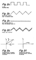
- the output voltages from each of the two detectors 90 and 92 consist of a combination of two frequencies: (1) a triangular wave of approximately 1 Hz and a few millivolts in amplitude (Fig.2A), which is due to the 1 Hz square wave (Fig. 2A) modulation of the IR source 16, the triangular-shaped output being caused by the integration effect from the very slow temperature change of the source in response to the square wave change in current through the IR source 16, and (2) a sine wave comprising about 10 to 15 microvolts peak-to-peak of offset (both channels) (Fig.
- Fig.2C The 600 Hz AC signals (Fig.2C) are detectable using synchronous detectors 102 and 104 (sometimes called “lock-in amplifiers"), referenced to the AC output of the pressure transducer 26.
- the lock-in amplifiers 92 and 94 are available from E.G. & G, Princeton Applied Research Division, Princeton, N.J., Model No. 5210.
- Derivation of CO concentration is accomplished by vectorially subtracting the offset voltage obtained from the reference channel 84 (the output due to CO being absorbed by the CO cell) from the output obtained from the measurement channel 86.
- the vector V, (fig.2e) represents the output signal received from the measurement channel 86, which is the vector sum of offset vector V os and absorption signal vector V G .
- Vector rotation frequency is equal to the pressure modulation frequency.
- the output signal from the reference channel 84 (fig.2f) contains only the offset signal V os .
- the algorithm, Appendix A calculates V G by subtracting vector V os from vector V i .
- the measurement and reference channels 86, 84 have slightly different sensitivities due to optical path and electronic assymetries. This produces slightly different values for Vos from each channel.
- a sample gas is introduced into the analyzer which contains no carbon monoxide, so that the output of each channel will be due only to the offset component vector, V os .
- a cross-channel normalization constant may then be determined. In this manner, the offset vector V os determined from the reference channel 84 may be multiplied by the appropriate constant such that it will exactly cancel the offset vector appearing in the measurement channel output.
- Variations in DC pressure inside the sample chamber, modulation pressure, sample humidity, and analyzer temperature are measured and used to correct the final gas concentration reading.
- Variations in IR source intensity are detected by modulating the IR source intensity at a frequency much lower than the pressure modulation frequency. Source intensity variations may then be detected and electronically separated from the IR absorption signals at the pressure modulation frequency by an IR modulation detector (low pass filter) 106. The intensity variation information is used to provide a further correction to the gas concentration output. All necessary parameters being connected to computer 110.
- Appendix A A summary of all of the calculations required, including those used at the time of initial calibration and those used during each measurement, is given in Appendix A.
- the "Summary of Calculations" of Appendix A is the equivalent of a flow chart for the algorithm.
- CO is the gas being analyzed but other gases may be similarly analyzed with the gas in the reference cell changed accordingly.
- the optical filter matches the IR energy absorption band for CO but if other gases are analyzed having different IR absorption bands of radiant energy are used, the filter will be changed accordingly.
- pump pressure modulator
- Speaker is used herein interchangeably
- IR energy and radiant energy are used herein interchangeably.
Landscapes
- Physics & Mathematics (AREA)
- Spectroscopy & Molecular Physics (AREA)
- Health & Medical Sciences (AREA)
- Life Sciences & Earth Sciences (AREA)
- Chemical & Material Sciences (AREA)
- Analytical Chemistry (AREA)
- Biochemistry (AREA)
- General Health & Medical Sciences (AREA)
- General Physics & Mathematics (AREA)
- Immunology (AREA)
- Pathology (AREA)
- Investigating Or Analysing Materials By Optical Means (AREA)
Applications Claiming Priority (2)
| Application Number | Priority Date | Filing Date | Title |
|---|---|---|---|
| US07/324,069 US4975582A (en) | 1989-03-16 | 1989-03-16 | Pressure-modulated infrared gas analyzer and method |
| US324069 | 1989-03-16 |
Publications (3)
| Publication Number | Publication Date |
|---|---|
| EP0387684A2 true EP0387684A2 (fr) | 1990-09-19 |
| EP0387684A3 EP0387684A3 (fr) | 1991-07-24 |
| EP0387684B1 EP0387684B1 (fr) | 1995-05-24 |
Family
ID=23261927
Family Applications (1)
| Application Number | Title | Priority Date | Filing Date |
|---|---|---|---|
| EP90104364A Expired - Lifetime EP0387684B1 (fr) | 1989-03-16 | 1990-03-07 | Appareil et méthode pour analyser, à l'aide de rayonnement infra-rouge, des gaz dont la pression est modulée |
Country Status (6)
| Country | Link |
|---|---|
| US (1) | US4975582A (fr) |
| EP (1) | EP0387684B1 (fr) |
| JP (1) | JPH03202755A (fr) |
| KR (1) | KR0160294B1 (fr) |
| CA (1) | CA2010868A1 (fr) |
| DE (1) | DE69019569T2 (fr) |
Cited By (8)
| Publication number | Priority date | Publication date | Assignee | Title |
|---|---|---|---|---|
| DE4316196A1 (de) * | 1993-05-14 | 1993-10-14 | Guenter Dr Vos | Verfahren und Vorrichtung zur Gasanalyse |
| DE19649343A1 (de) * | 1996-11-28 | 1998-06-10 | Fraunhofer Ges Forschung | Vorrichtung zur photometrischen Untersuchung eines gasförmigen Probenmediums |
| EP0994340A1 (fr) * | 1998-10-16 | 2000-04-19 | L'air Liquide, Societe Anonyme Pour L'etude Et L'exploitation Des Procedes Georges Claude | Procédé et dispositif de mesure de la quantité d'impuretés dans un échantillon de gaz à analyser |
| DE19911260A1 (de) * | 1999-03-13 | 2000-09-14 | Leybold Vakuum Gmbh | Infrarot-Gasanalysator und Verfahren zum Betrieb dieses Analysators |
| DE4302385C2 (de) * | 1992-01-30 | 2003-10-16 | Vaisala Oy Helsinki | Verfahren zur Bestimmung der Konzentration einer Gaskomponente in einer Gasprobe |
| US7257986B2 (en) | 2004-04-20 | 2007-08-21 | Dräger Safety AG & Co. KGaA | Gas sensor with increased measuring sensitivity |
| WO2010024756A1 (fr) * | 2008-08-28 | 2010-03-04 | Senseair Ab | Système adapté à l’analyse spectrale de petites concentrations de gaz |
| CN115656087A (zh) * | 2022-11-09 | 2023-01-31 | 浙江浙大鸣泉科技有限公司 | 一种具有检测气体间浓度补偿方法的八通道ndir光学平台 |
Families Citing this family (9)
| Publication number | Priority date | Publication date | Assignee | Title |
|---|---|---|---|---|
| US5449912A (en) * | 1994-06-15 | 1995-09-12 | Modern Controls, Inc. | Measurement cell for water vapor sensor |
| US5495875A (en) * | 1994-12-01 | 1996-03-05 | Scott Specialty Gases, Inc. | System for continuous blending of a liquid into a gas |
| US5977546A (en) * | 1997-05-13 | 1999-11-02 | Carlson; Lee Richard | Self normalizing radiant energy monitor and apparatus for gain independent material quantity measurements |
| US6138674A (en) * | 1997-10-16 | 2000-10-31 | Datex-Ohmeda, Inc. | Active temperature and humidity compensator for anesthesia monitoring systems |
| TWI236531B (en) * | 2003-10-06 | 2005-07-21 | King Can Industry Corp | Gas concentration detector and its method |
| DE102007020596A1 (de) * | 2007-05-02 | 2008-11-06 | Siemens Ag | Detektoranordnung für einen nichtdispersiven Infrarot-Gasanalysator |
| SE0802069A1 (sv) * | 2008-09-30 | 2010-03-31 | Senseair Ab | Ett för en spektralanalys av höga gaskoncentrationer anpassat arrangemang |
| DE102009021829A1 (de) * | 2009-05-19 | 2010-11-25 | Siemens Aktiengesellschaft | NDIR-Zweistrahl-Gasanalysator und Verfahren zur Bestimmung der Konzentration einer Messgaskomponente in einem Gasgemisch mittels eines solchen Gasanalysators |
| JP7473170B2 (ja) * | 2020-04-06 | 2024-04-23 | 光明理化学工業株式会社 | ガス濃度測定装置 |
Family Cites Families (9)
| Publication number | Priority date | Publication date | Assignee | Title |
|---|---|---|---|---|
| US3005097A (en) * | 1956-08-18 | 1961-10-17 | Hartmann & Braun Ag | Method and apparatus for the analysis by radiation of mixtures of substances |
| US4063094A (en) * | 1966-10-17 | 1977-12-13 | American Standard Inc. | Gas analyzer |
| US3728540A (en) * | 1971-08-27 | 1973-04-17 | Tetra Tech | Pressure-modulated multiple gas analyzer |
| US3902068A (en) * | 1974-04-10 | 1975-08-26 | Modern Controls Inc | Method and apparatus for measuring the gas transmission through packaging materials |
| US4163899A (en) * | 1977-11-30 | 1979-08-07 | Andros, Inc. | Method and apparatus for gas analysis |
| US4188534A (en) * | 1978-04-20 | 1980-02-12 | Fuji Electric Co., Ltd. | Infrared gas analyzer |
| DE2952464C2 (de) * | 1979-12-27 | 1986-03-27 | Siemens AG, 1000 Berlin und 8000 München | Nichtdispersiver Infrarot-Gasanalysator |
| GB2110818B (en) * | 1981-11-14 | 1985-05-15 | Ferranti Ltd | Non-dispersive gas analyser |
| US4902896A (en) * | 1987-05-08 | 1990-02-20 | Mine Safety Appliances Company | Infrared fluid analyzer |
-
1989
- 1989-03-16 US US07/324,069 patent/US4975582A/en not_active Expired - Fee Related
-
1990
- 1990-02-23 CA CA002010868A patent/CA2010868A1/fr not_active Abandoned
- 1990-03-07 DE DE69019569T patent/DE69019569T2/de not_active Expired - Fee Related
- 1990-03-07 EP EP90104364A patent/EP0387684B1/fr not_active Expired - Lifetime
- 1990-03-13 KR KR1019900003347A patent/KR0160294B1/ko not_active Expired - Fee Related
- 1990-03-16 JP JP2064484A patent/JPH03202755A/ja active Pending
Cited By (12)
| Publication number | Priority date | Publication date | Assignee | Title |
|---|---|---|---|---|
| DE4302385C2 (de) * | 1992-01-30 | 2003-10-16 | Vaisala Oy Helsinki | Verfahren zur Bestimmung der Konzentration einer Gaskomponente in einer Gasprobe |
| DE4316196A1 (de) * | 1993-05-14 | 1993-10-14 | Guenter Dr Vos | Verfahren und Vorrichtung zur Gasanalyse |
| DE19649343A1 (de) * | 1996-11-28 | 1998-06-10 | Fraunhofer Ges Forschung | Vorrichtung zur photometrischen Untersuchung eines gasförmigen Probenmediums |
| EP0994340A1 (fr) * | 1998-10-16 | 2000-04-19 | L'air Liquide, Societe Anonyme Pour L'etude Et L'exploitation Des Procedes Georges Claude | Procédé et dispositif de mesure de la quantité d'impuretés dans un échantillon de gaz à analyser |
| FR2784747A1 (fr) * | 1998-10-16 | 2000-04-21 | Air Liquide | Procede et dispositif de mesure de la quantite d'impuretes dans un echantillon de gaz a analyser |
| US6341521B1 (en) | 1998-10-16 | 2002-01-29 | L'air Liquide, Societe Anonyme Pour L'etude Et L'exploitation Des Procedes Georges Claude | Process and device for measuring the amount of impurities in a gas sample to be analyzed |
| DE19911260A1 (de) * | 1999-03-13 | 2000-09-14 | Leybold Vakuum Gmbh | Infrarot-Gasanalysator und Verfahren zum Betrieb dieses Analysators |
| US6635875B1 (en) | 1999-03-13 | 2003-10-21 | Inficon Gmbh | Infrared gas analyzer and method for operating said analyzer |
| US7257986B2 (en) | 2004-04-20 | 2007-08-21 | Dräger Safety AG & Co. KGaA | Gas sensor with increased measuring sensitivity |
| WO2010024756A1 (fr) * | 2008-08-28 | 2010-03-04 | Senseair Ab | Système adapté à l’analyse spectrale de petites concentrations de gaz |
| CN115656087A (zh) * | 2022-11-09 | 2023-01-31 | 浙江浙大鸣泉科技有限公司 | 一种具有检测气体间浓度补偿方法的八通道ndir光学平台 |
| CN115656087B (zh) * | 2022-11-09 | 2023-08-22 | 浙江浙大鸣泉科技有限公司 | 一种具有检测气体间浓度补偿方法的八通道ndir光学平台 |
Also Published As
| Publication number | Publication date |
|---|---|
| KR900014877A (ko) | 1990-10-25 |
| US4975582A (en) | 1990-12-04 |
| DE69019569D1 (de) | 1995-06-29 |
| DE69019569T2 (de) | 1995-09-28 |
| JPH03202755A (ja) | 1991-09-04 |
| KR0160294B1 (ko) | 1999-05-01 |
| EP0387684A3 (fr) | 1991-07-24 |
| CA2010868A1 (fr) | 1990-09-16 |
| EP0387684B1 (fr) | 1995-05-24 |
Similar Documents
| Publication | Publication Date | Title |
|---|---|---|
| US4975582A (en) | Pressure-modulated infrared gas analyzer and method | |
| US6044332A (en) | Surface acoustic wave harmonic analysis | |
| CA1254281A (fr) | Methode et appareil de detection et de mesure des concentrations de gaz | |
| EP2496136B1 (fr) | Appareil pour mesurer un niveau d'un gaz spécifique dans l'air expiré | |
| US8594507B2 (en) | Method and apparatus for measuring gas concentrations | |
| US4902896A (en) | Infrared fluid analyzer | |
| EP0685728A1 (fr) | Appareil et méthode d'analyse photoacoustique | |
| US5390539A (en) | Device for measuring the permeability of a membrane to water vapor | |
| US8689607B2 (en) | Apparatus and method of photoacoustic sensor signal acquisition | |
| US4594004A (en) | Continuous particulate-measuring apparatus using an optoacoustic effect | |
| US4200399A (en) | Resonant optoacoustic spectroscopy apparatus | |
| CN102759508B (zh) | 具有自适应操作频率的光声传感器 | |
| JPH03223669A (ja) | 超音波ガス測定器 | |
| US4050823A (en) | Apparatus for continuously measuring the CO2 content in breathing gases | |
| US4163899A (en) | Method and apparatus for gas analysis | |
| US4355233A (en) | Method and apparatus for negating measurement effects of interferent gases in non-dispersive infrared analyzers | |
| US20020017124A1 (en) | Apparatus and method for the determination of the relative proportions of gases | |
| US20120272717A1 (en) | Photoacoustic Detector with Background Signal Correction | |
| JP3024904B2 (ja) | 光学式ガス分析計 | |
| JPH0843303A (ja) | 濃度測定装置 | |
| JPS56154630A (en) | Detecting method of abnormal vibration | |
| EP0015068B2 (fr) | Analyseurs infrarouges non dispersifs | |
| DK156282B (da) | Fototermisk fremgangsmaade til studium af lysabsorptionen hos en proevesubstans | |
| GB1493729A (en) | Vapour concentration monitors | |
| JPS6013457B2 (ja) | 光音響分析器 |
Legal Events
| Date | Code | Title | Description |
|---|---|---|---|
| PUAI | Public reference made under article 153(3) epc to a published international application that has entered the european phase |
Free format text: ORIGINAL CODE: 0009012 |
|
| AK | Designated contracting states |
Kind code of ref document: A2 Designated state(s): DE FR GB IT NL |
|
| PUAL | Search report despatched |
Free format text: ORIGINAL CODE: 0009013 |
|
| AK | Designated contracting states |
Kind code of ref document: A3 Designated state(s): DE FR GB IT NL |
|
| 17P | Request for examination filed |
Effective date: 19920124 |
|
| 17Q | First examination report despatched |
Effective date: 19940118 |
|
| GRAA | (expected) grant |
Free format text: ORIGINAL CODE: 0009210 |
|
| AK | Designated contracting states |
Kind code of ref document: B1 Designated state(s): DE FR GB IT NL |
|
| ITF | It: translation for a ep patent filed | ||
| REF | Corresponds to: |
Ref document number: 69019569 Country of ref document: DE Date of ref document: 19950629 |
|
| ET | Fr: translation filed | ||
| PGFP | Annual fee paid to national office [announced via postgrant information from national office to epo] |
Ref country code: FR Payment date: 19960221 Year of fee payment: 7 |
|
| PGFP | Annual fee paid to national office [announced via postgrant information from national office to epo] |
Ref country code: NL Payment date: 19960223 Year of fee payment: 7 Ref country code: DE Payment date: 19960223 Year of fee payment: 7 |
|
| PGFP | Annual fee paid to national office [announced via postgrant information from national office to epo] |
Ref country code: GB Payment date: 19960228 Year of fee payment: 7 |
|
| PLBE | No opposition filed within time limit |
Free format text: ORIGINAL CODE: 0009261 |
|
| STAA | Information on the status of an ep patent application or granted ep patent |
Free format text: STATUS: NO OPPOSITION FILED WITHIN TIME LIMIT |
|
| 26N | No opposition filed | ||
| PG25 | Lapsed in a contracting state [announced via postgrant information from national office to epo] |
Ref country code: GB Effective date: 19970307 |
|
| PG25 | Lapsed in a contracting state [announced via postgrant information from national office to epo] |
Ref country code: NL Effective date: 19971001 |
|
| GBPC | Gb: european patent ceased through non-payment of renewal fee |
Effective date: 19970307 |
|
| PG25 | Lapsed in a contracting state [announced via postgrant information from national office to epo] |
Ref country code: FR Free format text: LAPSE BECAUSE OF NON-PAYMENT OF DUE FEES Effective date: 19971128 |
|
| NLV4 | Nl: lapsed or anulled due to non-payment of the annual fee |
Effective date: 19971001 |
|
| PG25 | Lapsed in a contracting state [announced via postgrant information from national office to epo] |
Ref country code: DE Effective date: 19971202 |
|
| REG | Reference to a national code |
Ref country code: FR Ref legal event code: ST |
|
| PG25 | Lapsed in a contracting state [announced via postgrant information from national office to epo] |
Ref country code: IT Free format text: LAPSE BECAUSE OF NON-PAYMENT OF DUE FEES;WARNING: LAPSES OF ITALIAN PATENTS WITH EFFECTIVE DATE BEFORE 2007 MAY HAVE OCCURRED AT ANY TIME BEFORE 2007. THE CORRECT EFFECTIVE DATE MAY BE DIFFERENT FROM THE ONE RECORDED. Effective date: 20050307 |