EP0387703A2 - Contrôle de brûleur pour installations de chauffage - Google Patents
Contrôle de brûleur pour installations de chauffage Download PDFInfo
- Publication number
- EP0387703A2 EP0387703A2 EP90104426A EP90104426A EP0387703A2 EP 0387703 A2 EP0387703 A2 EP 0387703A2 EP 90104426 A EP90104426 A EP 90104426A EP 90104426 A EP90104426 A EP 90104426A EP 0387703 A2 EP0387703 A2 EP 0387703A2
- Authority
- EP
- European Patent Office
- Prior art keywords
- burner
- time
- pause
- switched
- pause time
- Prior art date
- Legal status (The legal status is an assumption and is not a legal conclusion. Google has not performed a legal analysis and makes no representation as to the accuracy of the status listed.)
- Granted
Links
Images


Classifications
-
- F—MECHANICAL ENGINEERING; LIGHTING; HEATING; WEAPONS; BLASTING
- F23—COMBUSTION APPARATUS; COMBUSTION PROCESSES
- F23N—REGULATING OR CONTROLLING COMBUSTION
- F23N1/00—Regulating fuel supply
-
- F—MECHANICAL ENGINEERING; LIGHTING; HEATING; WEAPONS; BLASTING
- F23—COMBUSTION APPARATUS; COMBUSTION PROCESSES
- F23N—REGULATING OR CONTROLLING COMBUSTION
- F23N1/00—Regulating fuel supply
- F23N1/002—Regulating fuel supply using electronic means
-
- F—MECHANICAL ENGINEERING; LIGHTING; HEATING; WEAPONS; BLASTING
- F23—COMBUSTION APPARATUS; COMBUSTION PROCESSES
- F23N—REGULATING OR CONTROLLING COMBUSTION
- F23N5/00—Systems for controlling combustion
- F23N5/20—Systems for controlling combustion with a time program acting through electrical means, e.g. using time-delay relays
- F23N5/203—Systems for controlling combustion with a time program acting through electrical means, e.g. using time-delay relays using electronic means
-
- F—MECHANICAL ENGINEERING; LIGHTING; HEATING; WEAPONS; BLASTING
- F23—COMBUSTION APPARATUS; COMBUSTION PROCESSES
- F23N—REGULATING OR CONTROLLING COMBUSTION
- F23N1/00—Regulating fuel supply
- F23N1/08—Regulating fuel supply conjointly with another medium, e.g. boiler water
-
- F—MECHANICAL ENGINEERING; LIGHTING; HEATING; WEAPONS; BLASTING
- F23—COMBUSTION APPARATUS; COMBUSTION PROCESSES
- F23N—REGULATING OR CONTROLLING COMBUSTION
- F23N2223/00—Signal processing; Details thereof
- F23N2223/22—Timing network
-
- F—MECHANICAL ENGINEERING; LIGHTING; HEATING; WEAPONS; BLASTING
- F23—COMBUSTION APPARATUS; COMBUSTION PROCESSES
- F23N—REGULATING OR CONTROLLING COMBUSTION
- F23N2227/00—Ignition or checking
- F23N2227/10—Sequential burner running
Definitions
- the new process has the task of reducing the number of starts in order to protect the burner and make the system more environmentally friendly.
- Such an oppositely variable pause time can be easily achieved by programming a maximum pause time that is a constant multiple of the burner's operating time is shortened. If the burner is switched on for a longer period of time, this even reduces the pause time to '0', which means that the burner's full heating output can be used.
- This bridging contact can also be a thermostat contact, which falls below a minimum temperature of z. B. 16 ° C closes.
- Figure 1 shows the functional diagram of a previous temperature control between two fixed temperatures T1 and T. As soon as the room temperature drops below the value T1, the burner or the heater is switched on until the temperature T is reached. Then the thermostat switches off and so on.
- the switch-on times can be very short and numerous.
- Figure 2 is a corresponding functional diagram for a device according to the invention.
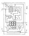
- Figure 3 shows the schematic circuit diagram of a break control according to the invention.
- the burner (1) is switched on by the thermostat contact (2) via the normally closed break contact (4).
- the time control (6) receives the information via line (7) that the burner (1) is switched on.
- the control ends (6) the time measurement of how long the burner (1) was switched on.
- the time control (6) actuates the break contact (4) via the relay (5), opens it and thus prevents the burner (1) from being switched on again.
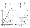
- This function can be read from FIG. 4, the time t in minutes being indicated on the horizontal axis and the pause time T p likewise being indicated in minutes on the vertical axis.
- FIG. 4 shows the course of the burner's switch-on time and the pause time T p derived therefrom.
- the pause time (cycle time) is also reduced by one minute of the pause time.
- the point (11) in FIG. 4 at the intersection of the straight lines T p and T Br means that in this example the pause time T p has shrunk to '0' after twenty minutes of burning time.
- FIG. 6 schematically shows the structure of a digital time control which is able to implement the pause circuit shown in FIG. 1.
- Such a timing can, for. B. from a digital time pulse generator (16) and a pulse counter (17).
- the time pulse generator (16) is, for. B. designed so that you can select time pulses after 60,45,30 or 15 seconds to feed them to the pulse counter (17).
- the time pulse generator (16) is reset to '0' after the maximum time of 60 seconds.
- the maximum number of pulses at which the breaks can be ended and the burner can be switched on again by the thermostat (2) is set on the pulse counter (17) using the setting button (8).
- the number of maximum pulses can be read from the display (19).
- the current number of pulses which have elapsed in the respective cycle can also be read on a second display (18).
- the relay (20) receives voltage via line (7) and switches the contact (22), which has the task of switching the cycle times, to line (25) and thus via the selector switch (9) to one of the shortened cycle times, eg as shown to a 30-second cycle, ie twice as fast as the basic cycle time 60 seconds.
- the relay (20) no longer receives any voltage. It falls off and the contact (22) connects the pulse counter (17) via line (24) and (26) with the basic cycle time of 60 seconds. At the same time, the relay (5) picks up and opens the break contact (4).
- the pulse counter (17) from the clock generator (16) is supplied with pulses every 60 seconds until the number of pulses shown on the display (19) (in this example '40') is reached. At this maximum number of pulses, the pulse counter (17) is also set to '0', the relay (5) is de-energized and the break contact (4) closes.
- the burner (1) can only start operating again now, even if the thermostat (2) had previously closed.
- FIG. 5 shows the course of a control curve as can be achieved with the circuit of FIG. 6.
- Time t is plotted again horizontally, and the number of corresponding time pulses plotted vertically. In this example, too, a preselected maximum number of pulses of 40 pulses is assumed.
- the duplication constant K 1 is also retained. This corresponds to a pulse sequence twice as fast during the burner's switch-on time, i.e. 1 pulse in 30 seconds.
- FIG. 5 shows a steep increase during this burner running time, which is assumed to be 15 minutes, to 30 pulses corresponding to line 26.
- the time counting according to line 27 runs slowly with one pulse per minute during the remaining time (pause time T p ) until the preselected maximum pause time Pm is reached at 40 pulses.
- FIG. 5 also shows, for example, the possibility of driving a variable-capacity two-stage burner. e.g. B. full and half power.
- the pulse counter (17) of the time control (6) has a further setting option.
- a number of pulses (31) can be set, at which the control checks whether the burner is still switched on, according to item 29 in FIG. 5. If this is not the case, this means that less than half Burner power is required in the control cycle and the time control (6) gives the command to switch over to half the power via the command line (32) (see circuit diagram in FIG. 6).
- the burner receives the command to run with higher power via the command line (32).
Landscapes
- Engineering & Computer Science (AREA)
- Chemical & Material Sciences (AREA)
- Combustion & Propulsion (AREA)
- Mechanical Engineering (AREA)
- General Engineering & Computer Science (AREA)
- Control Of Combustion (AREA)
- Regulation And Control Of Combustion (AREA)
- Control Of Steam Boilers And Waste-Gas Boilers (AREA)
- Sorption Type Refrigeration Machines (AREA)
Applications Claiming Priority (2)
| Application Number | Priority Date | Filing Date | Title |
|---|---|---|---|
| DE3908136A DE3908136A1 (de) | 1989-03-13 | 1989-03-13 | Regelung fuer brenner von heizanlagen |
| DE3908136 | 1989-03-13 |
Publications (3)
| Publication Number | Publication Date |
|---|---|
| EP0387703A2 true EP0387703A2 (fr) | 1990-09-19 |
| EP0387703A3 EP0387703A3 (fr) | 1991-07-03 |
| EP0387703B1 EP0387703B1 (fr) | 1995-08-02 |
Family
ID=6376239
Family Applications (1)
| Application Number | Title | Priority Date | Filing Date |
|---|---|---|---|
| EP90104426A Expired - Lifetime EP0387703B1 (fr) | 1989-03-13 | 1990-03-08 | Contrôle de brûleur pour installations de chauffage |
Country Status (5)
| Country | Link |
|---|---|
| US (1) | US5135162A (fr) |
| EP (1) | EP0387703B1 (fr) |
| JP (1) | JPH02290418A (fr) |
| AT (1) | ATE125929T1 (fr) |
| DE (2) | DE3908136A1 (fr) |
Cited By (3)
| Publication number | Priority date | Publication date | Assignee | Title |
|---|---|---|---|---|
| DE19507247A1 (de) * | 1995-03-02 | 1996-09-05 | Baunach Hans Georg | Verfahren und Vorrichtung zur hydraulisch optimierten Regelung der Vorlauftemepratur |
| WO2011104505A3 (fr) * | 2010-02-25 | 2012-10-11 | Contec Heat Controls Ltd | Unités de commande pour unités d'alimentation en chaleur |
| IT202000016483A1 (it) * | 2020-07-08 | 2022-01-08 | Alperia Bartucci S P A | Metodo di controllo di mezzi di riscaldamento e sistema di riscaldamento comprendente detti mezzi di riscaldamento |
Families Citing this family (11)
| Publication number | Priority date | Publication date | Assignee | Title |
|---|---|---|---|---|
| AT405449B (de) * | 1992-09-21 | 1999-08-25 | Vaillant Gmbh | Verfahren zum steuern einer heizungsanlage und vorrichtung zur durchführung des verfahrens |
| US5372120A (en) * | 1993-07-23 | 1994-12-13 | Swilik, Jr.; Robert C. | Safety circuit for furnace |
| CH692757A5 (de) * | 1994-07-16 | 2002-10-15 | Vaillant Gmbh | Verfahren zum Steuern einer Heizungsanlage. |
| DE19744393A1 (de) * | 1997-10-08 | 1999-04-29 | Sparsames Heizen Mbh Ges | Verfahren zum Betreiben einer Kesselanlage mit verzögertem Brennereinschaltverhalten, Vorrichtung zum Verzögern des Brennerstarts und Kesselanlage mit einer Vorrichtung zum Verzögern des Brennerstarts |
| DE19807324C2 (de) * | 1998-02-20 | 2002-08-29 | Viessmann Werke Kg | Steuerungsverfahren und Steuerungsvorrichtung für ein Heizsystem |
| AT412504B (de) * | 1999-11-03 | 2005-03-25 | Vaillant Gmbh | Verfahren zum laden eines speichers einer heizungsanlage |
| DE29921359U1 (de) | 1999-12-03 | 2000-04-13 | MOI Elektronik AG, 66780 Rehlingen-Siersburg | Vorrichtung zur Steuerung einer brennerbetriebenen Heizungsanlage |
| DE19963974C2 (de) * | 1999-12-31 | 2002-11-14 | Bosch Gmbh Robert | Gasbrenner |
| DE102006014633B4 (de) * | 2006-03-29 | 2013-02-21 | Ryll-Tech Gmbh | Heizbrenner |
| FR2938049B1 (fr) * | 2008-10-31 | 2012-11-30 | Filtres Equipements | Rechauffeur de fluide combustible. |
| US20100300377A1 (en) * | 2010-08-11 | 2010-12-02 | Buescher Thomas P | Water heater apparatus with differential control |
Family Cites Families (8)
| Publication number | Priority date | Publication date | Assignee | Title |
|---|---|---|---|---|
| US2477728A (en) * | 1946-12-12 | 1949-08-02 | Warren Webster & Co | Automatic temperature control system |
| US4196356A (en) * | 1978-01-27 | 1980-04-01 | Honeywell Inc. | Expanded time constant condition control system |
| DE3232795A1 (de) * | 1982-09-03 | 1984-03-08 | Dreizler, Walter, Dipl.-Ing. (FH), 7000 Stuttgart | Regeleinrichtung mit selbsttaetiger brennerlaufzeit-steuerung von brennern |
| GB8318452D0 (en) * | 1983-07-07 | 1983-08-10 | Esg Controls Ltd | Boiler cycling controller |
| DE3345705A1 (de) * | 1983-12-17 | 1985-06-27 | Walter Dipl.-Ing. 7000 Stuttgart Dreizler | Vorrichtung zur brennersteuerung |
| DE3524230A1 (de) * | 1985-07-06 | 1987-01-08 | Honeywell Bv | Einrichtung zur regelung der raumtemperatur |
| US4850310A (en) * | 1986-06-30 | 1989-07-25 | Harry Wildgen | Boiler control having reduced number of boiler sequences for a given load |
| DE3829677C2 (de) * | 1988-09-01 | 1997-12-11 | Lve Verfahrenselektronik Gmbh | Verfahren und Anordnung zur Regelung von pulssteuerbaren Brennern in einer wärmetechnischen Anlage |
-
1989
- 1989-03-13 DE DE3908136A patent/DE3908136A1/de not_active Withdrawn
-
1990
- 1990-03-07 US US07/489,567 patent/US5135162A/en not_active Expired - Fee Related
- 1990-03-08 DE DE59009455T patent/DE59009455D1/de not_active Expired - Fee Related
- 1990-03-08 EP EP90104426A patent/EP0387703B1/fr not_active Expired - Lifetime
- 1990-03-08 AT AT90104426T patent/ATE125929T1/de not_active IP Right Cessation
- 1990-03-13 JP JP2062450A patent/JPH02290418A/ja active Pending
Cited By (3)
| Publication number | Priority date | Publication date | Assignee | Title |
|---|---|---|---|---|
| DE19507247A1 (de) * | 1995-03-02 | 1996-09-05 | Baunach Hans Georg | Verfahren und Vorrichtung zur hydraulisch optimierten Regelung der Vorlauftemepratur |
| WO2011104505A3 (fr) * | 2010-02-25 | 2012-10-11 | Contec Heat Controls Ltd | Unités de commande pour unités d'alimentation en chaleur |
| IT202000016483A1 (it) * | 2020-07-08 | 2022-01-08 | Alperia Bartucci S P A | Metodo di controllo di mezzi di riscaldamento e sistema di riscaldamento comprendente detti mezzi di riscaldamento |
Also Published As
| Publication number | Publication date |
|---|---|
| JPH02290418A (ja) | 1990-11-30 |
| DE3908136A1 (de) | 1990-09-20 |
| EP0387703B1 (fr) | 1995-08-02 |
| ATE125929T1 (de) | 1995-08-15 |
| EP0387703A3 (fr) | 1991-07-03 |
| DE59009455D1 (de) | 1995-09-07 |
| US5135162A (en) | 1992-08-04 |
Similar Documents
| Publication | Publication Date | Title |
|---|---|---|
| EP0387703B1 (fr) | Contrôle de brûleur pour installations de chauffage | |
| DE3517902C2 (fr) | ||
| DE4239929C2 (de) | Verfahren zum automatischen Einstellen einer Heizungsanlage auf Sommer- oder Winterbetrieb | |
| DE2753536A1 (de) | Steuerschaltung fuer eine zentral- heizungsanlage | |
| DE3117789A1 (de) | Verfahren zum regeln bzw. steuern einer heizungsanlage | |
| DE3525315A1 (de) | Verfahren zum steuern von einzelspeichern | |
| EP0273064B1 (fr) | Appareil de réglage et de commande électrique pour une installation délivrant de l'énergie à des radiateurs spacialement répartis, chauffe-eau ou similaire | |
| DE2306070A1 (de) | Steuervorrichtung fuer die aufheizung von speicherheizgeraeten | |
| DE2943931A1 (de) | Heizungsregelung mit begrenzung der verbrauchten leistung | |
| AT406216B (de) | Vorrichtung zur programmierung eines heizgerätes | |
| EP0530727B1 (fr) | Appareil de chauffage à accumulation | |
| DE1454444A1 (de) | Heizungsregelung | |
| DE3109670A1 (de) | "verfahren zum regeln von heizkesseln mit mehrstufigen brennern und regeleinrichtung zur ausfuehrung des verfahrens" | |
| DE676876C (de) | Anordnung zur selbsttaetigen Abschaltung elektrischer Stromverbraucher nach Aufnahme einer bestimmten Energiemenge | |
| DE1565197C3 (de) | Steuergerät zur witterungs- und zeitabhängigen Verschiebung des Ladebeginns von elektrischen Wärmespeichern | |
| DE1790009A1 (de) | Vorrichtung zur selbsttaetigen Regelung der Heizleistung elektrischer Mehrstufen-Direktheizungen | |
| DE1813644B2 (de) | Temperaturbegrenzer mit anzeige eines defektes eines temperaturreglers | |
| DE1465055A1 (de) | Anordnung zur Fernsteuerung der Aufladung mindestens einer elektrischen Waermespeicher-Heizeinrichtung | |
| DE2746454A1 (de) | Steuerungsvorrichtung fuer einen elektrowaermespeicher | |
| DE2428501A1 (de) | Waehlerzentrale mit leistungsregelung fuer oel- oder gasbrenner, vorzugsweise kontinuierlich geregelte (modulierende) brenner | |
| DE1565636B2 (de) | Verfahren zum Verschieben des Ladebeginn-Zeitpunktes bei Elektro-Wärmespei ehern | |
| CH389812A (de) | Steuerschaltung für einen Flammenwächter | |
| DE3433132A1 (de) | Einrichtung fuer zeitabhaengig arbeitende aufladesteuerungen von elektrospeicherheizungen | |
| DE1565687A1 (de) | Verfahren zur Steuerung von Wärmespeicheröfen | |
| DE1815102A1 (de) | Selbsttaetige mechanische Regelvorrichtung |
Legal Events
| Date | Code | Title | Description |
|---|---|---|---|
| PUAI | Public reference made under article 153(3) epc to a published international application that has entered the european phase |
Free format text: ORIGINAL CODE: 0009012 |
|
| AK | Designated contracting states |
Kind code of ref document: A2 Designated state(s): AT CH DE FR GB LI SE |
|
| PUAL | Search report despatched |
Free format text: ORIGINAL CODE: 0009013 |
|
| AK | Designated contracting states |
Kind code of ref document: A3 Designated state(s): AT CH DE FR GB LI SE |
|
| 17P | Request for examination filed |
Effective date: 19911016 |
|
| 17Q | First examination report despatched |
Effective date: 19931125 |
|
| GRAA | (expected) grant |
Free format text: ORIGINAL CODE: 0009210 |
|
| AK | Designated contracting states |
Kind code of ref document: B1 Designated state(s): AT CH DE FR GB LI SE |
|
| PG25 | Lapsed in a contracting state [announced via postgrant information from national office to epo] |
Ref country code: GB Effective date: 19950802 Ref country code: FR Effective date: 19950802 |
|
| REF | Corresponds to: |
Ref document number: 125929 Country of ref document: AT Date of ref document: 19950815 Kind code of ref document: T |
|
| REF | Corresponds to: |
Ref document number: 59009455 Country of ref document: DE Date of ref document: 19950907 |
|
| PG25 | Lapsed in a contracting state [announced via postgrant information from national office to epo] |
Ref country code: SE Effective date: 19951102 |
|
| EN | Fr: translation not filed | ||
| GBV | Gb: ep patent (uk) treated as always having been void in accordance with gb section 77(7)/1977 [no translation filed] |
Effective date: 19950802 |
|
| PG25 | Lapsed in a contracting state [announced via postgrant information from national office to epo] |
Ref country code: AT Effective date: 19960308 |
|
| PG25 | Lapsed in a contracting state [announced via postgrant information from national office to epo] |
Ref country code: LI Effective date: 19960331 Ref country code: CH Effective date: 19960331 |
|
| PLBQ | Unpublished change to opponent data |
Free format text: ORIGINAL CODE: EPIDOS OPPO |
|
| PLBI | Opposition filed |
Free format text: ORIGINAL CODE: 0009260 |
|
| PLBF | Reply of patent proprietor to notice(s) of opposition |
Free format text: ORIGINAL CODE: EPIDOS OBSO |
|
| 26 | Opposition filed |
Opponent name: JOH. VAILLANT GMBH U. CO. Effective date: 19960430 |
|
| PLBF | Reply of patent proprietor to notice(s) of opposition |
Free format text: ORIGINAL CODE: EPIDOS OBSO |
|
| REG | Reference to a national code |
Ref country code: CH Ref legal event code: PL |
|
| PLBO | Opposition rejected |
Free format text: ORIGINAL CODE: EPIDOS REJO |
|
| PLBN | Opposition rejected |
Free format text: ORIGINAL CODE: 0009273 |
|
| STAA | Information on the status of an ep patent application or granted ep patent |
Free format text: STATUS: OPPOSITION REJECTED |
|
| 27O | Opposition rejected |
Effective date: 19970823 |
|
| PGFP | Annual fee paid to national office [announced via postgrant information from national office to epo] |
Ref country code: DE Payment date: 20020527 Year of fee payment: 13 |
|
| PG25 | Lapsed in a contracting state [announced via postgrant information from national office to epo] |
Ref country code: DE Free format text: LAPSE BECAUSE OF NON-PAYMENT OF DUE FEES Effective date: 20031001 |
|
| PLAB | Opposition data, opponent's data or that of the opponent's representative modified |
Free format text: ORIGINAL CODE: 0009299OPPO |