EP0387729A2 - Commande électronique d'un contacteur - Google Patents
Commande électronique d'un contacteur Download PDFInfo
- Publication number
- EP0387729A2 EP0387729A2 EP90104583A EP90104583A EP0387729A2 EP 0387729 A2 EP0387729 A2 EP 0387729A2 EP 90104583 A EP90104583 A EP 90104583A EP 90104583 A EP90104583 A EP 90104583A EP 0387729 A2 EP0387729 A2 EP 0387729A2
- Authority
- EP
- European Patent Office
- Prior art keywords
- current
- voltage
- control
- contactor
- die
- Prior art date
- Legal status (The legal status is an assumption and is not a legal conclusion. Google has not performed a legal analysis and makes no representation as to the accuracy of the status listed.)
- Granted
Links
Images

Classifications
-
- H—ELECTRICITY
- H01—ELECTRIC ELEMENTS
- H01H—ELECTRIC SWITCHES; RELAYS; SELECTORS; EMERGENCY PROTECTIVE DEVICES
- H01H47/00—Circuit arrangements not adapted to a particular application of the relay and designed to obtain desired operating characteristics or to provide energising current
- H01H47/22—Circuit arrangements not adapted to a particular application of the relay and designed to obtain desired operating characteristics or to provide energising current for supplying energising current for relay coil
- H01H47/32—Energising current supplied by semiconductor device
- H01H47/325—Energising current supplied by semiconductor device by switching regulator
Definitions
- the invention relates to an electronic contactor control according to the preamble of claim 1.
- ICs for controlling electromagnetic actuators, which are used, for example, as knock-off magnets in type wheel printers, lifting magnets or in solenoid valves.
- a special IC is, for example, the L5832 controller module from SGS, which is described in the "Databuch" of this company from January 1987.
- the module enables clocked current control of the inrush current of actuators, its driver output being used for the basic control of a Darlington transistor which is used as an actuator in the current control circuit.
- the actual value acquisition of the inrush current takes place via a low-resistance measuring resistor, whereby the measuring input is open a voltage signal of 450 mV is limited.
- the module switches from the operating current to the holding current, which, unlike the inrush current, is not regulated.
- the inrush current timer of the block is only started when the operating current has exceeded the specified inrush current value.
- bipolar circuit An integrated, bipolar circuit is known from US Pat. No. 4,453,194 in which a fraction of the total current is branched off for current measurement and is connected to a current-voltage converter via a measuring transistor. The correspondingly generated signal of the current-voltage converter controls the circuit used for current regulation.
- Bipolar technology suffers from the disadvantage of a limited operating voltage, which is not sufficient for orders of magnitude that are common in low-voltage networks.
- the invention has for its object to provide a control with high current and voltage capacity and to ensure low-loss and accurate current measurement for the actual value detection of the control loop and a defined, reliable switching.
- the invention has the advantage that larger currents can be regulated than when using the L5832 controller module, since the measuring input 3 of this module limits the inrush current to I p - 0.45 / R s . Since measuring resistors with a value lower than 0.1 ⁇ cannot be used with reasonable effort, the maximum current that can be regulated with the module is limited to approximately 4A. In addition to the higher current carrying capacity, the solution according to the invention also has the advantage that the expensive low-impedance measuring resistor can be dispensed with, which, in addition to the price disadvantage, also has a difficult delivery situation and can thus cause problems during production.
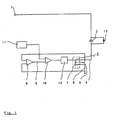
- the electronic contactor control shown in FIG. 1 for controlling a DC contactor is supplied with a supply voltage at the input terminal 1.
- the current through the contactor coil 2 is clocked with the integrated power semiconductor circuit 3 for the purpose of current regulation. So that the contactor does not drop out in the switching-off phases of the clocking, a freewheeling circuit with a diode 13 which is known for the operation of direct current contactors is provided.
- the current control requires a measurement of the current flowing through the contactor coil.
- the measurement output 6 of the integrated power semiconductor circuit 3 is used for this purpose.
- a HEXSense module from International Rectifier is used as circuit 3. Around 1600 MOSFETs are connected in parallel in this module. The stream divides thereby evenly on the individual MOSFETs.
- the source connection of a MOSFET is led to the outside with an extra connection, the measuring output 6. About one thousand six hundredth of the total current is recorded at this connection. The manufacturer specifies the exact ratio of the number of MOSFETs to the measuring MOSFET using a scale factor assigned to the respective module.
- the current of the measuring output 6 is converted with an operational amplifier 8 into a voltage which is applied to the negative input of a comparator 10.
- the output signal of a reference voltage transmitter 11 is connected to the positive input of this comparator 10. If the actual value voltage for the contactor current is greater than the reference voltage, the output of the comparator tilts from a positive voltage value to OV and thus starts the switch-off timer 12, which controls the switch-off phases of the current clocking.
- a contactor control is shown in FIG. 2, with which both the switch-on and the holding current of a contactor are regulated.
- two different reference voltages are provided by a reference voltage generator 14; a higher reference voltage for the short-term inrush current and a lower reference voltage for the holding current of the contactor.
- the switchover of the reference values takes place with an electronic switch 15, which is controlled by an electronic timer 16 and switches the reference voltages to the comparator 10 one after the other.
- the timer 16 starts immediately when the supply voltage is present with the inrush current phase.
- the presence of the supply voltage is checked with an electronic threshold switch 17, which is arranged in the input of the contactor control. If the supply voltage has not exceeded a defined switching threshold, then the start of the timer 16 is prevented.
- the threshold switch 17 also controls the switching off of the contactor control. If the supply voltage drops below a defined switch-off threshold, then there is no reference voltage at the comparator 10 and the semiconductor circuit 3 is blocked. With the threshold switch 17 a defined switching on and off of the contactor is achieved and the fluttering of the contactor is avoided.
Landscapes
- Engineering & Computer Science (AREA)
- Power Engineering (AREA)
- Electronic Switches (AREA)
- Control Of Voltage And Current In General (AREA)
- Relay Circuits (AREA)
- Emergency Protection Circuit Devices (AREA)
- Dc-Dc Converters (AREA)
Applications Claiming Priority (2)
| Application Number | Priority Date | Filing Date | Title |
|---|---|---|---|
| DE3908192A DE3908192A1 (de) | 1989-03-14 | 1989-03-14 | Elektronische schuetzansteuerung |
| DE3908192 | 1989-03-14 |
Publications (3)
| Publication Number | Publication Date |
|---|---|
| EP0387729A2 true EP0387729A2 (fr) | 1990-09-19 |
| EP0387729A3 EP0387729A3 (en) | 1990-11-22 |
| EP0387729B1 EP0387729B1 (fr) | 1995-05-03 |
Family
ID=6376264
Family Applications (1)
| Application Number | Title | Priority Date | Filing Date |
|---|---|---|---|
| EP90104583A Expired - Lifetime EP0387729B1 (fr) | 1989-03-14 | 1990-03-10 | Commande électronique d'un contacteur |
Country Status (6)
| Country | Link |
|---|---|
| US (1) | US5113307A (fr) |
| EP (1) | EP0387729B1 (fr) |
| JP (1) | JP3057571B2 (fr) |
| DE (2) | DE3908192A1 (fr) |
| DK (1) | DK0387729T3 (fr) |
| ES (1) | ES2073467T3 (fr) |
Cited By (3)
| Publication number | Priority date | Publication date | Assignee | Title |
|---|---|---|---|---|
| DE19524003A1 (de) * | 1995-06-30 | 1997-01-09 | Siemens Ag | Elektronische Schaltungsanordnung zur Relaisansteuerung |
| DE102010042050A1 (de) | 2010-10-06 | 2012-04-12 | Robert Bosch Gmbh | Verfahren zum Betreiben einer elektrischen Maschine |
| EP3309811A1 (fr) * | 2016-10-11 | 2018-04-18 | Siemens Aktiengesellschaft | Protection comprenant une commande de bobine électronique |
Families Citing this family (10)
| Publication number | Priority date | Publication date | Assignee | Title |
|---|---|---|---|---|
| DE4026427C1 (fr) * | 1990-08-21 | 1992-02-13 | Siemens Ag, 8000 Muenchen, De | |
| JPH06169269A (ja) * | 1992-11-30 | 1994-06-14 | Fujitsu Ltd | 給電切換リレー回路 |
| DE9406446U1 (de) * | 1993-06-25 | 1994-11-03 | Siemens Ag | Ansteuerbaustein zur Ansteuerung eines Schützes |
| US5914849A (en) * | 1994-04-26 | 1999-06-22 | Kilovac Corporation | DC actuator control circuit with voltage compensation, current control and fast dropout period |
| JP2854538B2 (ja) * | 1995-05-19 | 1999-02-03 | アイシン・エィ・ダブリュ株式会社 | リニアソレノイド弁の制御装置 |
| SE505747C2 (sv) * | 1996-02-07 | 1997-10-06 | Asea Brown Boveri | Kontaktorutrustning |
| EP0793343B1 (fr) * | 1996-02-29 | 2001-07-18 | Co.Ri.M.Me. Consorzio Per La Ricerca Sulla Microelettronica Nel Mezzogiorno | Circuit programmable avec limitation de courant pour les actuateurs de puissance |
| US5784244A (en) * | 1996-09-13 | 1998-07-21 | Cooper Industries, Inc. | Current limiting circuit |
| DE10358858A1 (de) * | 2003-12-16 | 2005-07-14 | Robert Bosch Gmbh | Verfahren und Vorrichtung zum Betreiben einer induktiven Last mit unterschiedlichen elektrischen Spannungen |
| WO2015177919A1 (fr) * | 2014-05-23 | 2015-11-26 | 三菱電機株式会社 | Dispositif de pilotage d'électroaimant |
Family Cites Families (17)
| Publication number | Priority date | Publication date | Assignee | Title |
|---|---|---|---|---|
| US4327394A (en) * | 1978-02-27 | 1982-04-27 | The Bendix Corporation | Inductive load drive circuit utilizing a bi-level output comparator and a flip-flop to set three different levels of load current |
| DE2841781A1 (de) * | 1978-09-26 | 1980-04-10 | Bosch Gmbh Robert | Einrichtung zum betrieb von elektromagnetischen verbrauchern bei brennkraftmaschinen |
| DE3047488A1 (de) * | 1980-12-17 | 1982-07-22 | Brown, Boveri & Cie Ag, 6800 Mannheim | Elektronische schaltungsanordnung fuer ein elektromagnetisches schaltgeraet |
| DE3135805A1 (de) * | 1981-09-10 | 1983-03-24 | Robert Bosch Gmbh, 7000 Stuttgart | Elektrische schaltungsanordnung in verbindung mit einem kfz-steuergeraet |
| US4453652A (en) * | 1981-09-16 | 1984-06-12 | Nordson Corporation | Controlled current solenoid driver circuit |
| DE3204234C2 (de) * | 1981-10-13 | 1985-08-29 | Erwin Sick Gmbh Optik-Elektronik, 7808 Waldkirch | Schaltungsanordnung zur Steuerung eines Relais |
| US4453194A (en) * | 1982-03-01 | 1984-06-05 | International Business Machines Corporation | Integrated power circuit with current sensing means |
| JPS59143231A (ja) * | 1983-02-07 | 1984-08-16 | 三菱電機株式会社 | リレ−駆動装置 |
| DE3333833A1 (de) * | 1983-09-20 | 1985-04-04 | Brown, Boveri & Cie Ag, 6800 Mannheim | Schaltungsanordnung zum gleichstrombetrieb fuer schuetze |
| US4667117A (en) * | 1984-10-31 | 1987-05-19 | International Business Machines Corporation | Self-timing and self-compensating print wire actuator driver |
| JPS61187304A (ja) * | 1985-02-15 | 1986-08-21 | Togami Electric Mfg Co Ltd | 直流電磁石装置 |
| DE3515951A1 (de) * | 1985-05-03 | 1986-11-06 | Siemens AG, 1000 Berlin und 8000 München | Ansteuerschaltung fuer ein monostabiles relais |
| CN1005509B (zh) * | 1985-05-06 | 1989-10-18 | 西门子公司 | 电磁开关的控制装置 |
| US4661766A (en) * | 1985-12-23 | 1987-04-28 | Caterpillar Inc. | Dual current sensing driver circuit |
| DE3701985A1 (de) * | 1987-01-23 | 1988-08-04 | Knorr Bremse Ag | Vorschaltelektronik fuer ein gleichspannungserregbares geraet |
| JPH0666472B2 (ja) * | 1987-06-22 | 1994-08-24 | 日産自動車株式会社 | 過電流保護機能を備えたmosfet |
| FR2617634B1 (fr) * | 1987-07-03 | 1989-12-08 | Petercem Sa | Dispositif de commande et de controle de contacteur, et procede de controle correspondant |
-
1989
- 1989-03-14 DE DE3908192A patent/DE3908192A1/de active Granted
-
1990
- 1990-03-06 US US07/487,897 patent/US5113307A/en not_active Expired - Lifetime
- 1990-03-10 ES ES90104583T patent/ES2073467T3/es not_active Expired - Lifetime
- 1990-03-10 DE DE59008993T patent/DE59008993D1/de not_active Expired - Fee Related
- 1990-03-10 EP EP90104583A patent/EP0387729B1/fr not_active Expired - Lifetime
- 1990-03-10 DK DK90104583.1T patent/DK0387729T3/da active
- 1990-03-13 JP JP2060167A patent/JP3057571B2/ja not_active Expired - Lifetime
Cited By (6)
| Publication number | Priority date | Publication date | Assignee | Title |
|---|---|---|---|---|
| DE19524003A1 (de) * | 1995-06-30 | 1997-01-09 | Siemens Ag | Elektronische Schaltungsanordnung zur Relaisansteuerung |
| DE102010042050A1 (de) | 2010-10-06 | 2012-04-12 | Robert Bosch Gmbh | Verfahren zum Betreiben einer elektrischen Maschine |
| WO2012045506A1 (fr) | 2010-10-06 | 2012-04-12 | Robert Bosch Gmbh | Procédé pour faire fonctionner une machine électrique |
| US9083269B2 (en) | 2010-10-06 | 2015-07-14 | Robert Bosch Gmbh | Method for operating an electric machine |
| EP3309811A1 (fr) * | 2016-10-11 | 2018-04-18 | Siemens Aktiengesellschaft | Protection comprenant une commande de bobine électronique |
| US10692675B2 (en) | 2016-10-11 | 2020-06-23 | Siemens Aktiengesellschaft | Contactor having electronic coil control |
Also Published As
| Publication number | Publication date |
|---|---|
| ES2073467T3 (es) | 1995-08-16 |
| US5113307A (en) | 1992-05-12 |
| DK0387729T3 (da) | 1995-09-18 |
| JPH02281527A (ja) | 1990-11-19 |
| JP3057571B2 (ja) | 2000-06-26 |
| EP0387729B1 (fr) | 1995-05-03 |
| DE59008993D1 (de) | 1995-06-08 |
| DE3908192C2 (fr) | 1991-11-28 |
| DE3908192A1 (de) | 1990-09-20 |
| EP0387729A3 (en) | 1990-11-22 |
Similar Documents
| Publication | Publication Date | Title |
|---|---|---|
| DE3908192C2 (fr) | ||
| DE102006061183A1 (de) | Energieversorgungssteuerung | |
| DE19755669A1 (de) | Antriebssystem für ein Solenoidventil | |
| DE19704089C2 (de) | Verfahren zur Steuerung eines Zerhacker(Chopper)-Treibers und Schaltungsanordnung zur Durchführung des Verfahrens | |
| WO2000062393A1 (fr) | Circuit de protection pour appareil electronique | |
| EP0119452B1 (fr) | Agencement d'un circuit de régulation de la puissance de chauffe à un élément chauffant | |
| DE4403375A1 (de) | Einrichtung und Verfahren zum Steuern eines induktiven Verbrauchers | |
| DE3218583A1 (de) | Schaltervorrichtung zum oeffnen und schliessen eines elektrischen stromkreises | |
| DE19648562C2 (de) | Verfahren und Vorrichtung zur Stromüberwachung für Halbleiterschaltungen | |
| DE2453979A1 (de) | Spannungswandler, insbesondere fuer elektrofahrzeuge | |
| EP0109540A2 (fr) | Agencement de commutation pour l'actionnement d'appareillages de commutation électromagnétiques | |
| DE4123105A1 (de) | Verfahren und vorrichtung zur regelung der ansteuerleistung elektrischer verbraucher | |
| DE2258862A1 (de) | Steuerschaltung zur schnellerregung elektromagnetischer systeme, insbesondere eines schrittmotors | |
| EP0673560B1 (fr) | Convertisseur | |
| DD158156A5 (de) | Vom wechselstromnetz gespeister,in beiden drehrichtungen bremsbarer umkehrantrieb | |
| EP0352593A2 (fr) | Dispositif de surveillance pour un ventilateur | |
| EP0433592A1 (fr) | Minuterie commandée par ordinateur | |
| EP0361212B1 (fr) | Circuit de protection pour un transistor de commutation | |
| DE10159645B4 (de) | Verfahren und Vorrichtung zur Aufrechterhaltung einer Versorgungsspannung einer Stromversorgung einer Elektronik eines Matrixumrichters bei Netzunterbrechung | |
| DE102018122269A1 (de) | Relaismodul | |
| DE3109315A1 (de) | Spannungsquelle mit strombegrenzung fuer die konstantstromansteuerung von schrittmotoren | |
| DE1588405B1 (de) | Stromversorgungseinrichtung zum Aufladen einer Kraftfahrzeugbatterie | |
| DE4006838A1 (de) | Verfahren und anordnung zum schalten eines elektromechanischen relais | |
| DE3504200A1 (de) | Kurzschlussueberwachung fuer schaltregler | |
| DE1588405C (de) | Stromversorgungseinrichtung zum Aufla den einer Krafttahrzeugbattene |
Legal Events
| Date | Code | Title | Description |
|---|---|---|---|
| PUAI | Public reference made under article 153(3) epc to a published international application that has entered the european phase |
Free format text: ORIGINAL CODE: 0009012 |
|
| AK | Designated contracting states |
Kind code of ref document: A2 Designated state(s): AT BE CH DE DK ES FR GB GR IT LI LU NL SE |
|
| PUAL | Search report despatched |
Free format text: ORIGINAL CODE: 0009013 |
|
| AK | Designated contracting states |
Kind code of ref document: A3 Designated state(s): AT BE CH DE DK ES FR GB GR IT LI LU NL SE |
|
| RBV | Designated contracting states (corrected) |
Designated state(s): CH DE DK ES FR GB IT LI SE |
|
| 17P | Request for examination filed |
Effective date: 19910522 |
|
| 17Q | First examination report despatched |
Effective date: 19940117 |
|
| GRAA | (expected) grant |
Free format text: ORIGINAL CODE: 0009210 |
|
| AK | Designated contracting states |
Kind code of ref document: B1 Designated state(s): CH DE DK ES FR GB IT LI SE |
|
| REF | Corresponds to: |
Ref document number: 59008993 Country of ref document: DE Date of ref document: 19950608 |
|
| ITF | It: translation for a ep patent filed | ||
| ET | Fr: translation filed | ||
| REG | Reference to a national code |
Ref country code: ES Ref legal event code: FG2A Ref document number: 2073467 Country of ref document: ES Kind code of ref document: T3 |
|
| GBT | Gb: translation of ep patent filed (gb section 77(6)(a)/1977) |
Effective date: 19950814 |
|
| REG | Reference to a national code |
Ref country code: DK Ref legal event code: T3 |
|
| PLBE | No opposition filed within time limit |
Free format text: ORIGINAL CODE: 0009261 |
|
| STAA | Information on the status of an ep patent application or granted ep patent |
Free format text: STATUS: NO OPPOSITION FILED WITHIN TIME LIMIT |
|
| 26N | No opposition filed | ||
| REG | Reference to a national code |
Ref country code: CH Ref legal event code: PUE Owner name: LICENTIA PATENT- VERWALTUNGS-GMBH TRANSFER- AEG NI |
|
| REG | Reference to a national code |
Ref country code: GB Ref legal event code: 732E |
|
| REG | Reference to a national code |
Ref country code: FR Ref legal event code: TP |
|
| REG | Reference to a national code |
Ref country code: ES Ref legal event code: PC2A |
|
| REG | Reference to a national code |
Ref country code: GB Ref legal event code: IF02 |
|
| PGFP | Annual fee paid to national office [announced via postgrant information from national office to epo] |
Ref country code: DE Payment date: 20050428 Year of fee payment: 16 |
|
| PG25 | Lapsed in a contracting state [announced via postgrant information from national office to epo] |
Ref country code: DE Free format text: LAPSE BECAUSE OF NON-PAYMENT OF DUE FEES Effective date: 20061003 |
|
| PGFP | Annual fee paid to national office [announced via postgrant information from national office to epo] |
Ref country code: ES Payment date: 20090326 Year of fee payment: 20 Ref country code: DK Payment date: 20090325 Year of fee payment: 20 |
|
| PGFP | Annual fee paid to national office [announced via postgrant information from national office to epo] |
Ref country code: CH Payment date: 20090325 Year of fee payment: 20 |
|
| PGFP | Annual fee paid to national office [announced via postgrant information from national office to epo] |
Ref country code: SE Payment date: 20090327 Year of fee payment: 20 Ref country code: IT Payment date: 20090331 Year of fee payment: 20 |
|
| PGFP | Annual fee paid to national office [announced via postgrant information from national office to epo] |
Ref country code: FR Payment date: 20090317 Year of fee payment: 20 |
|
| PGFP | Annual fee paid to national office [announced via postgrant information from national office to epo] |
Ref country code: GB Payment date: 20090403 Year of fee payment: 20 |
|
| REG | Reference to a national code |
Ref country code: CH Ref legal event code: PL |
|
| REG | Reference to a national code |
Ref country code: DK Ref legal event code: EUP |
|
| REG | Reference to a national code |
Ref country code: GB Ref legal event code: PE20 Expiry date: 20100309 |
|
| EUG | Se: european patent has lapsed | ||
| REG | Reference to a national code |
Ref country code: ES Ref legal event code: FD2A Effective date: 20100311 |
|
| PG25 | Lapsed in a contracting state [announced via postgrant information from national office to epo] |
Ref country code: GB Free format text: LAPSE BECAUSE OF EXPIRATION OF PROTECTION Effective date: 20100309 |
|
| PG25 | Lapsed in a contracting state [announced via postgrant information from national office to epo] |
Ref country code: ES Free format text: LAPSE BECAUSE OF EXPIRATION OF PROTECTION Effective date: 20100311 |