EP0387761B1 - Interrupteur automatique, en particulier disjonctueur de protection de ligne - Google Patents
Interrupteur automatique, en particulier disjonctueur de protection de ligne Download PDFInfo
- Publication number
- EP0387761B1 EP0387761B1 EP90104653A EP90104653A EP0387761B1 EP 0387761 B1 EP0387761 B1 EP 0387761B1 EP 90104653 A EP90104653 A EP 90104653A EP 90104653 A EP90104653 A EP 90104653A EP 0387761 B1 EP0387761 B1 EP 0387761B1
- Authority
- EP
- European Patent Office
- Prior art keywords
- arc
- pillars
- webs
- switch according
- contact
- Prior art date
- Legal status (The legal status is an assumption and is not a legal conclusion. Google has not performed a legal analysis and makes no representation as to the accuracy of the status listed.)
- Expired - Lifetime
Links
- 239000011810 insulating material Substances 0.000 claims abstract description 10
- 238000010791 quenching Methods 0.000 claims description 29
- 230000000171 quenching effect Effects 0.000 claims description 28
- 238000007789 sealing Methods 0.000 claims description 8
- 230000000694 effects Effects 0.000 claims description 5
- 238000004519 manufacturing process Methods 0.000 claims description 4
- 230000014759 maintenance of location Effects 0.000 claims 1
- 230000000630 rising effect Effects 0.000 abstract 1
- 239000007789 gas Substances 0.000 description 11
- 239000000919 ceramic Substances 0.000 description 2
- 230000001419 dependent effect Effects 0.000 description 2
- 238000011161 development Methods 0.000 description 2
- 230000018109 developmental process Effects 0.000 description 2
- 239000000463 material Substances 0.000 description 2
- 229920001187 thermosetting polymer Polymers 0.000 description 2
- 230000001133 acceleration Effects 0.000 description 1
- 239000011324 bead Substances 0.000 description 1
- 150000001875 compounds Chemical class 0.000 description 1
- 238000010276 construction Methods 0.000 description 1
- 238000001816 cooling Methods 0.000 description 1
- 238000002242 deionisation method Methods 0.000 description 1
- 230000005520 electrodynamics Effects 0.000 description 1
- 238000005516 engineering process Methods 0.000 description 1
- 230000005294 ferromagnetic effect Effects 0.000 description 1
- 239000003302 ferromagnetic material Substances 0.000 description 1
- 239000012634 fragment Substances 0.000 description 1
- 238000009413 insulation Methods 0.000 description 1
- 230000005291 magnetic effect Effects 0.000 description 1
- 230000007257 malfunction Effects 0.000 description 1
- 238000000465 moulding Methods 0.000 description 1
- 239000004033 plastic Substances 0.000 description 1
- 229920001169 thermoplastic Polymers 0.000 description 1
- 238000009757 thermoplastic moulding Methods 0.000 description 1
- 239000004416 thermosoftening plastic Substances 0.000 description 1
Images
Classifications
-
- H—ELECTRICITY
- H01—ELECTRIC ELEMENTS
- H01H—ELECTRIC SWITCHES; RELAYS; SELECTORS; EMERGENCY PROTECTIVE DEVICES
- H01H9/00—Details of switching devices, not covered by groups H01H1/00 - H01H7/00
- H01H9/30—Means for extinguishing or preventing arc between current-carrying parts
- H01H9/34—Stationary parts for restricting or subdividing the arc, e.g. barrier plate
- H01H9/346—Details concerning the arc formation chamber
-
- H—ELECTRICITY
- H01—ELECTRIC ELEMENTS
- H01H—ELECTRIC SWITCHES; RELAYS; SELECTORS; EMERGENCY PROTECTIVE DEVICES
- H01H9/00—Details of switching devices, not covered by groups H01H1/00 - H01H7/00
- H01H9/30—Means for extinguishing or preventing arc between current-carrying parts
- H01H9/34—Stationary parts for restricting or subdividing the arc, e.g. barrier plate
- H01H9/342—Venting arrangements for arc chutes
Definitions
- the invention relates to a circuit breaker according to the preamble of claim 1, in particular a miniature circuit breaker in a narrow construction cf. e.g. FR 25 75 861 B1.
- switches with specially designed quenching chambers are known in a variety of designs.
- the previously known switches contain an arc chamber with extinguishing plates assigned to the contact point within their insulating material housing in order to effectively extinguish the switching arc which arises in the event of a short-circuit shutdown.
- a circuit breaker with integrated arcing means in the prechamber area consist of oppositely formed rows of ribs on the housing inner walls of the arc chamber.
- a central channel remains between the rows of ribs, which have a tree-like structure or can also be formed as individual straight walls.
- they are surrounded by grooves or notches, which in turn contain a deionized cold gas reserve and are intended to ensure gas recirculation in the direction of the contact zone when switched off.
- the rib rows which are located freestanding in the middle of the prechamber area, only widen the creepage distance between the contacts, without the arc and the arc gases being guided in a targeted manner.
- the shape and position of the grooves are essentially matched to the fact that a uniform thickness of the ribs is maintained in order to exclude cavities and unevenness in the housing parts. Design and press engineering measures are therefore in the foreground when designing the rib rows of this switch. Optimized gas recirculation and a rapid discharge of the switching arc from the contact point into the quenching plates, however, are not guaranteed with such a quenching chamber.
- the invention has for its object to simplify the quenching chamber within its prechamber area in a self-switch of the aforementioned type, and to provide improved arc guidance and to bring about a particularly low flow resistance in the prechamber space, so that a quick and safe flow of the switching arc from the contact point into the Extinguishing sheet stack is ensured.
- the design of the quenching chamber according to the invention is advantageous in that the switching arc, driven by the magnetic field of the arc guiding rails, is narrowly delimited between the protruding upper sides of webs which are closely adjacent there and from the end faces of a plurality of columns or pegs arranged in a distributed manner in the prechamber space and runs in a narrow gap.
- this results in high arc acceleration with low gas pressure.
- the drive effect of the gas-emitting material of the webs and columns is used in a targeted manner in order to exert an additional drive on the arc. With closed side panels, however, this effect is usually too strong.
- the gas pressure arising in front of the migrating arc can relax in the spaces between the columns, so that the switching arc finds only a slight flow resistance in the direction of the quenching plates and can therefore run quickly and safely from the contact point.
- any backward pressure difference in front of and behind the arc is effectively compensated for by backflow of the gases between the columns.
- This pressure equalization also ensures good deionization of the area at risk of ignition at the contact point behind the arc.
- the web-like sealing walls enlarge the creepage distances at the contact point. Since the web edges are only slightly loaded by the arc, there is a high insulation resistance even when the contacts are open.
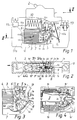
- the narrow circuit breaker has a housing (1) composed of two housing shells (1a, 1b), which accommodates a switching and release mechanism (2), which is only indicated, in the upper part.
- the housing (1) made of thermosetting or thermoplastic molding compound is predominantly designed as an extinguishing chamber (3), which is largely filled with an extinguishing sheet stack (4) arranged parallel to the bottom surface (1c) of the switch.
- the depth of the Extinguishing chamber between their at the inner side surfaces (3a, 3b) is predetermined, based on the standardized switch width, by the outer walls of the housing (1a ', 1b') in the wall thickness that is customary in terms of production technology.
- arc guiding rails (6) and (7) which in turn are in the area a contact arrangement (5) located in the prechamber space (3c) of the arcing chamber.
- the contact point with a single break in the funnel-shaped prechamber space (3c) on the right upper edge of the quenching chamber consists of a fixed contact piece (5a) which is connected to an output terminal (11) via current-carrying parts (10a) and a trigger coil (10), and one by one Fixed axis swiveling contact lever (5b). This is connected to an input terminal (13) via movable lines (12a, 12b) with the inclusion of a thermal release (12) and pivots counterclockwise when it is switched off.
- Fixed contact piece (5a) and contact lever (5b) form an approximately U-shaped current loop at the actual contact point of contact together with their current leads. which is oriented perpendicular to the direction of the extinguishing plates (4a).
- the individual quenching plates have an approximately V-shaped incision (4b) on their front side facing the pre-chamber space (3c) and improve the arc run-in and cover the entire open cross-section of the pre-chamber space, which is mainly enclosed by wall parts (1e), with the front contour formed in this way from. Only a recess required for the pivoting movement of the contact lever (5b) is recessed in the wall parts (1e), so that the prechamber space (3c) in connection with the arc guide rails (6, 7) is designed to be almost pressure-tight to the switching and triggering mechanism.
- the upper web (3d) is tight on the fixed contact piece (5a) and follows its contact horn (5a ') on the side facing the prechamber space up to the quenching chamber wall in the area of the upper arc runner (6). Together they include Crosspieces (3d) of both housing shells the fixed contact piece on the contact side and on both narrow sides such that in the middle between the crosspieces (3d) practically only a gap corresponding to the width of the contact lever (5b) remains free along the arcing horn (5a ').
- Another main feature of the invention is a plurality of columns or pins (3f) arranged in the prechamber space (3c) - still referred to only as columns - which are arranged approximately evenly distributed in the free cross section between the webs (3d, 3e).
- the columns (3f) which are round or square in cross-section, have an approximately equal distance from the webs (3d, 3e) and from one another and each extend from the side surfaces (3a, 3b) to almost the pivoting plane of the contact lever (5b), see above that only a narrow gap between their end faces (3f ') continuously remains free.
- the columns (3f) are preferably arranged in a slight zigzag offset to a middle ideal line between the two webs (3d, 3e) from the contact area in the direction of the fire-extinguishing sheet end faces, but can also be arranged directly in a row on this ideal line. Ideally, only two columns are arranged in the funnel-shaped area directly in front of the quenching plates (4a) (FIG. 1, FIG. 3). According to the exemplary embodiment, seven columns (3f) are formed on each housing half-shell (1a, 1b) directly during the manufacture of the housing parts, the columns preferably being slightly frustoconical in shape with an average diameter of approximately 2 mm and a height of approximately 6 mm.
- the arrangement of the columns (3f) is of the named ones Criteria with dependent.
- the number of pillars on each housing part will essentially depend on the size of the prechamber space, while their position should be distributed as evenly as possible between the contact point area and the quenching plate end faces.
- the column groups are in the two housing shells arranged offset to a gap, as indicated in particular in FIG. 2.
- the existing expansion space and the flow channels around the columns also ensure a lower gas pressure, which in turn reduces the ion concentration and reduces the risk of reignitions behind the arc.
- the space behind the fixed contact piece (5a) can serve as a kind of buffer and as a cooling air mass reserve, if the web (3d) that surrounds the contact horn up to the upper arc runner (6) ends approximately with the top of the contact point - this leaves between the end of the contact point Web (3d) and the wall part (1e) a cross-flow channel (8 '), which enables pressure equalization above the contact point to the actual antechamber (3c).
Landscapes
- Arc-Extinguishing Devices That Are Switches (AREA)
- Circuit Breakers (AREA)
- Breakers (AREA)
- Shearing Machines (AREA)
- Crushing And Pulverization Processes (AREA)
- Keying Circuit Devices (AREA)
- Driving Mechanisms And Operating Circuits Of Arc-Extinguishing High-Tension Switches (AREA)
Claims (15)
- Interrupteur automatique comportant un boîtier (1) fabriqué en matériau isolant et recevant le mécanisme de commutation (2), et comportant une chambre d'extinction (3) entourée par le boîtier, laquelle présente une antichambre (3e) flanquant le dispositif de contact (5) avec des moyens de guidage (3f) de l'arc électrique qui font saillie hors du boîtier et sont intégrés à celui-ci, pour introduire l'arc de coupure (9, 9′, 9") depuis le point de contact dans une région d'extinction de l'arc, en particulier un empilement de tôles d'extinction (4) qui, de son côté, ferme sur le côté opposé au point de contact l'antichambre (3c) s'élargissant en forme d'entonnoir, depuis le dispositif de contact (5) jusqu'aux tôles d'extinction (4), et pourvue de rails de guidage de l'arc (5a′, 6, 7), caractérisé en ce que des entretoises (3d, 3e) accolées en matériau isolant sont agencées dans l'antichambre (3c) sur au moins une face latérale des faces latérales (3a, 3b) intérieures du boîtier (1), se trouvant approximativement parallèles au plan du mouvement d'ouverture du contact du levier de contact (5b), en partant approximativement du dispositif de contact (5) et à partir de là le long des rails de guidage (5a′, 6, 7) de l'arc, lesdites entretoises entourant les rails de guidage (5a′, 6, 7) de l'arc jusqu'à l'antichambre (3c), hormis une fente dans le plan d'ouverture du contact et formant en même temps des parois d'étanchéité par rapport au mécanisme de commutation (2), et en ce que dans le canal d'écoulement (8) subsistant de l'antichambre (3c), plusieurs colonnes ou tenons (3f), faisant saillie depuis le fond des faces latérales (3a, 3b) en direction du plan d'ouverture de contact, sont agencées entre les parois d'étanchéité (3d, 3e; 1e), selon une répartition approximativement régulière, de telle sorte qu'avec leurs faces frontales (3f′) et en coopération avec les entretoises (3d, 3e), elles forment un guidage latéral étroit de l'arc de coupure (9) pour une faible surface de contact et en ce qu'il reste entre les colonnes ou tenons (3f) une chambre d'expansion de gaz de grande taille, malgré le guidage étroit.
- Interrupteur selon la revendication 1, caractérisé en ce que les colonnes (3f) sont réparties à l'intérieur du canal d'écoulement (8) entre les parois d'étanchéité (3d, 3e) ainsi que les unes par rapport aux autres, de telle sorte que des cercles imaginaires autour de leurs racines, de diamètres approximativement égaux, sont respectivement tangents non seulement à ceux qui leur sont voisins, mais aussi aux parois d'étanchéité sur la périphérie.
- Interrupteur selon l'une ou l'autre des revendications 1 à 2, caractérisé en ce que les colonnes (3f) sont agencées à peu près à même distance dans une rangée, ponctuellement les unes derrière les autres.
- Interrupteur selon l'une quelconque des revendications 1 à 3, caractérisé en ce que les colonnes (3f) avec leurs racines sont agencées sur une ligne d'arc idéale à proximité au milieu entre les entretoises (3d, 3e) recourbées.
- Interrupteur selon l'une quelconque des revendications 1 à 3, caractérisé en ce que les colonnes (3f) avec leurs racines sont agencées à la façon d'une ligne en zigzag sur les faces latérales (3a, 3b), réparties presque régulièrement entre les entretoises (3d, 3e) dans le canal d'écoulement (8).
- Interrupteur selon l'une quelconque des revendications 1 à 5, caractérisé en ce que les colonnes (3f) d'une face latérale (3a) sont agencées à décalage dans les intervalles respectifs, par rapport à celles de l'autre face latérale (3b) du boîtier (1).
- Interrupteur selon l'une quelconque des revendications 1 à 6, caractérisé en ce que les colonnes (3f) d'une face latérale (3a ou 3b, respectivement) sont réalisées de la même hauteur que les entretoises (3d, 3e) correspondantes et présentent des faces frontales (3f′) se trouvant dans un plan.
- Interrupteur selon l'une quelconque des revendications 1 à 7, caractérisé en ce que les entretoises (3d, 3e) et aussi les colonnes (3f) sont directement formées lors de la fabrication des parties (1a, 1b) du boîtier.
- Interrupteur selon l'une quelconque des revendications 1 à 8, caractérisé en ce que de préférence entre cinq et neuf colonnes (3f) sont agencées sur chaque face latérale (3a, 3b) à l'intérieur de l'antichambre (3c).
- Interrupteur selon l'une quelconque des revendications 1 à 9, caractérisé en ce qu'environ 5 à 15% de la surface totale du canal d'écoulement (8) entre les parois d'étanchéité (entretoises 3d, 3e, partie de paroi 1e), sont couverts par la surface de base des colonnes (3f).
- Interrupteur selon l'une quelconque des revendications 1 à 10, caractérisé en ce que les colonnes (3f) sont réalisées de forme ronde ou polygonale et présentent un diamètre ou une longueur latérale d'environ 2 mm.
- Interrupteur selon l'une quelconque des revendications 1 à 11, caractérisé en ce que les colonnes (3f) présentent des deux côtés du plan d'ouverture de contact respectivement une hauteur d'environ 6 mm.
- Interrupteur selon l'une quelconque des revendications 1 à 12, caractérisé en ce que les colonnes (3f) sont réalisées en se rétrécissant avec une conicité d'environ 10° en direction du plan d'ouverture de contact.
- Interrupteur selon l'une quelconque des revendications 1 à 13, caractérisé en ce que la fente entre les faces frontales (3f′) des colonnes (3f) et les faces supérieures des entretoises (3d, 3e) des deux demi-coquilles (1a, 1b) du boîtier (1) présente une largeur d'environ 3 mm.
- Interrupteur selon l'une quelconque des revendications 1 à 14, caractérisé en ce que les entretoises (3d, 3e) sont réalisées pour positionner et maintenir d'une part le plot de contact fixe (5a) avec la corne de contact (5a′) et d'autre part le rail de guidage intérieur (7) de l'arc.
Applications Claiming Priority (4)
| Application Number | Priority Date | Filing Date | Title |
|---|---|---|---|
| DE3908102 | 1989-03-13 | ||
| DE19893908102 DE3908102A1 (de) | 1989-03-13 | 1989-03-13 | Selbstschalter, insbesondere leitungsschutzschalter |
| DE4007606A DE4007606A1 (de) | 1990-03-09 | 1990-03-09 | Selbstschalter, insbesondere leitungsschutzschalter |
| DE4007606 | 1990-03-09 |
Publications (3)
| Publication Number | Publication Date |
|---|---|
| EP0387761A2 EP0387761A2 (fr) | 1990-09-19 |
| EP0387761A3 EP0387761A3 (fr) | 1992-01-29 |
| EP0387761B1 true EP0387761B1 (fr) | 1994-12-14 |
Family
ID=25878766
Family Applications (1)
| Application Number | Title | Priority Date | Filing Date |
|---|---|---|---|
| EP90104653A Expired - Lifetime EP0387761B1 (fr) | 1989-03-13 | 1990-03-12 | Interrupteur automatique, en particulier disjonctueur de protection de ligne |
Country Status (5)
| Country | Link |
|---|---|
| EP (1) | EP0387761B1 (fr) |
| AT (1) | ATE115767T1 (fr) |
| DE (1) | DE59007970D1 (fr) |
| ES (1) | ES2065420T3 (fr) |
| HK (1) | HK64895A (fr) |
Cited By (1)
| Publication number | Priority date | Publication date | Assignee | Title |
|---|---|---|---|---|
| DE19860427A1 (de) * | 1998-12-28 | 2000-06-29 | Abb Patent Gmbh | Elektrisches Schaltgerät, insbesondere Leitungsschutzschalter |
Families Citing this family (4)
| Publication number | Priority date | Publication date | Assignee | Title |
|---|---|---|---|---|
| CN103441049B (zh) * | 2013-09-06 | 2015-07-22 | 浙江大华电气有限公司 | 一种加强自励磁场强度的引弧结构 |
| WO2015151393A1 (fr) * | 2014-03-31 | 2015-10-08 | パナソニックIpマネジメント株式会社 | Disjoncteur |
| CN105185671B (zh) * | 2015-10-30 | 2019-06-25 | 上海电科电器科技有限公司 | 断路器及其挡板 |
| CN108281334B (zh) * | 2016-11-30 | 2018-12-28 | 杭州曼京科技有限公司 | 一种电力断路器机械挤压灭弧机构 |
Family Cites Families (4)
| Publication number | Priority date | Publication date | Assignee | Title |
|---|---|---|---|---|
| DE3413555A1 (de) * | 1984-04-11 | 1985-10-24 | Brown, Boveri & Cie Ag, 6800 Mannheim | Loescheinrichtung fuer elektrische schalter |
| FR2575861B1 (fr) * | 1985-01-07 | 1987-01-16 | Merlin Gerin | Disjoncteur electrique miniature a chambre de formation d'arc |
| DE3619241C2 (de) * | 1986-06-07 | 1994-07-21 | Kloeckner Moeller Gmbh | Löscheinrichtung für einen Leitungsschutzschalter |
| DE3621690A1 (de) * | 1986-06-27 | 1988-01-14 | Bbc Brown Boveri & Cie | Loescheinrichtung fuer elektrische schalter |
-
1990
- 1990-03-12 EP EP90104653A patent/EP0387761B1/fr not_active Expired - Lifetime
- 1990-03-12 AT AT90104653T patent/ATE115767T1/de not_active IP Right Cessation
- 1990-03-12 ES ES90104653T patent/ES2065420T3/es not_active Expired - Lifetime
- 1990-03-12 DE DE59007970T patent/DE59007970D1/de not_active Expired - Fee Related
-
1995
- 1995-04-27 HK HK64895A patent/HK64895A/xx not_active IP Right Cessation
Cited By (2)
| Publication number | Priority date | Publication date | Assignee | Title |
|---|---|---|---|---|
| DE19860427A1 (de) * | 1998-12-28 | 2000-06-29 | Abb Patent Gmbh | Elektrisches Schaltgerät, insbesondere Leitungsschutzschalter |
| DE19860427B4 (de) * | 1998-12-28 | 2006-08-03 | Abb Patent Gmbh | Elektrisches Schaltgerät, insbesondere Leitungsschutzschalter |
Also Published As
| Publication number | Publication date |
|---|---|
| EP0387761A2 (fr) | 1990-09-19 |
| DE59007970D1 (de) | 1995-01-26 |
| ATE115767T1 (de) | 1994-12-15 |
| HK64895A (en) | 1995-05-05 |
| ES2065420T3 (es) | 1995-02-16 |
| EP0387761A3 (fr) | 1992-01-29 |
Similar Documents
| Publication | Publication Date | Title |
|---|---|---|
| DE919722C (de) | Elektrischer Stromunterbrecher | |
| DE728612C (de) | Schalter mit Lichtbogenkammer | |
| EP0752153B2 (fr) | Chambre d'extinction d'arc a trois barrieres de passage des gaz de l'arc | |
| DE3619241C2 (de) | Löscheinrichtung für einen Leitungsschutzschalter | |
| EP0387761B1 (fr) | Interrupteur automatique, en particulier disjonctueur de protection de ligne | |
| DE3908102A1 (de) | Selbstschalter, insbesondere leitungsschutzschalter | |
| DE4007606A1 (de) | Selbstschalter, insbesondere leitungsschutzschalter | |
| DE1063246B (de) | Lichtbogenloeschkammer fuer Schalter grosser Abschaltleistung | |
| DE969297C (de) | Elektrischer Trennschalter | |
| DE19860427B4 (de) | Elektrisches Schaltgerät, insbesondere Leitungsschutzschalter | |
| DE1005153B (de) | Lichtbogenloeschvorrichtung fuer elektrische Schalter | |
| DE3337562A1 (de) | Loescheinrichtung fuer einen leitungsschutzschalter | |
| EP0183145B1 (fr) | Appareil de commutation électrique, notamment disjoncteur de puissance et de protection | |
| EP0051756B1 (fr) | Dispositif d'extinction d'arc éléctrique, notamment pour disjoncteur de protection | |
| DE2916368C2 (de) | Kathode für eine Gasentladungsanzeigevorrichtung | |
| DE102007001802B4 (de) | Elektrisches Schaltgerät | |
| DE2816352C2 (de) | Niederspannungs-Leistungsschalter mit Lichtbogenraum und Schaltmechanismus | |
| DE1790089C3 (fr) | ||
| DE2741868C2 (de) | Lichtbogenkammer mit Lichtbogenlaufschienen und perforierten Keramikplatten | |
| DE2949012A1 (de) | Lichtbogenkammer eines leitungsschutzschalters | |
| DE1027280B (de) | Stromunterbrecher mit einem Schacht zum Aufnehmen und Loeschen des Schaltlichtbogens | |
| EP0231733A2 (fr) | Chambre d'extinction d'arc | |
| DE19643643B4 (de) | Leitungsschutzschalter mit Lichtbogenlöschkammer und Entionisierungseinrichtung | |
| DE3307062C2 (de) | Lichtbogenlöschkammer | |
| AT404770B (de) | Lichtbogenlöschkammer für schalter |
Legal Events
| Date | Code | Title | Description |
|---|---|---|---|
| PUAI | Public reference made under article 153(3) epc to a published international application that has entered the european phase |
Free format text: ORIGINAL CODE: 0009012 |
|
| AK | Designated contracting states |
Kind code of ref document: A2 Designated state(s): AT BE CH DE ES FR GB GR IT LI NL |
|
| PUAL | Search report despatched |
Free format text: ORIGINAL CODE: 0009013 |
|
| AK | Designated contracting states |
Kind code of ref document: A3 Designated state(s): AT BE CH DE ES FR GB GR IT LI NL |
|
| 17P | Request for examination filed |
Effective date: 19920129 |
|
| 17Q | First examination report despatched |
Effective date: 19940322 |
|
| GRAA | (expected) grant |
Free format text: ORIGINAL CODE: 0009210 |
|
| AK | Designated contracting states |
Kind code of ref document: B1 Designated state(s): AT BE CH DE ES FR GB GR IT LI NL |
|
| REF | Corresponds to: |
Ref document number: 115767 Country of ref document: AT Date of ref document: 19941215 Kind code of ref document: T |
|
| REF | Corresponds to: |
Ref document number: 59007970 Country of ref document: DE Date of ref document: 19950126 |
|
| GBT | Gb: translation of ep patent filed (gb section 77(6)(a)/1977) |
Effective date: 19950110 |
|
| REG | Reference to a national code |
Ref country code: ES Ref legal event code: FG2A Ref document number: 2065420 Country of ref document: ES Kind code of ref document: T3 |
|
| ET | Fr: translation filed | ||
| ITF | It: translation for a ep patent filed | ||
| REG | Reference to a national code |
Ref country code: GR Ref legal event code: FG4A Free format text: 3014652 |
|
| PLBE | No opposition filed within time limit |
Free format text: ORIGINAL CODE: 0009261 |
|
| STAA | Information on the status of an ep patent application or granted ep patent |
Free format text: STATUS: NO OPPOSITION FILED WITHIN TIME LIMIT |
|
| 26N | No opposition filed | ||
| REG | Reference to a national code |
Ref country code: CH Ref legal event code: PUE Owner name: LICENTIA PATENT- VERWALTUNGS-GMBH TRANSFER- AEG NI |
|
| REG | Reference to a national code |
Ref country code: GB Ref legal event code: 732E |
|
| NLS | Nl: assignments of ep-patents |
Owner name: AEG NIEDERSPANNUNGSTECHNIK GMBH & CO. KG |
|
| REG | Reference to a national code |
Ref country code: FR Ref legal event code: TP |
|
| REG | Reference to a national code |
Ref country code: ES Ref legal event code: PC2A |
|
| REG | Reference to a national code |
Ref country code: GB Ref legal event code: IF02 |
|
| PGFP | Annual fee paid to national office [announced via postgrant information from national office to epo] |
Ref country code: GR Payment date: 20060227 Year of fee payment: 17 |
|
| PGFP | Annual fee paid to national office [announced via postgrant information from national office to epo] |
Ref country code: NL Payment date: 20060321 Year of fee payment: 17 Ref country code: AT Payment date: 20060321 Year of fee payment: 17 |
|
| PGFP | Annual fee paid to national office [announced via postgrant information from national office to epo] |
Ref country code: GB Payment date: 20060322 Year of fee payment: 17 |
|
| PGFP | Annual fee paid to national office [announced via postgrant information from national office to epo] |
Ref country code: CH Payment date: 20060406 Year of fee payment: 17 |
|
| PGFP | Annual fee paid to national office [announced via postgrant information from national office to epo] |
Ref country code: DE Payment date: 20060929 Year of fee payment: 17 |
|
| REG | Reference to a national code |
Ref country code: CH Ref legal event code: PL |
|
| PG25 | Lapsed in a contracting state [announced via postgrant information from national office to epo] |
Ref country code: AT Free format text: LAPSE BECAUSE OF NON-PAYMENT OF DUE FEES Effective date: 20070312 |
|
| GBPC | Gb: european patent ceased through non-payment of renewal fee |
Effective date: 20070312 |
|
| NLV4 | Nl: lapsed or anulled due to non-payment of the annual fee |
Effective date: 20071001 |
|
| PG25 | Lapsed in a contracting state [announced via postgrant information from national office to epo] |
Ref country code: DE Free format text: LAPSE BECAUSE OF NON-PAYMENT OF DUE FEES Effective date: 20071002 Ref country code: NL Free format text: LAPSE BECAUSE OF NON-PAYMENT OF DUE FEES Effective date: 20071001 |
|
| PG25 | Lapsed in a contracting state [announced via postgrant information from national office to epo] |
Ref country code: LI Free format text: LAPSE BECAUSE OF NON-PAYMENT OF DUE FEES Effective date: 20070331 Ref country code: CH Free format text: LAPSE BECAUSE OF NON-PAYMENT OF DUE FEES Effective date: 20070331 |
|
| PG25 | Lapsed in a contracting state [announced via postgrant information from national office to epo] |
Ref country code: GB Free format text: LAPSE BECAUSE OF NON-PAYMENT OF DUE FEES Effective date: 20070312 |
|
| PG25 | Lapsed in a contracting state [announced via postgrant information from national office to epo] |
Ref country code: GR Free format text: LAPSE BECAUSE OF NON-PAYMENT OF DUE FEES Effective date: 20071003 |
|
| PGFP | Annual fee paid to national office [announced via postgrant information from national office to epo] |
Ref country code: ES Payment date: 20090326 Year of fee payment: 20 |
|
| PGFP | Annual fee paid to national office [announced via postgrant information from national office to epo] |
Ref country code: IT Payment date: 20090331 Year of fee payment: 20 |
|
| PGFP | Annual fee paid to national office [announced via postgrant information from national office to epo] |
Ref country code: BE Payment date: 20090430 Year of fee payment: 20 |
|
| PGFP | Annual fee paid to national office [announced via postgrant information from national office to epo] |
Ref country code: FR Payment date: 20090317 Year of fee payment: 20 |
|
| BE20 | Be: patent expired |
Owner name: *AEG NIEDERSPANNUNGSTECHNIK G.M.B.H. & CO. K.G. Effective date: 20100312 |
|
| REG | Reference to a national code |
Ref country code: ES Ref legal event code: FD2A Effective date: 20100313 |
|
| PG25 | Lapsed in a contracting state [announced via postgrant information from national office to epo] |
Ref country code: ES Free format text: LAPSE BECAUSE OF EXPIRATION OF PROTECTION Effective date: 20100313 |