EP0387891A2 - Réacteur à neutrons rapides et procédé pour le ravitaillement de combustible - Google Patents
Réacteur à neutrons rapides et procédé pour le ravitaillement de combustible Download PDFInfo
- Publication number
- EP0387891A2 EP0387891A2 EP90104983A EP90104983A EP0387891A2 EP 0387891 A2 EP0387891 A2 EP 0387891A2 EP 90104983 A EP90104983 A EP 90104983A EP 90104983 A EP90104983 A EP 90104983A EP 0387891 A2 EP0387891 A2 EP 0387891A2
- Authority
- EP
- European Patent Office
- Prior art keywords
- core
- fuel
- fuel assemblies
- multiplication factor
- fast neutron
- Prior art date
- Legal status (The legal status is an assumption and is not a legal conclusion. Google has not performed a legal analysis and makes no representation as to the accuracy of the status listed.)
- Withdrawn
Links
Images










Classifications
-
- G—PHYSICS
- G21—NUCLEAR PHYSICS; NUCLEAR ENGINEERING
- G21C—NUCLEAR REACTORS
- G21C1/00—Reactor types
- G21C1/02—Fast fission reactors, i.e. reactors not using a moderator ; Metal cooled reactors; Fast breeders
- G21C1/022—Fast fission reactors, i.e. reactors not using a moderator ; Metal cooled reactors; Fast breeders characterised by the design or properties of the core
-
- Y—GENERAL TAGGING OF NEW TECHNOLOGICAL DEVELOPMENTS; GENERAL TAGGING OF CROSS-SECTIONAL TECHNOLOGIES SPANNING OVER SEVERAL SECTIONS OF THE IPC; TECHNICAL SUBJECTS COVERED BY FORMER USPC CROSS-REFERENCE ART COLLECTIONS [XRACs] AND DIGESTS
- Y02—TECHNOLOGIES OR APPLICATIONS FOR MITIGATION OR ADAPTATION AGAINST CLIMATE CHANGE
- Y02E—REDUCTION OF GREENHOUSE GAS [GHG] EMISSIONS, RELATED TO ENERGY GENERATION, TRANSMISSION OR DISTRIBUTION
- Y02E30/00—Energy generation of nuclear origin
- Y02E30/30—Nuclear fission reactors
Definitions
- the present invention relates to a core of a fast neutron reactor and, more particularly, to a method of refueling in a fast breeder core suitable for realizing a transition to a core state which exhibits superior performance.
- Fast neutron reactor features an economical use of fuel due to phenomenon known as "breeding" in which neutrons generated by, for example, by fission in the core are absorbed by a fertile material so as to generate fissile material.
- the core of such a fast neutron reactor has a plurality of fuel assemblies bundled in a cylindrical or columnar form, each fuel assembly including a plurality of stainless steel cladding tubes each being charged with fuel pellets, the cladding tubes being covered with hexagonal wrapper tube made of a stainless steel.
- the reactor core is surrounded by axial and radial blankets made of fertile materials so as to improve breeding characteristic.
- the reactor core is charged with a fissile material as a fuel, e.g., plutonium-enriched uranium, while uranium oxide, for example, is used as the fertile material of blankets. Neutrons leaked from the reactor core is trapped by the fertile material of the blankets so that effective fissile material are produced.
- a fissile material e.g., plutonium-enriched uranium
- uranium oxide for example
- the power generated in the core is small because the diluted assemblies exhibit small reactivity. Therefore, a part of the initial fuel is replaced with a fuel assembly for equilibrium core in a transition core, the reactivity in the core is increased and, in addition, the new assembly exhibits a greater level of power than surrounding assemblies. This causes an increase in the maximum linear power density and, hence, a reduction in the thermal margin of the fuel.
- a fast neutron reactor core exhibits a greater neutron flux density in the radially central portion of the core than in peripheral portion, due to a difference in the rate of leakage of neutrons from the reactor core.
- it is a common measure to constitute the core by use of a plurality of radially sectioned core regions in which core fuels having enrichment different each other are charged so that radially outer region exhibits a greater degree of enrichment of the fissile material, e.g., 239Pu, 235U and so forth.
- This type of core is generally referred to as a homogeneous core.
- Neutron flux distribution in homogeneous core is entirely different from that of axially heterogeneous core.
- flatness of power distribution will be degraded if fuel assemblies for axially heterogeneous core are uniformly dispersed in a homogeneous core.
- a first object of the present invention is to provide a method of renewing fuel in a fast neutron reactor, which is capable of providing greater thermal margin of the core than that provided by a conventional diluting assembly method, while maintaining excess reactivity well comparing with that of an equilibrium core, in the initial core and subsequent transition cores, and to provide a fast neutron reactor core which carries out this method.
- a second object of the present invention is to provide a method of renewing fuel in a fast neutron reactor which method minimizes the number of fuel assemblies to be renewed so as to reduce the fuel cost, while maintaining sufficiently large thermal margin and excess reactivity in the transition period of the core from homogeneous core to axially heterogeneous core, and to provide a fast neutron reactor which carries out this method.
- the present invention provides a method of renewing fuel in a fast neutron reactor, and a core obtained by this method, in which a fuel assembly in radially inner portion of an initial core is replaced in a transition core with a fuel assembly containing a fuel of the same enrichment of fissile material as a renewal fuel for an equilibrium core, while replacing a fuel assembly in the radially outer region of the initial core with a fuel assembly containing a fuel of a higher enrichment than the renewal fuel for the equilibrium core.
- the present invention provides a method of renewing fuel in a fast neutron reactor, and a core obtained by this method, in which, among a plurality of core regions of different enrichment in a homogeneous core, a fuel assembly placed in an inner region where the enrichment is comparatively low is replaced with an axially heterogeneous assembly which is provided around its axially mid portion with an internal blanket made of a fertile material, while a fuel assembly in a radially outer portion of the core is replaced with a fuel assembly containing a fuel having a higher enrichment than the fuel which is loaded in an axially heterogeneous core obtained after the transition.
- the neutron flux density and power density can be decreased in the radially central portion of the reactor core, so that any rise in the power peak level is prevented in the transition core during a change from an initial core to an equilibrium core or from a homogeneous core to an axially heterogeneous core, whereby sufficient thermal margin and excess reactivity can be maintained.
- Figs. 1 and 2 are a horizontal sectional view and a vertical sectional view of a first embodiment of the fast neutron reactor core in accordance with the invention.
- the core shown in these Figures is a second cycle core which is subsequent to an initial core. Only 1/6 of the reactor core is shown in Fig. 1.
- the control rod 6 shown at the right-side end of Fig. 1 is actually located at the center of the core, while the center control rod within three control rods 6 shown in Fig. 2 is the center of the core.
- This is also applied to other Figures showing different embodiments which will be described later.
- the core 1 is composed of a multiplicity of fuel assemblies bundled in a columnar form, each fuel assembly having a hexagonal wrapper tube of a stainless steel which tube accommodates a bundle of stainless steel cladding tubes each being charged with fuel pellets containing a mixed oxide formed of plutonium-enriched depleted uranium.
- a disk-shaped internal blanket 3 composed mainly of depleted uranium is disposed in the core 1 for the purpose of flattening the neutron flux density distribution and power thereof. More specifically, the fuel assemblies charged at their predetermined portions with uranium oxide are bundled so that the portions of the uranium oxide form, as a whole, the disk-shaped internal blanket.
- radial blankets 4 and axial blankets 5 are provided at the outside of the core 1 as shown in Fig. 2.
- the core 1 also has control rods 6 made of a neutron-absorbing material such as boron carbide, in order to control the excess reactivity in the core while ensuring safety shutdown of the nuclear reactor.
- Numeral 7 denotes sodium channels.
- the core shown in Fig. 1 has been obtained by renewing fuel assemblies 21 of an initial core shown in Fig. 6 in the following manner. Namely, among the fuel assemblies 21 of the initial core, about 1/3 of the fuel assemblies 21a (containing internal blanket) which were initially charged in an inner region 11 of the core 1 has been replaced with equilibrium core fuel assemblies 22a having internal blanket. In addition, about 1/3 of the fuel assemblies 21b (having no internal blanket) charged at radially inner portion of an outer region 12 has been replaced with equilibrium fuel assemblies 22b having no internal blanket.
- Fig. 3 shows a core in the third cycle. About half of the fuel assemblies 21 which were initially charged and which existed in the second cycle core have been replaced with equilibrium core fuel assemblies 22 to realize this core of the third cycle.
- Fig. 4 shows the core in the fourth cycle, the remainder of the initially charged fuel assemblies 21 existed in the third cycle core have been replaced with equilibrium core fuel assemblies 22 so as to realize this fourth cycle core.
- Fig. 5 shows the core in the fifth cycle.
- This fifth cycle core has been obtained by replacing the transition core fuel assemblies 23 existing in the fourth cycle core by equilibrium core fuel assemblies 22.
- Fig. 39 shows the specifications of the core and the fuel.
- the nuclear reactor having the described core had thermal power and electrical power of about 2,600 MW and about 1,000 MW, respectively, while core diameter and height of the core were 330 cm and 100 cm, respectively.
- the axial and radial blankets had thicknesses of 35 cm and 30 cm, respectively.
- the operation period was 12 months.
- the refueling batch number of the core was "3", while that for the blankets was "4".
- the degrees of plutonium enrichment were about 20% in the initially charged fuel, about 21% in the equilibrium core fuel and about 25% in the transition core fuel.
- fuel assemblies 21a, 22a provided with internal blanket having axial height of 22 cm which blanket contains depleted uranium as a main constituent are placed at radially inner portion of the core, while the fuel assemblies 21b, 21b having no internal blanket were placed in radially outer portion of the core.
- Fig. 7 shows radial distribution of axial maximum linear power as observed in a transition core (second cycle) of the reactor core of the present invention, in comparison with that observed with a conventional arrangement in which equilibrium core fuel assemblies are uniformly charged.
- the equilibrium core fuel assemblies charged in the region of core center where the neutron flux density is high exhibit large thermal output from the fuel.
- transition core fuel assemblies of higher enrichment are placed in the outer peripheral region of the core where the neutron flux density is comparatively low, so that linear power is increased in this region, whereas the thermal power in the radially central portion of the core is decreased, whereby the maximum linear power is reduced by about 5%.
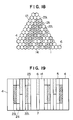
- Figs. 8 and 9 are horizontal and vertical sectional views of the second embodiment of the fast neutron reactor core of the present invention, particularly in the second cycle which is subsequent to the initial core.
- the core structures in the third and further cycles are the same as those in the first embodiment.
- Numeral 21c denotes initial core fuel assemblies which have this inner blankets, while 22c denote equilibrium core fuel assemblies which have thin inner blankets.
- the second embodiment is characterized in that the axial thickness of the internal blanket 3 is reduced to about 12 cm along the peripheral portion of the core. This features enables a further flattening of the radial power distribution in addition to the advantages offered by the first embodiment. In consequence, the maximum temperature of the cladding tubes is decreased to improve the soundness of the fuel assemblies.
- Figs. 10 and 11 are horizontal and vertical sectional views of a third embodiment of the fast neutron reactor core of the present invention, particularly in the second cycle which is subsequent to the initial core.
- the core structures in the third and further cycles are the same as those in the first embodiment.
- This embodiment as compared with the first embodiment, is characterized in that the axial thickness of some internal blanket 3 is reduced to about 12 cm which internal blanket are placed in the peripheral part of the core and which internal blanket are placed around control rods 6 inserted into the core during operation of the reactor. In three control rods 6 shown in Fig.
- the control rod 6 shown at the right side which is disposed in a peripheral portion of the core, is not intended to be inserted into the core during the reactor operation, so that the thickness of the internal blanket 3 is not decreased in this portion.
- the third embodiment offers, in addition to the advantages brought about by the first embodiment, further flattening of the power distribution in radial, circumferential and axial directions, thus attaining a further increase in the thermal margin of the reactor core.
- Figs. 12 and 13 are horizontal and vertical sectional views of a fourth embodiment of the fast neutron reactor core of the present invention, particularly in the second cycle which is subsequent to initial core.
- the core structures in the third and further cycles are the same as those in the first embodiment.
- Numeral 21d denote initial core fuel assemblies having internal blanket at their lower portions
- numeral 22d denote equilibrium core fuel assemblies having internal blanket at their lower portions.
- the fourth embodiment is characterized in that the internal blanket 3 has axial center which is about 4 cm below the axial center of the core. This arrangement enables the power distribution to be flattened when the control rods have been inserted to a half depth from the upper side of the core, thus increasing thermal margin of the core, in addition to the advantages offered by the first embodiment.
- Figs. 14 and 15 are horizontal and vertical sectional views of a fifth embodiment of the fast neutron reactor core of the present invention, particularly in the second cycle which is subsequent to the initial core.
- the core structures in the third and further cycles are the same as those in the first embodiment.
- this fifth embodiment is characterized in that the internal blanket 3 used in the first embodiment is replaced by a disk-shaped portion 8 containing a fuel of a lower plutonium enrichment than in radially or axially outer region 12.
- This disk-shaped portion 8 will be referred to as "an internal core 8".
- the internal core 8 is about 60 cm in height and about 240 cm in diameter.
- the plutonium enrichment is about 12% both in the fuel assemblies of the initial core and fuel assemblies of the equilibrium core.
- Numerals 21e and 22e respectively show initial core fuel assemblies and equilibrium core fuel assemblies both of which have internal core portions forming the internal core 8, while 21f and 22f denote initial core fuel assemblies and equilibrium core fuel assemblies which are devoid of such internal core portions. According to this arrangement, a further flattening of the axial power distribution and, hence, a greater thermal margin, are offered in addition to the advantages brought about by the first embodiment.
- Figs. 16 and 17 are horizontal and vertical sectional views of a sixth embodiment of the fast neutron reactor core of the present invention, and show the second cycle which is subsequent to the initial core.
- the core structures in the third and further cycles are the same as those in the first embodiment.
- the sixth embodiment is characterized in that the internal blanket 3 used in the first embodiment is omitted and, instead thereof, the core 1 is constituted by both an inner core portion 9 in which the plutonium enrichment of equilibrium core fuel is as low as about 16% and an outer core portion 10 in which the plutonium enrichment of equilibrium core fuel is as high as about 21%.
- the plutonium enrichment of the initial core fuel assemblies is about 15% in the inner core portion 9 and about 20% in the outer core portion 10 while the plutonium enrichment of the transition core fuel assemblies is about 25%.
- Numerals 21g and 22g denote, respectively, initial core fuel assemblies and equilibrium core fuel assemblies which form the inner core portion 9, while 21h and 22h denote, respectively, initial core fuel assemblies and equilibrium core fuel assemblies which form the outer core portion 10. This arrangement provides power distribution flattening effect substantially equivalent to that offered by the first embodiment.
- Figs. 18 and 19 are horizontal and vertical sectional views of a seventh embodiment of the fast neutron reactor core of the present invention, and show the second cycle which is subsequent to the initial core.
- the core structures in the third and further cycles are the same as those in the first embodiment.
- the sixth embodiment is characterized in that no internal blanket 3 used in the first embodiment is disposed and, instead thereof, the core 1 is constructed to have a radially heterogeneous core which is composed of both a region 13 in which the plutonium enhancement degree of the equilibrium core fuel is about 21% and an internal blanket 14 provided at the inner portion of the core with the same fuel assemblies as those forming the radial blanket.
- the plutonium enhancement degree is about 20% in the initial core fuel assemblies and about 35% in the transition core fuel assemblies.
- Numeral 21i denotes initial core fuel assemblies, while 22i denotes equilibrium core fuel assemblies. This arrangement provides power distribution flattening effect substantially equivalent to that offered by the first embodiment.
- Figs. 20 and 21 show a homogeneous core which is in the state of equilibrium core.
- the core 1 is composed of an inner core portion 9 having a comparatively low plutonium enrichment degree of about 16% and an outer core portion 10 having a comparatively high plutonium enrichment of about 21%.
- Figs. 22 and 23 show an axially heterogeneous core after a change from the homogeneous core.
- a disk-shaped internal blanket 3 which is composed mainly of depleted uranium, is disposed in the inner part of the core 1.
- the thickness of the internal blanket and the plutonium enrichment of the fuel in this blanket are the same as those of the equilibrium core in the first embodiment.
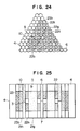
- Figs. 24 and 25 show the core configuration of an eighth embodiment of the present invention, and show a course of transition from the homogeneous core of Figs. 20 and 21 to the axially heterogeneous core shown in Figs. 22 and 23.
- the homogeneous core of Figs. 20 and 21 will be referred to as "core of 0th cycle”.
- the core shown in Figs. 24 and 25 is of a cycle subsequent to the 0th cycle and, hence, will be referred to as "core of the first transition cycle".
- This core of the first transition cycle is obtained by replacing about 1/3 of the homogeneous core fuel assemblies 22g loaded in the inner core portion 9 with axially heterogeneous core fuel assemblies 22a having internal blanket, replacing about 1/3 of the homogeneous core fuel assemblies 22h loaded in the portion of the outer core portion 109 other than the outer periphery thereof with axially heterogeneous core fuel assemblies 22b having no internal blanket, and replacing about 1/3 of the homogeneous core fuel assemblies 22h loaded in the outer peripheral portion of the outer core portion 10 with transition core fuel assemblies 23b having a plutonium enrichment of about 25%.
- Figs. 26 and 27 show the core in the second transition cycle. About 1/2 of the homogeneous core fuel assemblies 22g, 22h existed in the first transition cycle core shown in Figs. 24 and 25 has been replaced with axially heterogeneous core fuel assemblies 22a, 22b, respectively.
- Figs,. 28 and 29 show the core in the third transition cycle, in which the remainder of the homogeneous core fuel assemblies existed in the second transition cycle core of Figs. 26 and 27 has been replaced with axially heterogeneous core fuel assemblies 22a, 22b, respectively.
- the transition core fuel assemblies 23b charged in the third transition cycle core shown in Figs. 28 and 29 are replaced with axially heterogeneous core fuel assemblies 22b so that a core constitution of Figs. 22 and 23 is obtained, with the result that there is completed the transition from the homogenous core to the axially heterogeneous core.
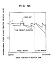
- Fig. 30 shows the radial distribution of the axial maximum linear power in the first transition cycle core of this embodiment, in comparison with a conventional arrangement in which axially heterogeneous core fuel assemblies 22a, 22b are uniformly disposed in the core 1.
- the power level is increased in the peripheral portion of the core where the neutron flux density is comparatively low, because this peripheral portion of the core is loaded with transition core fuel having high plutonium enrichment.
- the thermal power level is decreased in the radially central portion of the core. In consequence, the maximum linear power can be decreased by 5%.
- Figs. 31 and 32 are horizontal and vertical sectional views of a ninth embodiment of the fast neutron reactor core of the present invention which core is in its first transition cycle.
- the core states in the second and subsequent transition cycles are the same as those of the eighth embodiment.
- the ninth embodiment is characterized in that the axial thickness of the internal blanket 3 is reduced to about 12 cm in the peripheral portion of the blanket. This features enables a further flattening of the radial output distribution in addition to the advantages offered by the eighth embodiment. In consequence, the maximum temperature of the cladding tubes is decreased to contribute to soundness of the fuel assemblies.
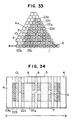
- Figs. 33 and 34 are horizontal and vertical sectional views of a tenth embodiment of the fast neutron reactor core of the present invention which core is in the first transition cycle.
- the core configuration in the second and further cycles are the same as those in the eighth embodiment.
- This embodiment is characterized in that the axial thickness of the internal blanket 3 is reduced so that the thickness of blanket portions which are disposed in the radially peripheral part of the core and which surround control rods 6 to be inserted into the core during operation of the reactor is reduced to about 12 cm. According to this arrangement, it is possible to enhance the level of the power around the control rods.
- the tenth embodiment offers, in addition to the advantages brought about by the first embodiment, further flattening of the power distribution in radial, circumferential and axial directions, thus attaining a further increase in the thermal margin of the reactor core.
- Figs. 35 and 36 are horizontal and vertical sectional views of an eleventh embodiment of the fast neutron reactor core of the present invention which core is in the first transition cycle.
- the core configuration in the second and further transition cycles are the same as those in the eighth embodiment.
- the tenth embodiment is characterized in that the internal blanket 3 has axial center which is about 4 cm below the axial center of the core. This arrangement enables flattening of the power distribution in a case where the control rods have been inserted to a half depth from the upper side of the core, thus increasing thermal margin of the core, in addition to the advantages of the eighth embodiment.
- Figs. 37 and 38 are horizontal and vertical sectional views of a twelfth embodiment of the fast neutron reactor core of the present invention which core is in the first transition cycle.
- the core structures in the second and further transition cycles are the same as those in the eighth embodiment.
- this twelfth embodiment is characterized in that the internal blanket 3 used in the first embodiment is replaced by a disk-shaped region 8, (that is, internal core 8) containing a fuel of a lower plutonium enrichment than in radially or axially outer region 12.
- the internal core 8 is about 60 cm in height and about 240 cm in diameter.
- the plutonium enrichment degree is about 12% in both the fuel assemblies initially charged and fuel assemblies used in the equilibrium core. According to this arrangement, a further flattening of the axial power distribution and, hence, a greater thermal margin, are offered in addition to the advantages brought about by the eighth embodiment.
- the neutron flux density distribution or power distribution are flattened by providing variations in the plutonium enrichment in the equilibrium core fuel assemblies and transition core fuel assemblies. It is to be understood, however, that an equivalent effect can be obtained through changing neutron infinite multiplication factor by various means such as variation in the diameter of fuel pins, pitch of the fuel pins, density of the fuel pellets,and so forth, or by omitting the wrapping tubes from some of the fuel assemblies.
- an effect of flattening the power distribution equivalent to that attained by the first embodiment can be obtained by increasing the outside diameter of each fuel pin in the transition core fuel assembly 23b of the first embodiment from 0.75 cm to 0.85 cm, while increasing the volume fraction of the fuel from about 41% to about 45%.
- the fast neutron reactor core of the invention and the fuel renewing method of the invention enable about 5% increase in the thermal margin without increasing the number of fuel assemblies to be replaced in one cycle, as compared with the prior art, thus offering a corresponding reduction in the fuel cycle cost. Furthermore, since the excess reactivity of the core can be maintained, it is possible to prevent any reduction in the rate of operation of the nuclear reactor which reduction occurs due to the shortening of the operation period in the transition cycle.
Landscapes
- Physics & Mathematics (AREA)
- Engineering & Computer Science (AREA)
- Plasma & Fusion (AREA)
- General Engineering & Computer Science (AREA)
- High Energy & Nuclear Physics (AREA)
- Monitoring And Testing Of Nuclear Reactors (AREA)
- Production Of Liquid Hydrocarbon Mixture For Refining Petroleum (AREA)
Applications Claiming Priority (2)
| Application Number | Priority Date | Filing Date | Title |
|---|---|---|---|
| JP1063850A JP2786656B2 (ja) | 1989-03-17 | 1989-03-17 | 高速炉の炉心及び燃料交換方法 |
| JP63850/89 | 1989-03-17 |
Publications (2)
| Publication Number | Publication Date |
|---|---|
| EP0387891A2 true EP0387891A2 (fr) | 1990-09-19 |
| EP0387891A3 EP0387891A3 (fr) | 1991-01-02 |
Family
ID=13241220
Family Applications (1)
| Application Number | Title | Priority Date | Filing Date |
|---|---|---|---|
| EP19900104983 Withdrawn EP0387891A3 (fr) | 1989-03-17 | 1990-03-16 | Réacteur à neutrons rapides et procédé pour le ravitaillement de combustible |
Country Status (2)
| Country | Link |
|---|---|
| EP (1) | EP0387891A3 (fr) |
| JP (1) | JP2786656B2 (fr) |
Cited By (3)
| Publication number | Priority date | Publication date | Assignee | Title |
|---|---|---|---|---|
| CN102194531A (zh) * | 2010-03-11 | 2011-09-21 | 中国核动力研究设计院 | 快中子反应堆燃料双行波自分区燃烧方法 |
| CN109545397A (zh) * | 2018-10-23 | 2019-03-29 | 中广核研究院有限公司 | 一种纳冷快堆堆芯结构 |
| CN115547525A (zh) * | 2022-10-08 | 2022-12-30 | 华能核能技术研究院有限公司 | 球床式高温气冷堆首次装料及初始临界方法及装置 |
Family Cites Families (2)
| Publication number | Priority date | Publication date | Assignee | Title |
|---|---|---|---|---|
| US2870076A (en) * | 1956-07-31 | 1959-01-20 | Leonard J Koch | Method and apparatus for improving performance of a fast reactor |
| US4050985A (en) * | 1974-09-13 | 1977-09-27 | Westinghouse Electric Corporation | Nuclear reactor |
-
1989
- 1989-03-17 JP JP1063850A patent/JP2786656B2/ja not_active Expired - Fee Related
-
1990
- 1990-03-16 EP EP19900104983 patent/EP0387891A3/fr not_active Withdrawn
Cited By (3)
| Publication number | Priority date | Publication date | Assignee | Title |
|---|---|---|---|---|
| CN102194531A (zh) * | 2010-03-11 | 2011-09-21 | 中国核动力研究设计院 | 快中子反应堆燃料双行波自分区燃烧方法 |
| CN109545397A (zh) * | 2018-10-23 | 2019-03-29 | 中广核研究院有限公司 | 一种纳冷快堆堆芯结构 |
| CN115547525A (zh) * | 2022-10-08 | 2022-12-30 | 华能核能技术研究院有限公司 | 球床式高温气冷堆首次装料及初始临界方法及装置 |
Also Published As
| Publication number | Publication date |
|---|---|
| JPH02243992A (ja) | 1990-09-28 |
| JP2786656B2 (ja) | 1998-08-13 |
| EP0387891A3 (fr) | 1991-01-02 |
Similar Documents
| Publication | Publication Date | Title |
|---|---|---|
| EP0691657A1 (fr) | Coeur pour réacteur refroidi à l'eau légère, assemblage combustible et barre de commande | |
| EP2088600A1 (fr) | Coeur de réacteur à eau bouillante | |
| JP2000019280A (ja) | 軽水冷却型原子炉の炉心および同原子炉の運転方法 | |
| JP2020003244A (ja) | 高速炉の炉心 | |
| US20090196392A1 (en) | Core Of A Boiling Water Reactor | |
| JP2772061B2 (ja) | 燃料集合体 | |
| JP2510612B2 (ja) | 原子炉の炉心及び原子炉の初装荷炉心 | |
| EP0387891A3 (fr) | Réacteur à neutrons rapides et procédé pour le ravitaillement de combustible | |
| JP2010145140A (ja) | 高速炉の燃料装荷方法 | |
| JP3514869B2 (ja) | 沸騰水型原子炉用燃料集合体 | |
| JP2886555B2 (ja) | 沸騰水型原子炉用燃料集合体 | |
| JP2972177B2 (ja) | 熱中性子炉用燃料要素及び燃料集合体 | |
| JP3339768B2 (ja) | 軽水型原子炉炉心 | |
| JP3318210B2 (ja) | Mox燃料集合体及び炉心 | |
| JP3485956B2 (ja) | 原子炉炉心およびその燃料集合体 | |
| JP2550136B2 (ja) | 高速増殖炉の炉心及び高速増殖炉の燃料装荷方法 | |
| JP3943624B2 (ja) | 燃料集合体 | |
| JP4351798B2 (ja) | 燃料集合体および原子炉 | |
| JP3031644B2 (ja) | 燃料集合体及び炉心 | |
| JP3884192B2 (ja) | Mox燃料集合体及び原子炉の炉心並びに原子炉の運転方法 | |
| JP2005098924A (ja) | Mox燃料集合体 | |
| JPH0827370B2 (ja) | 沸騰水型原子炉 | |
| JPH09304566A (ja) | 原子炉燃料要素及び燃料集合体 | |
| JPH04238292A (ja) | 沸騰水型原子炉 | |
| JPS61147184A (ja) | 燃料集合体 |
Legal Events
| Date | Code | Title | Description |
|---|---|---|---|
| PUAI | Public reference made under article 153(3) epc to a published international application that has entered the european phase |
Free format text: ORIGINAL CODE: 0009012 |
|
| AK | Designated contracting states |
Kind code of ref document: A2 Designated state(s): DE FR GB NL |
|
| PUAL | Search report despatched |
Free format text: ORIGINAL CODE: 0009013 |
|
| AK | Designated contracting states |
Kind code of ref document: A3 Designated state(s): DE FR GB NL |
|
| 17P | Request for examination filed |
Effective date: 19901127 |
|
| 17Q | First examination report despatched |
Effective date: 19930504 |
|
| STAA | Information on the status of an ep patent application or granted ep patent |
Free format text: STATUS: THE APPLICATION HAS BEEN WITHDRAWN |
|
| 18W | Application withdrawn |
Withdrawal date: 19940412 |