EP0387964B1 - Système de suspension pour panneaux de faux plafond et profilé pour ce système - Google Patents
Système de suspension pour panneaux de faux plafond et profilé pour ce système Download PDFInfo
- Publication number
- EP0387964B1 EP0387964B1 EP90200598A EP90200598A EP0387964B1 EP 0387964 B1 EP0387964 B1 EP 0387964B1 EP 90200598 A EP90200598 A EP 90200598A EP 90200598 A EP90200598 A EP 90200598A EP 0387964 B1 EP0387964 B1 EP 0387964B1
- Authority
- EP
- European Patent Office
- Prior art keywords
- sectional
- tubular part
- suspension
- sectional bar
- bars
- Prior art date
- Legal status (The legal status is an assumption and is not a legal conclusion. Google has not performed a legal analysis and makes no representation as to the accuracy of the status listed.)
- Expired - Lifetime
Links
- 239000000725 suspension Substances 0.000 title claims abstract description 38
- 238000003780 insertion Methods 0.000 claims abstract description 12
- 230000037431 insertion Effects 0.000 claims abstract description 12
- 239000000463 material Substances 0.000 claims description 2
- 230000004308 accommodation Effects 0.000 abstract 1
- 230000015572 biosynthetic process Effects 0.000 description 3
- 239000002184 metal Substances 0.000 description 2
- 230000001154 acute effect Effects 0.000 description 1
- 238000010276 construction Methods 0.000 description 1
- 238000004519 manufacturing process Methods 0.000 description 1
- 238000012986 modification Methods 0.000 description 1
- 230000004048 modification Effects 0.000 description 1
- 230000000284 resting effect Effects 0.000 description 1
Images

Classifications
-
- E—FIXED CONSTRUCTIONS
- E04—BUILDING
- E04B—GENERAL BUILDING CONSTRUCTIONS; WALLS, e.g. PARTITIONS; ROOFS; FLOORS; CEILINGS; INSULATION OR OTHER PROTECTION OF BUILDINGS
- E04B9/00—Ceilings; Construction of ceilings, e.g. false ceilings; Ceiling construction with regard to insulation
- E04B9/06—Ceilings; Construction of ceilings, e.g. false ceilings; Ceiling construction with regard to insulation characterised by constructional features of the supporting construction, e.g. cross section or material of framework members
- E04B9/065—Ceilings; Construction of ceilings, e.g. false ceilings; Ceiling construction with regard to insulation characterised by constructional features of the supporting construction, e.g. cross section or material of framework members comprising supporting beams having a folded cross-section
- E04B9/067—Ceilings; Construction of ceilings, e.g. false ceilings; Ceiling construction with regard to insulation characterised by constructional features of the supporting construction, e.g. cross section or material of framework members comprising supporting beams having a folded cross-section with inverted T-shaped cross-section
- E04B9/068—Ceilings; Construction of ceilings, e.g. false ceilings; Ceiling construction with regard to insulation characterised by constructional features of the supporting construction, e.g. cross section or material of framework members comprising supporting beams having a folded cross-section with inverted T-shaped cross-section with double web
-
- E—FIXED CONSTRUCTIONS
- E04—BUILDING
- E04B—GENERAL BUILDING CONSTRUCTIONS; WALLS, e.g. PARTITIONS; ROOFS; FLOORS; CEILINGS; INSULATION OR OTHER PROTECTION OF BUILDINGS
- E04B9/00—Ceilings; Construction of ceilings, e.g. false ceilings; Ceiling construction with regard to insulation
- E04B9/06—Ceilings; Construction of ceilings, e.g. false ceilings; Ceiling construction with regard to insulation characterised by constructional features of the supporting construction, e.g. cross section or material of framework members
- E04B9/12—Connections between non-parallel members of the supporting construction
- E04B9/127—Connections between non-parallel members of the supporting construction one member being discontinuous and abutting against the other member
-
- E—FIXED CONSTRUCTIONS
- E04—BUILDING
- E04B—GENERAL BUILDING CONSTRUCTIONS; WALLS, e.g. PARTITIONS; ROOFS; FLOORS; CEILINGS; INSULATION OR OTHER PROTECTION OF BUILDINGS
- E04B9/00—Ceilings; Construction of ceilings, e.g. false ceilings; Ceiling construction with regard to insulation
- E04B9/18—Means for suspending the supporting construction
-
- E—FIXED CONSTRUCTIONS
- E04—BUILDING
- E04B—GENERAL BUILDING CONSTRUCTIONS; WALLS, e.g. PARTITIONS; ROOFS; FLOORS; CEILINGS; INSULATION OR OTHER PROTECTION OF BUILDINGS
- E04B9/00—Ceilings; Construction of ceilings, e.g. false ceilings; Ceiling construction with regard to insulation
- E04B9/06—Ceilings; Construction of ceilings, e.g. false ceilings; Ceiling construction with regard to insulation characterised by constructional features of the supporting construction, e.g. cross section or material of framework members
- E04B2009/062—Caps covering visible surfaces of the supporting construction
-
- E—FIXED CONSTRUCTIONS
- E04—BUILDING
- E04B—GENERAL BUILDING CONSTRUCTIONS; WALLS, e.g. PARTITIONS; ROOFS; FLOORS; CEILINGS; INSULATION OR OTHER PROTECTION OF BUILDINGS
- E04B9/00—Ceilings; Construction of ceilings, e.g. false ceilings; Ceiling construction with regard to insulation
- E04B9/18—Means for suspending the supporting construction
- E04B2009/186—Means for suspending the supporting construction with arrangements for damping vibration
Definitions
- the invention relates to a suspension system for ceiling panels, according to the preamble of claim 1.
- a suspension system of this type is known from DE-A-1 021 555. Said known system does not show any means for suspending the grid or frame assembly to the existing ceiling structure. Further the connecting elements as well as the sectional bars have a rather complicated configuration and are therefore difficult to manufacture.
- AU-B-492 623 discloses a suspended ceiling system having main support beams and intermediate support beams.
- the main support beams have an upper hollow tubular part, the upper wall thereof having slots at regular intervals.
- Said main beams are suspended by means of quick-connection support clips.
- Said clips are inserted through the slots in said upper wall of the tubular part and lock therein by angular displaced tabs provided in the main body of the support clip. In this way a kind of snap connection is provided, which is very unreliable and not suitable for heavy loads.
- GB-PS-1 400 050 discloses a suspended ceiling system, wherein the supporting rail comprises a substantially U-shaped channel the free edges of which are bent inwardly to form a pair of ledges. Each of the ledges is provided with a row of slots.
- the supporting rail is suspended by means of a suspension device having hooks which pass through the slots and engage under the respective ledge.
- the supporting rail of this specification is of another kind and does not have an upper hollow tubular part. So the means for suspending the rail
- the object of the present invention is now to provide a suspension system for ceiling panels which is cheap to produce, in which the sectional bars are easily and quickly connected to each other, and in which the suspension elements as well as the connecting elements do not constitute any hindrance when the ceiling panels are being placed in the supporting grid.
- This arrangement has the advantage that the tubular part of the web portion serves to accommodate the hooked suspension elements, so that the hook portions of the suspension elements are essentially housed in said tubular part and thus are directed in the lengthwise direction of the sectional bars. These hook portions thus constitute no hindrance at all when the ceiling panels are being fitted.
- a further advantage is that in this way the suspension element is securely connected to the rod, and the suspension element can easily be displaced relatively to the rod until the necessary height for the sectional bar has been set.
- the invention provides for a connecting element which is accommodated with its insertion part in the tubular part of one sectional bar and is provided with a supporting part which projects beyond said sectional bar and rests against the other sectional bar and has a hooked lip which is designed to engage in an aperture provided in the top side of the tubular part of the other sectional bar, in such a way that the side flanges of the two sectional bars are coplanar with each other and abut to each other with a right angle.
- the hooked lip of the connecting element is according to the invention displaced to one side relative to the vertical longitudinal centre face of the sectional bar in which it is accommodated with its insertion part.
- the supporting part of the connecting element according to the invention is provided with at least one laterally directed supporting face which after fitting rests against the part of the body part of the sectional bar lying below the tubular part and in which the hooked lip also engages.
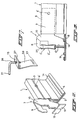
- the sectional bar 1 shown partially and in perspective in Fig. 1 is in general the shape of an inverted T, with a web portion 2 which in the fitted position shown is positioned vertically and at the top side comprises a hollow tubular part 3.
- the tubular part is elongated in shape with walls curved slightly inwards. Apertures, the purpose of which will be explained later, are provided in the top wall of the tubular part.
- the sectional bar is roll-formed from sheet material which in the web portion is folded together leaving free the top tubular part 3, and then at the bottom side is flanged with a right angle to both sides to form side flanges 4, 5 on which the ceiling panels come to rest.
- the side flanges 4, 5 are covered at the bottom side by a covering strip 6, in order to give the sectional bar a smooth appearance when fitted.
- sectional bars are designed to form a supporting grid with rectangular or square apertures.
- the supporting grid is suspended by means of suspension elements from an existing ceiling structure, and the apertures in the grid are then filled up with ceiling panels (not shown), which rest on the above-mentioned side flanges.
- a first connecting element 7, which is designed to form a right-angled T-connection between two sectional bars is shown in Figs. 2 and 3.
- the connecting element 7 is fixed at the end of a sectional bar 1 by means of an insertion part 8 inserted into the hollow tubular part 3 of the sectional bar.
- the insertion part 8 is of such dimensions that it fits without excessive play into the tubular part, while the inwardly curved side walls of said part exert a clamping action on the insertion part.
- the insertion part 8 is also provided with an aperture 9 which serves to secure the connecting element in the sectional bar 1. This is carried out by providing depressions in the tubular part of the sectional bar from the outside at the level of the aperture 9 using a suitable tool, said depressions engaging with the aperture 9 and fixing the connecting element.
- the part of the fixing element projecting beyond the sectional bar 1 is formed by a supporting element 10 which at the top side is provided with a hooked lip 11.
- the supporting part lies against the web portion and against a side flange of a second sectional bar 1' placed at right angles to the sectional bar 1 and to be connected thereto, while the hooked lip 11 engages in an aperture provided at the top side of the tubular part 3' of the sectional bar 1'.
- the supporting part 10 is provided with two supporting faces 12, 13 which are at right angles thereto and rest against the part of the body part of the sectional bar 1' lying below the tubular part 3'.
- the side flanges 4 and 5 of each sectional bar are provided with a ridge 14 running in the lengthwise direction, which mates with a recess 15 formed on the bottom edge of the supporting part 10, in order to fix the sectional bar 1' in such a way relative to the sectional bar 1 that the side flanges of the two sectional bars abut accurately against each other.
- the recess 15 together with the ridge 14 constitute a snap-connection.
- the connecting element 7 comprises two plate-shaped parts which are placed against each other and connected to each other, and which, with the exception of the hooked lip 11, are identical in shape and are mirror symmetrical relative to the supporting faces 12 and 13.
- This configuration means that the hooked lip 11 is displaced sideways relative to the central longitudinal plane of symmetry of the sectional bar 1.
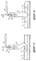
- Fig. 4 shows a top view of an intersection formed by the sectional bars with one continuous sectional bar 1 and on either side thereof a sectional bar 1' and 1'' connecting at right angles thereto.
- the lips 11' and 11'' of the connecting elements 7' and 7'' connected to the bars 1' and 1'' in this case lie next to each other and engage in the same aperture of the sectional bar 1, while the sectional bars 1' and 1'' lie accurately in line with each other.
- Fig. 5 shows a longitudinal section of a sectional bar 1 with a suspension element 16 fitted therein.
- the suspension element which is made of sheet metal comprises a hook portion 17 which engages in two apertures spaced apart in the top wall of the tubular part 3 of the sectional bar 1.
- the hook portion lies in the lengthwise direction of the sectional bar 1, and the hook portion 17 is essentially accommodated inside the tubular part 3.
- the suspension element 16 is connected by means of a pressure connection to a rod 18, which is in turn connected to an existing ceiling structure.
- the suspension element 16 has at the top end a horizontal face 19 and has a threaded aperture into which an externally threaded arm 20 of an operating lever 21 is screwed.
- the externally threaded arm 20 is provided with a recess or a flattened side 26 which together with a recess 27 in the threaded aperture in the face 19 leaves sufficient space for pushing through the rod 18 (see also Fig. 7).
- the lever 20 is turned, the rod 18 is clamped, in which case the external screw thread of the arm 20 cuts into the rod 18 and in this way produces a firm connection between the rod 18 and the connecting element, said connection being capable of withstanding impacts and vibrations.
- the horizontal face 19 merges via an acute angle into a sloping face 28 which in turn merges in the vertical hook portion 17.
- the connecting element is somewhat resilient in the vertical direction which has the advantage that vibrations and impacts do not affect the pressure connection between the rod 18 and the suspension element.
- Fig. 6 shows another connecting element 22 which is designed to connect together two sectional bars 1 and 1' in the lengthwise direction.
- the connecting element 22 is to this end provided with two insertion parts 8 which lie in line with each other and are each provided with an aperture 9.
- the two sectional bars 1 and 1' are pushed on either side onto the appropriate insertion parts 8 until the sectional bars 1 and 1' are resting against each other.
- depressions 9' are then made in the sectional bars from the outside at the level of the apertures 9, in order to fix the sectional bars to the connecting element.
- the connecting element 22 is combined with a suspension element of the type described above with reference to Fig. 5.
- a group of three apertures is provided in the top side of the tubular part 3. Such groups are provided at regular intervals from each other along the length of the sectional bars.
- the outermost apertures 23 and 24 are designed to accommodate the hook portion 17 of a suspension element 16, while the smaller central apertures 24 are for accommodating the hooked lips 11 of the connecting elements 7 (see also Fig. 4). It will be clear that these apertures can be provided at the factory. If necessary, apertures can be provided in the sectional bars at the other points for instance by using a file, so that the supporting grid can easily be adapted to local conditions.
- the suspension system according to the invention is of a considerably lighter and more rigid construction than the existing systems.
- the sectional bars can easily be adapted to the local circumstances, and the connecting elements as well as the suspension elements are easily and cheap to manufactore from sheet metal.
- the most important advantage is, however, that the suspension system is much quicker and easier to fit.
- the connecting element exists of a single plate-part, in which case said connecting element comprises only one supporting face and the hooked lip 11 is slightly bent sidewards.
Landscapes
- Engineering & Computer Science (AREA)
- Architecture (AREA)
- Physics & Mathematics (AREA)
- Electromagnetism (AREA)
- Civil Engineering (AREA)
- Structural Engineering (AREA)
- Mutual Connection Of Rods And Tubes (AREA)
- Joining Of Building Structures In Genera (AREA)
- Residential Or Office Buildings (AREA)
- Load-Engaging Elements For Cranes (AREA)
- Conveying And Assembling Of Building Elements In Situ (AREA)
Claims (5)
- Système de suspension pour panneaux de plafond, comprenant une grille de support formée de barres profilées interconnectées (1,1',1'') qui se recoupent entre elles à angle droit, ladite grille étant supportée à une certaine distance au-dessous d'une structure existante d'un plafond, lesdites barres profilées possédant une partie formant âme verticale (2), qui possède, à son extrémité inférieure, des deux côtés d'elle-même, des brides latérales horizontales (4,5) servant à supporter les panneaux de plafond, la partie formant âme de l'une desdites barres profilées possédant, à son extrémité supérieure, une partie tubulaire creuse (3), et les barres profilées étant raccordées entre elles au moyen d'éléments de raccordement (7) possédant chacun au moins un élément d'insertion (8) devant être logé dans la partie tubulaire de ladite barre profilée, caractérisé en ce que la partie tubulaire possède une forme allongée, lorsqu'on regarde dans la direction verticale de la partie formant âme, lesdites barres profilées sont suspendues à des intervalles réguliers à l'aide d'éléments de suspension (16), dont chacun possède une partie formant crochet, lesdits éléments de suspension ainsi que les éléments de raccordement étant formés par un matériau en forme de feuille, et la partie tubulaire creuse possédant une paroi supérieure dans laquelle sont ménagées deux ouvertures espacées (23,24) disposées sur l'étendue en longueur de la barre profilée de manière à recevoir l'une desdites parties formant crochet de sorte que la partie formant crochet est logée à l'intérieur de ladite partie tubulaire creuse, les éléments de suspension étant raccordés à une tige (18) qui à son tour est raccordée à la structure du plafond, chacun des éléments de suspension comporte, à l'extrémité supérieure, une face d'extrémité horizontale dans laquelle est ménagée une ouverture taraudée, dans laquelle est vissé un bras fileté extérieurement (20) d'un levier d'actionnement (21), ledit bras étant pourvu d'un renfoncement (26) qui, conjointement avec un renfoncement (27) ménagé dans l'ouverture taraudée, laisse subsister un espace suffisant pour qu'on puisse y repousser ladite barre (18) de manière à serrer cette dernière en faisant tourner ledit bras.
- Système de suspension selon la revendication 1, caractérisé en ce que la partie d'insertion dudit élément de raccordement servant à établir une liaison à angle droit entre deux barres profilées est logée dans une partie tubulaire d'une barre profilée et possède en outre un élément de support (10), qui fait saillie au-delà de ladite barre profilée et, dans la position adaptée, est en appui contre la partie formant âme de l'autre barre profilée, et comporte une lèvre crochue (11) qui s'engage dans une ouverture (25) ménagée dans la paroi supérieure de la partie tubulaire de ladite autre barre profilée.
- Système de suspension selon la revendication 2, caractérisé en ce que la partie de support de l'élément de raccordement comporte au moins une face de support (12,13) dirigée latéralement et qui, après montage, est en appui contre l'élément de la partie formant âme de l'autre barre profilée, qui est situé au-dessous de la partie tubulaire, dans laquelle s'engage également la lèvre crochue (11).
- Système de suspension selon la revendication 2 ou 3, caractérisé en ce que la lèvre crochue de chaque élément de raccordement est décalée d'un côté par rapport à la face centrale longitudinale verticale de la barre profilée, dans laquelle est logée au moyen de sa partie d'insertion.
- Système de suspension selon la revendication 1, caractérisé en ce que la face d'extrémité horizontale (16) de l'élément de suspension se raccorde, par une surface oblique (28), à la partie verticale (17) du crochet dudit élément.
Priority Applications (1)
| Application Number | Priority Date | Filing Date | Title |
|---|---|---|---|
| AT90200598T ATE97712T1 (de) | 1989-03-16 | 1990-03-13 | Aufhaengeeinrichtung fuer deckenplatten und profilstab fuer eine solche einrichtung. |
Applications Claiming Priority (2)
| Application Number | Priority Date | Filing Date | Title |
|---|---|---|---|
| NL8900651 | 1989-03-16 | ||
| NL8900651A NL8900651A (nl) | 1989-03-16 | 1989-03-16 | Ophangsysteem voor plafondplaten alsmede een profiel voor een dergelijk systeem. |
Publications (2)
| Publication Number | Publication Date |
|---|---|
| EP0387964A1 EP0387964A1 (fr) | 1990-09-19 |
| EP0387964B1 true EP0387964B1 (fr) | 1993-11-24 |
Family
ID=19854302
Family Applications (1)
| Application Number | Title | Priority Date | Filing Date |
|---|---|---|---|
| EP90200598A Expired - Lifetime EP0387964B1 (fr) | 1989-03-16 | 1990-03-13 | Système de suspension pour panneaux de faux plafond et profilé pour ce système |
Country Status (6)
| Country | Link |
|---|---|
| US (1) | US5076036A (fr) |
| EP (1) | EP0387964B1 (fr) |
| AT (1) | ATE97712T1 (fr) |
| CA (1) | CA2012068A1 (fr) |
| DE (1) | DE69004716D1 (fr) |
| NL (1) | NL8900651A (fr) |
Families Citing this family (14)
| Publication number | Priority date | Publication date | Assignee | Title |
|---|---|---|---|---|
| NL9002427A (nl) * | 1990-11-08 | 1992-06-01 | Karel Kuiper | Ophanghaak. |
| GB2286836B (en) * | 1994-02-23 | 1998-07-08 | Nigel Edward Fuller | Ceiling grids |
| EP1233115A1 (fr) * | 2001-02-16 | 2002-08-21 | Pietro Sacco | Elément de construction pour l'installation des planchers en combinaison avec des panneaux en matériel de mousse |
| CA2354618C (fr) * | 2001-08-01 | 2006-03-14 | Groupe Canam Inc. / Canam Group Inc. | Pied de poutrelle modulaire |
| US6722098B2 (en) * | 2002-02-21 | 2004-04-20 | Worthington Armstrong Venture | Beam for drywall ceiling |
| DE60310652T2 (de) * | 2002-07-30 | 2007-10-04 | Hunter Douglas Industries B.V. | Paneelaufbau für abgehängte Decken |
| US6779315B1 (en) * | 2003-05-15 | 2004-08-24 | Vincent J. Bongio | Suspended ceiling/raised floor connection system |
| US20080155934A1 (en) * | 2006-12-29 | 2008-07-03 | Usg Interiors, Inc. | Easy cut suspension grid |
| USD668352S1 (en) | 2008-01-11 | 2012-10-02 | Usg Interiors, Llc | Suspended ceiling wall angle |
| GB2456328A (en) | 2008-01-11 | 2009-07-15 | Usg Interiors Inc | Grid members for a suspended ceiling and methods of making same |
| EP2735662B1 (fr) * | 2012-11-27 | 2017-07-26 | Saint-Gobain Ecophon AB | Structure de support et système de plafond suspendu comprenant une telle structure de support |
| PL235058B1 (pl) * | 2017-05-30 | 2020-05-18 | Szymanski Andrzej Lars | Profil z listwą łącznikową do mocowania elementów sufitu podwieszanego |
| CN112267612B (zh) * | 2020-10-27 | 2021-11-16 | 北京华邑建设集团有限公司 | 一种大跨度金属天棚龙骨安装结构 |
| BE1031215B1 (nl) | 2022-12-29 | 2024-07-29 | Ursus Bv | Een onzichtbare ophanginrichting |
Family Cites Families (12)
| Publication number | Priority date | Publication date | Assignee | Title |
|---|---|---|---|---|
| DE1021555B (de) * | 1956-03-27 | 1957-12-27 | Wilhelm Baecker | An einer tragenden Konstruktion aufgehaengte Zwischendecke mit Haupt- und Nebentraegern |
| FR1180949A (fr) * | 1957-08-08 | 1959-06-10 | Ateliers De Const Metalliques | Système de montage d'une sous-toiture |
| US3232021A (en) * | 1961-03-15 | 1966-02-01 | Wilson Bertram Arnold | Ceiling structure |
| US3334465A (en) * | 1965-09-09 | 1967-08-08 | Certain Teed Prod Corp | Furring clip and flush runner assembly |
| GB1198441A (en) * | 1966-07-22 | 1970-07-15 | Donald Mcknight | Improvements in relation to Ceilings |
| AU1209866A (en) * | 1967-09-27 | 1969-04-03 | Ceiling suspension means | |
| US3596425A (en) * | 1970-02-20 | 1971-08-03 | Keene Building Products Corp | Ceiling tile support grid system |
| DE2146528C3 (de) * | 1971-09-17 | 1975-05-28 | Richter, Reinhold, Dipl.-Ing., 6100 Darmstadt | Traggerippe für eine Unterdecke |
| AU492623B1 (en) * | 1974-04-03 | 1976-09-09 | K.H. Stramit Corporation Limited | A suspended ceiling system |
| US4206578A (en) * | 1978-07-31 | 1980-06-10 | Donn Incorporated | Grid tee for suspension ceilings or the like |
| US4479341A (en) * | 1982-04-02 | 1984-10-30 | Fastway Fasteners, Inc. | Clips for T-bar grid ceiling arrangement |
| US4520609A (en) * | 1982-09-27 | 1985-06-04 | Donn Incorporated | Grid tee for suspension ceilings or the like |
-
1989
- 1989-03-16 NL NL8900651A patent/NL8900651A/nl not_active Application Discontinuation
-
1990
- 1990-03-13 CA CA002012068A patent/CA2012068A1/fr not_active Abandoned
- 1990-03-13 EP EP90200598A patent/EP0387964B1/fr not_active Expired - Lifetime
- 1990-03-13 AT AT90200598T patent/ATE97712T1/de not_active IP Right Cessation
- 1990-03-13 DE DE90200598T patent/DE69004716D1/de not_active Expired - Lifetime
- 1990-03-14 US US07/493,515 patent/US5076036A/en not_active Expired - Fee Related
Also Published As
| Publication number | Publication date |
|---|---|
| US5076036A (en) | 1991-12-31 |
| DE69004716D1 (de) | 1994-01-05 |
| ATE97712T1 (de) | 1993-12-15 |
| EP0387964A1 (fr) | 1990-09-19 |
| CA2012068A1 (fr) | 1990-09-16 |
| NL8900651A (nl) | 1990-10-16 |
Similar Documents
| Publication | Publication Date | Title |
|---|---|---|
| EP0801257B1 (fr) | Dispositif universel de suspension à une poutre | |
| US5100086A (en) | Cable tray support system | |
| US4811539A (en) | Wall framing system | |
| US3677589A (en) | Field installation clip for exposed grid systems | |
| US4448004A (en) | Channel and cut-out structure for removeable partition wall | |
| US3596425A (en) | Ceiling tile support grid system | |
| US4895331A (en) | Shelf bracket | |
| US5076036A (en) | Suspension system for ceiling panels, and a sectional bar for such a system | |
| US5003740A (en) | Open office system partition panel assembly | |
| US3329387A (en) | Support assembly for fixtures or the like | |
| US4665674A (en) | Grid ceiling | |
| US4760677A (en) | Suspended ceiling having a concealed suspension grid and lay-in metal panels supported thereon | |
| US4364215A (en) | Suspended ceiling assembly and stabilizer bar therefor | |
| US4674240A (en) | Wall panel system | |
| US20070130869A1 (en) | Suspended ceiling segment | |
| KR19980032561A (ko) | 클린 룸 커버, 바람직하게는 스크린 천정 | |
| US5423507A (en) | Bracket for holding ceiling suspended fixtures | |
| JPS61231818A (ja) | 母線ホルダー装置 | |
| US4549375A (en) | Ceiling construction | |
| US4114326A (en) | Fixture hanging assembly | |
| US5228263A (en) | T-bar partition support clip | |
| US4696141A (en) | Suspended ceiling having a concealed suspension grid and lay-in metal panels supported thereon | |
| US4494346A (en) | Ceiling system and panel-securing device therefor | |
| US4464876A (en) | Suspended woodbeam ceiling construction | |
| SK7152002A3 (en) | Holding device for holding long objects, especially roof drainage gutters, which are to be attached to a building |
Legal Events
| Date | Code | Title | Description |
|---|---|---|---|
| PUAI | Public reference made under article 153(3) epc to a published international application that has entered the european phase |
Free format text: ORIGINAL CODE: 0009012 |
|
| AK | Designated contracting states |
Kind code of ref document: A1 Designated state(s): AT BE CH DE DK ES FR GB GR IT LI LU NL SE |
|
| 17P | Request for examination filed |
Effective date: 19910313 |
|
| 17Q | First examination report despatched |
Effective date: 19910920 |
|
| GRAA | (expected) grant |
Free format text: ORIGINAL CODE: 0009210 |
|
| AK | Designated contracting states |
Kind code of ref document: B1 Designated state(s): AT BE CH DE DK ES FR GB GR IT LI LU NL SE |
|
| PG25 | Lapsed in a contracting state [announced via postgrant information from national office to epo] |
Ref country code: IT Free format text: LAPSE BECAUSE OF FAILURE TO SUBMIT A TRANSLATION OF THE DESCRIPTION OR TO PAY THE FEE WITHIN THE PRE;WARNING: LAPSES OF ITALIAN PATENTS WITH EFFECTIVE DATE BEFORE 2007 MAY HAVE OCCURRED AT ANY TIME BEFORE 2007. THE CORRECT EFFECTIVE DATE MAY BE DIFFERENT FROM THE ONE RECORDED.SCRIBED TIME-LIMIT Effective date: 19931124 Ref country code: AT Effective date: 19931124 Ref country code: GR Free format text: LAPSE BECAUSE OF FAILURE TO SUBMIT A TRANSLATION OF THE DESCRIPTION OR TO PAY THE FEE WITHIN THE PRESCRIBED TIME-LIMIT Effective date: 19931124 Ref country code: BE Effective date: 19931124 Ref country code: NL Effective date: 19931124 Ref country code: DK Effective date: 19931124 Ref country code: DE Effective date: 19931124 Ref country code: FR Effective date: 19931124 Ref country code: LI Effective date: 19931124 Ref country code: ES Free format text: THE PATENT HAS BEEN ANNULLED BY A DECISION OF A NATIONAL AUTHORITY Effective date: 19931124 Ref country code: SE Effective date: 19931124 Ref country code: CH Effective date: 19931124 |
|
| REF | Corresponds to: |
Ref document number: 97712 Country of ref document: AT Date of ref document: 19931215 Kind code of ref document: T |
|
| REF | Corresponds to: |
Ref document number: 69004716 Country of ref document: DE Date of ref document: 19940105 |
|
| REG | Reference to a national code |
Ref country code: CH Ref legal event code: PL |
|
| PG25 | Lapsed in a contracting state [announced via postgrant information from national office to epo] |
Ref country code: GB Effective date: 19940313 |
|
| PG25 | Lapsed in a contracting state [announced via postgrant information from national office to epo] |
Ref country code: LU Free format text: LAPSE BECAUSE OF NON-PAYMENT OF DUE FEES Effective date: 19940331 |
|
| EN | Fr: translation not filed | ||
| NLV1 | Nl: lapsed or annulled due to failure to fulfill the requirements of art. 29p and 29m of the patents act | ||
| PLBE | No opposition filed within time limit |
Free format text: ORIGINAL CODE: 0009261 |
|
| STAA | Information on the status of an ep patent application or granted ep patent |
Free format text: STATUS: NO OPPOSITION FILED WITHIN TIME LIMIT |
|
| GBPC | Gb: european patent ceased through non-payment of renewal fee |
Effective date: 19940313 |
|
| 26N | No opposition filed |