EP0388024A1 - Dispositif de connexion pour câble d'allumage - Google Patents
Dispositif de connexion pour câble d'allumage Download PDFInfo
- Publication number
- EP0388024A1 EP0388024A1 EP90301743A EP90301743A EP0388024A1 EP 0388024 A1 EP0388024 A1 EP 0388024A1 EP 90301743 A EP90301743 A EP 90301743A EP 90301743 A EP90301743 A EP 90301743A EP 0388024 A1 EP0388024 A1 EP 0388024A1
- Authority
- EP
- European Patent Office
- Prior art keywords
- ignition
- ignition cable
- elongated pipe
- terminal
- head cover
- Prior art date
- Legal status (The legal status is an assumption and is not a legal conclusion. Google has not performed a legal analysis and makes no representation as to the accuracy of the status listed.)
- Granted
Links
- 239000004033 plastic Substances 0.000 claims abstract description 9
- 238000002485 combustion reaction Methods 0.000 claims description 4
- 239000000463 material Substances 0.000 claims description 3
- 230000002787 reinforcement Effects 0.000 claims description 2
- 230000003014 reinforcing effect Effects 0.000 claims description 2
- 230000000712 assembly Effects 0.000 description 2
- 238000000429 assembly Methods 0.000 description 2
- 239000012212 insulator Substances 0.000 description 2
- 239000004677 Nylon Substances 0.000 description 1
- 210000003811 finger Anatomy 0.000 description 1
- 210000005224 forefinger Anatomy 0.000 description 1
- 229920002681 hypalon Polymers 0.000 description 1
- 229920001778 nylon Polymers 0.000 description 1
- 229920001296 polysiloxane Polymers 0.000 description 1
- 239000012815 thermoplastic material Substances 0.000 description 1
- 210000003813 thumb Anatomy 0.000 description 1
Images
Classifications
-
- H—ELECTRICITY
- H01—ELECTRIC ELEMENTS
- H01T—SPARK GAPS; OVERVOLTAGE ARRESTERS USING SPARK GAPS; SPARKING PLUGS; CORONA DEVICES; GENERATING IONS TO BE INTRODUCED INTO NON-ENCLOSED GASES
- H01T13/00—Sparking plugs
- H01T13/02—Details
- H01T13/04—Means providing electrical connection to sparking plugs
-
- H—ELECTRICITY
- H01—ELECTRIC ELEMENTS
- H01T—SPARK GAPS; OVERVOLTAGE ARRESTERS USING SPARK GAPS; SPARKING PLUGS; CORONA DEVICES; GENERATING IONS TO BE INTRODUCED INTO NON-ENCLOSED GASES
- H01T13/00—Sparking plugs
- H01T13/02—Details
- H01T13/06—Covers forming a part of the plug and protecting it against adverse environment
Definitions
- This invention relates generally to ignition cable terminal assemblies and more particularly to ignition terminal assemblies which are adapted for connection to spark plugs which are located in deep recesses or wells in an internal combustion engine.
- U.S. Patent No. 4,637,358 discloses an ignition cable terminal assembly or spark plug cap apparatus which is adapted for connection to a spark plug which is located in a deep well or elongated spark plug bore of an internal combustion engine.
- This prior art spark plug apparatus comprises a spark plug cap pipe which houses a terminal attached to the end of an ignition cable which extends through an elastomeric head cover at the upper end of the pipe.
- the head cover which is bonded to the upper end of the pipe by a boss, includes a handle portion.
- the handle portion has two functions. First the handle portion provides the means for the user to grip the ignition cable terminal assembly for manually connecting or disconnecting the terminal assembly to or from the spark plug terminal. Secondly the handle portion bends and redirects the ignition cable from a vertical orientation in the pipe to a generally horizontal orientation at the exit of the head cover.
- the pipe also has a bush or seal sleeve at the lower end which sealingly engages the insulator of the spark plug when the ignition cable terminal assembly is connected to the spark plug terminal.
- the object of this invention is to provide an improved ignition cable terminal assembly of the type which is disclosed in the above mentioned publication.
- an ignition cable terminal assembly in accordance with the present invention is characterised by the features specified in the characterising portion of claim 1.
- One feature of the present invention is that the handle portion of the elastomeric head is reinforced with portions of the hard plastic pipe so that the engagement and disengagement forces applied by the user are transferred to the pipe member without imparting any appreciable stress to the elastomeric head which would tend to stretch or tear the elastomeric head.
- the ignition cable terminal assembly may include means to transfer both the engagement and disengagement forces from the hard plastic pipe to the ignition terminal without imparting any appreciable stress to the electrical and mechanical connection between the ignition terminal and the ignition cable.
- the ignition cable terminal assembly may include a pull bar which transfers the disengagement force from the pipe to the ignition terminal so that the ignition cable terminal assembly can be pulled off the spark plug terminal without imparting any appreciable stress to the electrical and mechanical connection between the ignition terminal and the ignition cable.
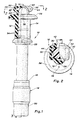
- an ignition cable terminal assembly for connecting an ignition cable to the terminal of a spark plug (not shown) located in a deep well or recess in an internal combustion engine (not shown) is indicated generally at 10.
- the ignition cable terminal assembly 10 comprises an elongated pipe 12 of hard plastic material, such as nylon or other suitable relatively rigid thermoplastic material, an elastomeric head cover 14 of hypalon or the like, an elastomeric seal sleeve 16 of silicone or other rubber-like material, and a pull bar 18 of hard plastic.
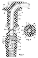
- the elongated pipe 12 houses an ignition terminal 20 which has a conventional corrugated crimp barrel 22 which attaches the ignition terminal 20 to an end of an ignition cable 24 in a conventional manner.
- the ignition terminal 20 is attached to the ignition cable 24 below the elongated pipe 12 and then "pulled to seat” against an internal shoulder 26 in the lower end of the elongated pipe 12 through the bottom opening of the elongated pipe.
- the ignition terminal 20 is pulled to seat by means of the ignition cable 24 which extends out of the top opening of the elongated pipe 12.
- the elongated pipe 12 has a curved wall 28 at its upper end which bends and redirects the ignition cable 24 from a vertical orientation in the elongated pipe 12 to a generally horizontal orientation at the top opening.
- the upper end of the curved wall 28 has a top plate 30 which provides a pair of laterally extending wings 32 for reinforcing a handle portion of the elastomeric head cover 14 as explained below.
- the upper portion of the elongated pipe 12 has an external flange 33 and two external ribs 34 which are used to locate and secure the elastomeric head cover 14 to the elongated pipe 12 as shown in Figure 3.
- the elastomeric head cover 14 has an annular seal flange 36 which seals the top of the engine well (not shown) in which the spark plug is seated when the ignition cable terminal assembly 10 is connected to the terminal of the spark plug.
- the annular seal flange 36 may also include a vent hole 38.
- the elastomeric head cover 14 also includes a handle portion 40 and a seal aperture 42 which are above the annular seal flange 36.
- the handle portion 40 is gripped by the user to connect or disconnect the ignition cable terminal assembly 10 to or from the terminal of the spark plug.
- the seal aperture 42 seals around the ignition cable 24 behind the top opening of the elongated pipe 12.
- the handle portion 40 of the elastomeric head cover 14 has two wing portions 44 which are spaced above the annular seal flange 36 as best seen in Figures 1 and 2. This shape permits the user to grip the handle portion 40 by inserting his index finger and his forefinger under the two respective wing portions 44 and pressing down on the top of the handle portion 40 with his thumb. Thus gripped, the ignition cable terminal assembly 10 is easily pushed down onto the spark plug or pulled off.
- the handle portion 40 of the elastomeric head cover 14 is reinforced by the top plate 30 of the hard plastic pipe 12 which has its laterally extending wings 32 embedded in the two wing portions 44 of the handle portion 40. Top plate 30 and laterally extending wings 32 thereby define reinforcement means. Consequently, the forces applied to the handle portion 40 by the user when connecting or disconnecting the ignition cable terminal assembly 10 are transferred from the handle portion 40 of the elastomeric head cover 14 immediately and directly to the top of the elongated pipe 12 via the top plate 30. Thus any stress which tends to stretch and tear the elastomeric head cover 14 is essentially avoided.
- the lower portion of the elongated pipe 12 has an external flange 45 and an external rib 46 which locate and retain the elastomeric seal sleeve 16 on the lower end of the elongated pipe 12.
- the elastomeric seal sleeve 16 has an internal groove 48 which accommodates external portions of the pull bar 18 and an internally ribbed end portion 50 which extends below the elongated tube 12 and sealingly engages the insulator of the spark plug (not shown) when the ignition cable terminal assembly 10 is connected to the spark plug.
- the pull bar 18 as best shown in Figures 3 and 4 has a head 52 which is disposed in the internal groove 48 of the elastomeric seal sleeve 16 and a shank 54 which extends transversely through a lower end portion of the elongated pipe 12 through holes 56 which are located below the internal shoulder 26.
- the shank 54 engages the lower end of the crimp barrel 22 of the ignition terminal 20 so the disengagement force is transferred from the elongated pipe 12 to the pull bar 18 to the ignition terminal 20 when the ignition cable terminal assembly 10 is pulled off the spark plug.
- the engagement force is transferred from the elongated pipe 12 directly to the ignition terminal 20 via the internal shoulder 26 when the ignition cable terminal assembly 10 is pushed onto the spark plug.
- the end of the shank 54 is bifurcated and provided with lock nibs 58 which retain the pull bar 18 in the absence of the elastomeric seal sleeve 16.
Landscapes
- Ignition Installations For Internal Combustion Engines (AREA)
- Spark Plugs (AREA)
Applications Claiming Priority (2)
| Application Number | Priority Date | Filing Date | Title |
|---|---|---|---|
| US322472 | 1989-03-13 | ||
| US07/322,472 US4906202A (en) | 1989-03-13 | 1989-03-13 | Deep well ignition cable terminal assembly |
Publications (2)
| Publication Number | Publication Date |
|---|---|
| EP0388024A1 true EP0388024A1 (fr) | 1990-09-19 |
| EP0388024B1 EP0388024B1 (fr) | 1993-07-21 |
Family
ID=23255062
Family Applications (1)
| Application Number | Title | Priority Date | Filing Date |
|---|---|---|---|
| EP90301743A Expired - Lifetime EP0388024B1 (fr) | 1989-03-13 | 1990-02-19 | Dispositif de connexion pour câble d'allumage |
Country Status (4)
| Country | Link |
|---|---|
| US (1) | US4906202A (fr) |
| EP (1) | EP0388024B1 (fr) |
| JP (1) | JP2509728B2 (fr) |
| DE (1) | DE69002261T2 (fr) |
Cited By (7)
| Publication number | Priority date | Publication date | Assignee | Title |
|---|---|---|---|---|
| EP0537566A3 (en) * | 1991-10-17 | 1993-09-22 | Kabelwerke Reinshagen Gmbh | Spark plug connector |
| DE4214816C1 (de) * | 1992-05-05 | 1993-10-21 | Daimler Benz Ag | Zündkerzenstecker für einen Verbrennungsmotor |
| EP0530883A3 (en) * | 1991-09-03 | 1993-11-18 | Gen Motors Corp | Spark plug connector and terminal assembly therefor |
| DE4314780A1 (de) * | 1992-10-02 | 1994-04-07 | Duerrwaechter E Dr Doduco | Zündkerzenstecker |
| EP0590657A3 (fr) * | 1992-10-02 | 1994-10-19 | Duerrwaechter E Dr Doduco | Connecteur de bougie d'allumage. |
| DE19515623A1 (de) * | 1995-04-28 | 1996-07-11 | Stihl Maschf Andreas | Zündkerzenstecker |
| EP1298579A1 (fr) * | 1992-09-28 | 2003-04-02 | Olympus Optical Co., Ltd. | Milieu d'enregistrement d'information,dispositif et méthode de reproduction des informations |
Families Citing this family (26)
| Publication number | Priority date | Publication date | Assignee | Title |
|---|---|---|---|---|
| US5033982A (en) * | 1990-05-31 | 1991-07-23 | Sun Microstamping, Inc. | Electrical connector |
| US5267869A (en) * | 1992-12-14 | 1993-12-07 | General Motors Corporation | Ignition cable assembly and method of making same |
| JPH06267639A (ja) * | 1993-03-12 | 1994-09-22 | Sumitomo Wiring Syst Ltd | 内燃機関用プラグキャップ装置 |
| US5547387A (en) * | 1993-08-05 | 1996-08-20 | Sumitomo Wiring Systems, Ltd. | Joint construction for ignition system |
| JPH0729792U (ja) * | 1993-11-01 | 1995-06-02 | 住友電装株式会社 | プラグキャップの空気抜き構造 |
| US5409388A (en) * | 1993-12-23 | 1995-04-25 | General Motors Corporation | Ignition cable assembly |
| JP2914195B2 (ja) * | 1994-10-14 | 1999-06-28 | 住友電装株式会社 | 内燃機関のプラグキャップ |
| JPH08124651A (ja) * | 1994-10-24 | 1996-05-17 | Sumitomo Wiring Syst Ltd | 点火ケーブル用プラグキャップ |
| JP3092783B2 (ja) * | 1995-05-12 | 2000-09-25 | 矢崎総業株式会社 | 点火プラグキャップ |
| US5799633A (en) * | 1997-08-08 | 1998-09-01 | Lexington Insulators | Electrical insulator with a duckbill-shaped valve |
| US6475002B2 (en) * | 1997-08-25 | 2002-11-05 | Robert Delsole | Spark plug wire boot securing system |
| US6302712B1 (en) * | 1997-08-25 | 2001-10-16 | Robert J. Delsole | Spark plug wire boot securing system |
| TWI355401B (en) * | 2006-09-29 | 2012-01-01 | Cheil Ind Inc | Thermoplastic resin composition and plastic articl |
| CN100447459C (zh) * | 2007-01-17 | 2008-12-31 | 渤海船舶重工有限责任公司 | 船舶艉轴温度传感器的密封装置及其安装方法 |
| KR101266294B1 (ko) * | 2008-12-19 | 2013-05-22 | 제일모직주식회사 | 폴리에스테르/폴리카보네이트 얼로이 수지 조성물 |
| KR101360892B1 (ko) | 2011-06-21 | 2014-02-11 | 제일모직주식회사 | 반사성, 내열성, 내황변성 및 내습성이 우수한 폴리에스테르 수지 조성물. |
| KR101549492B1 (ko) | 2011-12-28 | 2015-09-03 | 제일모직주식회사 | 내황변성과 내충격성이 우수한 폴리에스테르 수지 조성물 |
| KR20140086738A (ko) | 2012-12-28 | 2014-07-08 | 제일모직주식회사 | 수지 조성물 및 이를 포함한 성형품 |
| WO2014104485A1 (fr) | 2012-12-28 | 2014-07-03 | 제일모직 주식회사 | Composition de résine thermoplastique et article moulé comprenant celle-ci |
| US10301449B2 (en) | 2013-11-29 | 2019-05-28 | Lotte Advanced Materials Co., Ltd. | Thermoplastic resin composition having excellent light stability at high temperature |
| KR101577006B1 (ko) | 2013-12-09 | 2015-12-14 | 현대모비스 주식회사 | 열가소성 폴리카보네이트 수지조성물 |
| KR101690829B1 (ko) | 2013-12-30 | 2016-12-28 | 롯데첨단소재(주) | 내충격성 및 내광성이 우수한 열가소성 수지 조성물 |
| US10636951B2 (en) | 2014-06-27 | 2020-04-28 | Lotte Advanced Materials Co., Ltd. | Thermoplastic resin composition having excellent reflectivity |
| KR101793319B1 (ko) | 2014-12-17 | 2017-11-03 | 롯데첨단소재(주) | 폴리에스테르 수지 조성물 및 이로부터 제조된 성형품 |
| KR101849830B1 (ko) | 2015-06-30 | 2018-04-18 | 롯데첨단소재(주) | 내충격성 및 광신뢰성이 우수한 폴리에스테르 수지 조성물 및 이를 이용한 성형품 |
| DE102018108292B4 (de) * | 2017-11-17 | 2023-05-11 | Borgwarner Ludwigsburg Gmbh | Verbindungsstecker zum Anschließen einer Zündspule an eine Zündkerze sowie Schutzrohr für einen Verbindungsstecker |
Citations (3)
| Publication number | Priority date | Publication date | Assignee | Title |
|---|---|---|---|---|
| DE3619823A1 (de) * | 1985-06-12 | 1986-12-18 | Yazaki Corp., Tokio/Tokyo | Zuendkerzensteckverbindung |
| US4637358A (en) * | 1984-09-27 | 1987-01-20 | Honda Giken Kogyo Kabushiki Kaisha | Spark plug cap apparatus |
| US4790767A (en) * | 1987-11-16 | 1988-12-13 | Prestolite Wire Corporation | Electrical connector for a distributorless ignition system |
Family Cites Families (9)
| Publication number | Priority date | Publication date | Assignee | Title |
|---|---|---|---|---|
| DE2261103A1 (de) * | 1972-12-14 | 1974-06-20 | Kabel Metallwerke Ghh | Zuendkerzenstecker fuer verbrennungsmotoren |
| DE2730084C2 (de) * | 1977-07-02 | 1983-05-11 | kabelmetal electro GmbH, 3000 Hannover | Zündkerzenstecker in Winkelausführung |
| DE2809157A1 (de) * | 1978-03-03 | 1979-09-06 | Daimler Benz Ag | Zylinderkopf fuer eine gemischverdichtende brennkraftmaschine |
| US4390231A (en) * | 1978-06-28 | 1983-06-28 | General Motors Corporation | Blade terminal with protected latch tangs |
| US4319799A (en) * | 1980-04-11 | 1982-03-16 | General Motors Corporation | Electrical connector with group terminal lock |
| US4443047A (en) * | 1981-12-28 | 1984-04-17 | Brunswick Corporation | Spark plug wiring assembly |
| JPH0127581Y2 (fr) * | 1984-09-27 | 1989-08-18 | ||
| US4824385A (en) * | 1987-11-13 | 1989-04-25 | Prestolite Wire Corporation | Rigid sheath for a spark plug cable and its associated boot |
| US4810198A (en) * | 1987-11-13 | 1989-03-07 | Prestolite Wire Corporation | Reinforced boot for spark plug cables |
-
1989
- 1989-03-13 US US07/322,472 patent/US4906202A/en not_active Expired - Fee Related
-
1990
- 1990-02-19 EP EP90301743A patent/EP0388024B1/fr not_active Expired - Lifetime
- 1990-02-19 DE DE90301743T patent/DE69002261T2/de not_active Expired - Fee Related
- 1990-03-13 JP JP2060136A patent/JP2509728B2/ja not_active Expired - Lifetime
Patent Citations (3)
| Publication number | Priority date | Publication date | Assignee | Title |
|---|---|---|---|---|
| US4637358A (en) * | 1984-09-27 | 1987-01-20 | Honda Giken Kogyo Kabushiki Kaisha | Spark plug cap apparatus |
| DE3619823A1 (de) * | 1985-06-12 | 1986-12-18 | Yazaki Corp., Tokio/Tokyo | Zuendkerzensteckverbindung |
| US4790767A (en) * | 1987-11-16 | 1988-12-13 | Prestolite Wire Corporation | Electrical connector for a distributorless ignition system |
Cited By (9)
| Publication number | Priority date | Publication date | Assignee | Title |
|---|---|---|---|---|
| EP0530883A3 (en) * | 1991-09-03 | 1993-11-18 | Gen Motors Corp | Spark plug connector and terminal assembly therefor |
| EP0537566A3 (en) * | 1991-10-17 | 1993-09-22 | Kabelwerke Reinshagen Gmbh | Spark plug connector |
| DE4214816C1 (de) * | 1992-05-05 | 1993-10-21 | Daimler Benz Ag | Zündkerzenstecker für einen Verbrennungsmotor |
| FR2691018A1 (fr) * | 1992-05-05 | 1993-11-12 | Daimler Benz Ag | Agencement d'une cosse de bougie d'allumage pour moteurs à combustion interne. |
| EP1298579A1 (fr) * | 1992-09-28 | 2003-04-02 | Olympus Optical Co., Ltd. | Milieu d'enregistrement d'information,dispositif et méthode de reproduction des informations |
| US6622276B2 (en) | 1992-09-28 | 2003-09-16 | Olympus Optical Co., Ltd. | Recording medium, information reproducing apparatus and information reproducing method |
| DE4314780A1 (de) * | 1992-10-02 | 1994-04-07 | Duerrwaechter E Dr Doduco | Zündkerzenstecker |
| EP0590657A3 (fr) * | 1992-10-02 | 1994-10-19 | Duerrwaechter E Dr Doduco | Connecteur de bougie d'allumage. |
| DE19515623A1 (de) * | 1995-04-28 | 1996-07-11 | Stihl Maschf Andreas | Zündkerzenstecker |
Also Published As
| Publication number | Publication date |
|---|---|
| DE69002261D1 (de) | 1993-08-26 |
| EP0388024B1 (fr) | 1993-07-21 |
| DE69002261T2 (de) | 1993-11-04 |
| JP2509728B2 (ja) | 1996-06-26 |
| US4906202A (en) | 1990-03-06 |
| JPH02283862A (ja) | 1990-11-21 |
Similar Documents
| Publication | Publication Date | Title |
|---|---|---|
| EP0388024B1 (fr) | Dispositif de connexion pour câble d'allumage | |
| EP0501745B1 (fr) | Connecteur à vissage à double dureté | |
| CA2251520C (fr) | Assemblage de verification du raccordement realise au moyen d'un raccord de tuyau | |
| US4629351A (en) | Fitting indicating mechanism in screw type connector housings | |
| EP1547645A3 (fr) | Dispositif de connexion de tube médical | |
| US5872335A (en) | 90 degree sealing nut | |
| US4780942A (en) | Fuel injector puller | |
| EP0800236A3 (fr) | Construction de connexion pour éléments tubulaires | |
| EP1413816B1 (fr) | Raccords de tuyaux comprenant dispositifs de fermeture provisoire | |
| CA2119834A1 (fr) | Raccord metallique pour isolateur composite | |
| EP0739779A3 (fr) | Structure de connexion d'un réseau de cables d'un levier de vitesse | |
| EP0187952B1 (fr) | Goupille avec un manteau de sécurité métallique | |
| EP0637856B1 (fr) | Construction d'un connecteur pour un système d'allumage | |
| US6193543B1 (en) | Adjustable retainer for electrical cords | |
| US4947809A (en) | Ignition boot | |
| EP1215769A2 (fr) | Connecteur étanche | |
| EP0530883A2 (fr) | Connecteur de bougie d'allumage et son ensemble de borne | |
| RU96112108A (ru) | Корпус для кабеля | |
| EP0733889A3 (fr) | Equipement pour attacher un palpeur de pression à un substrat | |
| US4758189A (en) | Damage resistant spark plug terminal connector | |
| JP3285298B2 (ja) | 防水コネクタの防水栓引き抜き方法及び該方法に使用する防水栓並びに治具 | |
| JP4168266B2 (ja) | 閉鎖キャップ | |
| CN210778291U (zh) | 一种防水按钮开关 | |
| US6981310B2 (en) | Handgrip installation tool | |
| JPH11144839A (ja) | プラグキャップ着脱用ホルダ |
Legal Events
| Date | Code | Title | Description |
|---|---|---|---|
| PUAI | Public reference made under article 153(3) epc to a published international application that has entered the european phase |
Free format text: ORIGINAL CODE: 0009012 |
|
| AK | Designated contracting states |
Kind code of ref document: A1 Designated state(s): DE FR GB IT |
|
| 17P | Request for examination filed |
Effective date: 19900917 |
|
| 17Q | First examination report despatched |
Effective date: 19921119 |
|
| ITF | It: translation for a ep patent filed | ||
| GRAA | (expected) grant |
Free format text: ORIGINAL CODE: 0009210 |
|
| AK | Designated contracting states |
Kind code of ref document: B1 Designated state(s): DE FR GB IT |
|
| REF | Corresponds to: |
Ref document number: 69002261 Country of ref document: DE Date of ref document: 19930826 |
|
| ET | Fr: translation filed | ||
| PLBE | No opposition filed within time limit |
Free format text: ORIGINAL CODE: 0009261 |
|
| STAA | Information on the status of an ep patent application or granted ep patent |
Free format text: STATUS: NO OPPOSITION FILED WITHIN TIME LIMIT |
|
| 26N | No opposition filed | ||
| ITTA | It: last paid annual fee | ||
| PGFP | Annual fee paid to national office [announced via postgrant information from national office to epo] |
Ref country code: GB Payment date: 19970127 Year of fee payment: 8 |
|
| PGFP | Annual fee paid to national office [announced via postgrant information from national office to epo] |
Ref country code: FR Payment date: 19970227 Year of fee payment: 8 |
|
| PGFP | Annual fee paid to national office [announced via postgrant information from national office to epo] |
Ref country code: DE Payment date: 19970411 Year of fee payment: 8 |
|
| PG25 | Lapsed in a contracting state [announced via postgrant information from national office to epo] |
Ref country code: GB Free format text: LAPSE BECAUSE OF NON-PAYMENT OF DUE FEES Effective date: 19980219 |
|
| PG25 | Lapsed in a contracting state [announced via postgrant information from national office to epo] |
Ref country code: FR Free format text: THE PATENT HAS BEEN ANNULLED BY A DECISION OF A NATIONAL AUTHORITY Effective date: 19980228 |
|
| GBPC | Gb: european patent ceased through non-payment of renewal fee |
Effective date: 19980219 |
|
| PG25 | Lapsed in a contracting state [announced via postgrant information from national office to epo] |
Ref country code: DE Free format text: LAPSE BECAUSE OF NON-PAYMENT OF DUE FEES Effective date: 19981103 |
|
| REG | Reference to a national code |
Ref country code: FR Ref legal event code: ST |
|
| PG25 | Lapsed in a contracting state [announced via postgrant information from national office to epo] |
Ref country code: IT Free format text: LAPSE BECAUSE OF NON-PAYMENT OF DUE FEES;WARNING: LAPSES OF ITALIAN PATENTS WITH EFFECTIVE DATE BEFORE 2007 MAY HAVE OCCURRED AT ANY TIME BEFORE 2007. THE CORRECT EFFECTIVE DATE MAY BE DIFFERENT FROM THE ONE RECORDED. Effective date: 20050219 |