EP0388099A2 - Überwachung einer Batterie - Google Patents
Überwachung einer Batterie Download PDFInfo
- Publication number
- EP0388099A2 EP0388099A2 EP90302565A EP90302565A EP0388099A2 EP 0388099 A2 EP0388099 A2 EP 0388099A2 EP 90302565 A EP90302565 A EP 90302565A EP 90302565 A EP90302565 A EP 90302565A EP 0388099 A2 EP0388099 A2 EP 0388099A2
- Authority
- EP
- European Patent Office
- Prior art keywords
- battery
- frequency
- eddy currents
- charge
- current
- Prior art date
- Legal status (The legal status is an assumption and is not a legal conclusion. Google has not performed a legal analysis and makes no representation as to the accuracy of the status listed.)
- Granted
Links
Images

Classifications
-
- G—PHYSICS
- G01—MEASURING; TESTING
- G01R—MEASURING ELECTRIC VARIABLES; MEASURING MAGNETIC VARIABLES
- G01R31/00—Arrangements for testing electric properties; Arrangements for locating electric faults; Arrangements for electrical testing characterised by what is being tested not provided for elsewhere
- G01R31/36—Arrangements for testing, measuring or monitoring the electrical condition of accumulators or electric batteries, e.g. capacity or state of charge [SoC]
-
- H—ELECTRICITY
- H02—GENERATION; CONVERSION OR DISTRIBUTION OF ELECTRIC POWER
- H02J—ELECTRIC POWER NETWORKS; CIRCUIT ARRANGEMENTS OR SYSTEMS FOR SUPPLYING OR DISTRIBUTING ELECTRIC POWER; SYSTEMS FOR STORING ELECTRIC ENERGY
- H02J7/00—Circuit arrangements for charging or discharging batteries or for supplying loads from batteries
- H02J7/90—Regulation of charging or discharging current or voltage
- H02J7/933—Regulation of charging or discharging current or voltage the cycle being controlled or terminated in response to electric parameters
Definitions
- This invention relates to monitoring state of charge condition of an electric storage battery, and has application to current supply management systems using batteries at least as alternative sources of electric power.
- state of charge conditions for lead acid type batteries has been determined or monitored by measurement of electrolyte specific gravity or battery voltage.
- such techniques are unsatisfactory for sealed lead acid batteries partly because electrolyte cannot be extracted for analysis without damaging the battery and partly because battery voltage is not directly proportional to state of charge.
- the most common method used for charging of lead acid batteries on a continuous basis is to supply to the battery terminals a fixed voltage of a value which will just allow sufficient current to flow into the fully charged battery to replace energy lost by spontaneous self-discharge of the battery active materials.
- this can lead to excessive heat generation at least when the ambient temperature is high enough to initiate a fast rate of oxygen production inside the battery at the selected charging voltage. That can result in damage to the battery case, loss of water from the battery and corrosion of grid material.
- battery state of charge condition is monitored according to eddy currents deliberately induced in negative plate material of the battery concerned, conveniently using an externally applied varying magnetic field of suitable effective frequency, typically from an induction coil placed close to the outside of the battery case, though a specific housing compartment or attachment provision could be made in designing the battery case.
- this invention is applicable to any battery having material capable of supporting eddy-currents in a manner dependent on the state of charge of the battery.
- nickel-cadmium type batteries which generally have flatter voltage/charge-state characteristics during discharge (than lead-acid batteries), are equally suitable for charge state monitoring using embodiments of this invention.
- An initial value corresponding to full charge state of the battery can be obtained by measuring maximum amplitude for high frequency current signal produced while the battery is on floating charge.
- frequency effects are also capable of utilisation to detect eddy current effects, or a combination of amplitude and frequency effects.
- an inductive device embodying this invention or forming part of such embodiment and placed in eddy-current inducing relation with the battery being charged is useful and advantageous.
- an inductive device embodying this invention or forming part of such embodiment is placed to induce eddy currents in at least a selected cell of the storage battery concerned. Then, such inductive device can continuously monitor the state of charge of the battery generally, and/or the rate of change of the state of charge of the storage battery while the battery is being discharged. This information can be processed to calculate an expected time for which the current (or any particular power) output can be maintained by the system before mains is available again.
- an inductive device embodying this invention or forming part of such embodiment can detect a condition where oxygen gas is produced by the battery positive plates.
- the oxygen gas generated while charging the battery reacts with negative plate active material leading to a reduction in the eddy current induced and measured using the inductive device.
- the value of the induced eddy currents in the negative plate active material decreases while the battery is on charge and use can be made of means, conveniently including a switch, operative when required to limit charge current to a level that is unable to generate sufficient heat to damage the battery.
- Such provisions applied to or incorporated into a charging system for a motor vehicle battery, typically to supply power for starting, lighting, ignition and ancilliary electrical equipment of the vehicle, can allow a single design of charging system to be used without adjustment across the widest range of possible climatic and other operating conditions, the limited charge current level simply being switched in for periods and at intervals assuring that battery charging is effective and not liable to cause damage.
- line (a) represents variation of battery voltage (left ordinate) with state of charge of a battery (abscissa). That variation is clearly non-linear.
- Line (b) represents variation (with state of charge) of eddy-current dependent monitoring voltage (right ordinate) obtained by practising this invention. That variation is substantially linear.
- the lines (a) and (b) of Figure 1 are idealised from test data obtained relative to a Yuasa Model NP7-12 battery, which is of sealed lead-acid type, using as an inductive device a Honeywell Model 924 inductive promixity sensor placed next to the battery case. Measured working frequency ranged from 75 KHz to 135 KHz and resulting current/voltage variation as shown in Figure 1.
- Figure 2 shows bands of recommended charging voltages for similar Yuasa 12 volt and 6 volt oxygen recombination batteries (leftmost and middle left ordinates) and on a per-battery-cell basis (rightmost left ordinate) over a range of ambient temperatures from -10°C (14°F) to above 50°C (120°F).
- One of the illustrated bands (upper) relates to batteries on continuous or cyclic use and the other illustrated band (lower) relates to batteries on stand-by use only.
- there is no single charging voltage that can be selected to serve for the whole range of operating conditions, even simply on a temperature basis for a particular model (size) of battery.
- slopes of the upper band shown in Figure 2 can be different for different battery designs, and even for individual batteries of the same type, both of which further militate against ready application of charging current control according to temperature, particularly in a general way compatible with mass-production of motor vehicles.
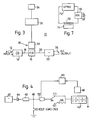
- Figure 3 shows application of an embodiment of this invention to an uninterruptable electrical power supply (10) for such as electronic equipment, typically a computer installation, requiring permanent power on a stand-by or emergency basis in the event of failure of electric mains.
- Mains input is indicated at 12 going via a rectifier 14, thence over line 16 to a battery 18 for continuous charging purposes.
- Battery output 20 supplies an inverter 22 for alternating current output at 24. It will be appreciated that Figure 3 shows only emergency supply provisions, and that some installations may not require inversion to provide a-c power.
- an inductive device 30 Shown at 26 adjacent to the battery 18 is an inductive device 30, whose purpose is to induce and detect changes of eddy current effects in negative plate active material of the battery 18.
- a typical inductive device 30 will comprise an induction coil to generate a magnetic field in negative plate(s) of the battery 18, at least in part(s) or to extent(s) sufficient for inducing eddy currents with effects useful herein when energised at a suitable frequency or frequencies.
- Resulting eddy currents induced in negative plate active material of the battery cause reduction in current in the induction coil that is related to the charge state of the battery, increasing as the battery charges and decreasing as the battery discharges, see line b of Figure 1.
- the inductive device 30 is shown associated with signal processing means 32 and related display means 34.
- the processing means 32 will usually include calculating means for state of charge to the battery and for time for the battery to reach zero charge, or a charge below which electric and/or electronic equipment cannot be supplied safely. Then, operators will be able to judge how long the full installation can be run before at least partial close-down for a computer installation, say of electric drives first, then of active data processing.
- FIG. 4 shows application to a motor vehicle battery 40 for starting, lighting, ignition and auxiliary equipment.
- Output from an a-c generator 42 goes by way of a rectifier 44 and voltage regulator 46 to a node 48 from which the vehicle load 50 is supplied.
- a charge/discharge detector 52 with an associated switch 54 for controlling whether or not the battery 40 receives reduced charging current from the node 48 over charge current limiting device 56, or a higher level of charging current in the switch state shown.
- An inductive device hereof for detecting charge state of the battery is shown at 58 in proximity to the battery 40 and associated with a charge state controller 60 also connected to the charge/discharge detector 52.
- a valve regulated or oxygen recombination lead acid battery has several advantages, including being substantially maintenance-free, compared with conventional flooded lead acid batteries for motor vehicle applications. Those advantages further include reduced weight and size, absence of spillable acid, safe operation in any orientation, and, of course, no requirement for water addition during operating life.
- the preferred charging method for lead acid batteries is to use an electrical D.C. supply of fixed voltage and variable current output.
- the charger voltage can be set so that when the battery is fully charged the charging current falls to a normal low level sufficient only to replace energy losses in the battery active materials.
- an electrolytic reaction is promoted at the battery positive plates which generates oxygen gas.
- the oxygen gas diffuses to the battery negative plate where it combines with the spongy lead active material in an exothermic reaction.
- the oxidised lead is subsequently converted back to spongy lead to complete a cyclic process which results in the conversion of electrical energy into heat within the charged battery.
- the battery charging system serves to limit the rate of oxygen production in charging the battery 40.
- the AC generator 42 produces a current which is rectified 44 and supplied at a voltage determined by the regulator 46.
- the direction of current into or out of the battery is detected by the detector 52, conveniently an ammeter.
- the state of charge of the battery is monitored by the inductive device 58 which induces high frequency eddy currents in the active material of the battery negative plates, and switching to a yet lower level of charging current is provided for.
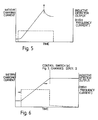
- amplitude of the high frequency current increases as the volume of active material increases during charging up to a maximum (x).
- oxygen generation begins at the positive battery plates.
- the oxygen reacts with the surfaces of the negative active material particles resulting in a reduction of the amplitude of the eddy currents induced by the inductive device 58, typically an electromagnetic coil.
- the charging controller 60 detects both that a charging current is flowing and that the amplitude of eddy currents in the negative active material is decreasing it causes the switch 54 to change from the illustrated state (1), which is direct connection of charger to battery, to its other state (2) which includes a current limiting device 56.
- the control switch 56 resets to state (1) when the vehicle ignition is switched off or net discharging current is detected at ammeter 52.
- Frequency of operation could be left as a matter of achieving resonance for an inductive coil including its coupling to the battery, typically metal electrode material. Then changing frequency to follow resonance according to battery state of charge can be converted into correspondingly changing voltage.
- Circuitry for a conventional inductive proximity sensor is suitable or readily adapted to the purposes hereof, and is shown in highly simplified form in Figure 7.
- inductance coil 70 is driven by variable frequency oscillator 72 in a resonance achieving manner according to coupling with battery material 74, and a frequency to voltage converter 76 gives requisite charge state sensing voltage VS at output 78.
- the inductance coil 70 is conveniently located touching the battery case and axially aligned with one negative plate.
- Apparatus for practising this invention could be a simple probe pack capable of being brought into suitable proximity to a battery, or a pack that can be attached to a battery casing.
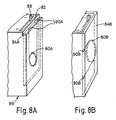
- another approach is to form the battery casing with a pocket to house an inductive probe or probe pack, see Figure 8A at 80A for the inductive coil probe end 82 for the pocket on an end wall 84A of the battery casing 86 next to negative electrode terminal 88 and with flying leads 90A for connection of the probe 80A to excitation/detection circuitry.
- Figure 8B shows inductive coil probe 80B is shown embedded in the thickness of end wall 84B and has connection studs 90B at the edge of that wall.
Landscapes
- Engineering & Computer Science (AREA)
- Power Engineering (AREA)
- Physics & Mathematics (AREA)
- General Physics & Mathematics (AREA)
- Secondary Cells (AREA)
- Charge And Discharge Circuits For Batteries Or The Like (AREA)
- Cell Electrode Carriers And Collectors (AREA)
- Primary Cells (AREA)
- Electric Propulsion And Braking For Vehicles (AREA)
Priority Applications (1)
| Application Number | Priority Date | Filing Date | Title |
|---|---|---|---|
| AT90302565T ATE99807T1 (de) | 1989-03-13 | 1990-03-09 | Ueberwachung einer batterie. |
Applications Claiming Priority (2)
| Application Number | Priority Date | Filing Date | Title |
|---|---|---|---|
| GB8905708 | 1989-03-13 | ||
| GB898905708A GB8905708D0 (en) | 1989-03-13 | 1989-03-13 | Battery monitoring |
Publications (3)
| Publication Number | Publication Date |
|---|---|
| EP0388099A2 true EP0388099A2 (de) | 1990-09-19 |
| EP0388099A3 EP0388099A3 (de) | 1991-08-21 |
| EP0388099B1 EP0388099B1 (de) | 1994-01-05 |
Family
ID=10653223
Family Applications (1)
| Application Number | Title | Priority Date | Filing Date |
|---|---|---|---|
| EP90302565A Expired - Lifetime EP0388099B1 (de) | 1989-03-13 | 1990-03-09 | Überwachung einer Batterie |
Country Status (5)
| Country | Link |
|---|---|
| US (1) | US5093624A (de) |
| EP (1) | EP0388099B1 (de) |
| AT (1) | ATE99807T1 (de) |
| DE (1) | DE69005672T2 (de) |
| GB (1) | GB8905708D0 (de) |
Cited By (5)
| Publication number | Priority date | Publication date | Assignee | Title |
|---|---|---|---|---|
| EP0568767A1 (de) * | 1992-05-08 | 1993-11-10 | VARTA Batterie Aktiengesellschaft | Verfahren zur Bestimmung des Ladezustandes einer elektrochemischen Zelle |
| FR2737923A1 (fr) * | 1995-08-16 | 1997-02-21 | Centre Nat Etd Spatiales | Dispositif et procede de mesure externe, sans contact electrique, de l'etat de charge d'un accumulateur electrique |
| EP2607911A1 (de) * | 2011-12-23 | 2013-06-26 | Saft | Bestimmungsmethode eines Zustandsparameters eines elektrochemischen Elements mit Hilfe der komplexen Impedanz der Funkfrequenzen |
| WO2016042488A1 (en) * | 2014-09-16 | 2016-03-24 | Wayne State University | Battery state of charge estimator |
| CN110867922A (zh) * | 2019-11-27 | 2020-03-06 | 威海安屯尼智能电子科技有限公司 | 一种浮充阶段拉高电压的脉冲充电方法及电源充电器 |
Families Citing this family (19)
| Publication number | Priority date | Publication date | Assignee | Title |
|---|---|---|---|---|
| US5250903A (en) * | 1989-05-31 | 1993-10-05 | Amoco Corporation | Method and apparatus using oscillatory magnetic field to determine state of charge of an electrolytic storage cell |
| US5650937A (en) * | 1991-11-08 | 1997-07-22 | Universite Paris Val De Marne | Device and method for measuring the charge state of a nickel-cadmium accumulator |
| US5537042A (en) * | 1994-11-18 | 1996-07-16 | Eldec Corporation | Method and system for unobtrusively measuring physical properties in electrochemical processes |
| US5777454A (en) * | 1996-05-29 | 1998-07-07 | Peco Ii, Inc. | Back-up battery management system for a DC power supply |
| US5886503A (en) * | 1996-05-29 | 1999-03-23 | Peco Ii, Inc. | Back-up battery management apparatus for charging and testing individual battery cells in a string of battery cells |
| US7783438B2 (en) * | 2006-10-31 | 2010-08-24 | Enerize Corporation | Integrated non-destructive method and device for electrochemical energy system diagnostics |
| US7928690B2 (en) * | 2007-11-29 | 2011-04-19 | GM Global Technology Operations LLC | Method and system for determining a state of charge of a battery |
| US9851408B2 (en) * | 2008-06-05 | 2017-12-26 | Cadex Electronics Inc. | Methods and apparatus for battery testing |
| CA2749334A1 (en) * | 2008-06-05 | 2009-12-10 | Cadex Electronics Inc. | Methods and apparatus for battery testing |
| US8872519B2 (en) * | 2008-09-26 | 2014-10-28 | GM Global Technology Operations LLC | System and method to determine the state of charge of a battery using magnetostriction to detect magnetic response of battery material |
| DE102009042618B4 (de) | 2008-09-26 | 2022-02-10 | GM Global Technology Operations LLC (n. d. Ges. d. Staates Delaware) | System und Verfahren zum Bestimmen des Ladezustands einer Batterie unter Verwendung von Magnetostriktion, um eine magnetische Reaktion von Batteriematerial zu detektieren |
| US9086460B2 (en) | 2009-02-05 | 2015-07-21 | Methode Electronics, Inc. | Apparatus and method for monitoring the state of charge of a battery cell |
| US9511670B2 (en) * | 2011-12-07 | 2016-12-06 | GM Global Technology Operations LLC | Magnetic sensor transformer for determining state of charge for iron phosphate lithium ion batteries |
| FR2985613A1 (fr) * | 2012-01-09 | 2013-07-12 | Commissariat Energie Atomique | Detection d'un dysfonctionnement dans un accumulateur electrochimique |
| DE102014202617B4 (de) * | 2014-02-13 | 2025-06-12 | Robert Bosch Gmbh | Verfahren und Vorrichtung zum Messen eines Batteriezellenstromes |
| JP6864536B2 (ja) * | 2017-04-25 | 2021-04-28 | 株式会社東芝 | 二次電池システム、充電方法、プログラム、及び車両 |
| CN107394848A (zh) * | 2017-08-25 | 2017-11-24 | 湖北尚纬新能源技术有限公司 | 基于非接触式储能电池监测的控制装置 |
| US12571851B2 (en) | 2020-03-25 | 2026-03-10 | Cadex Electronics Inc. | Apparatus and methods for testing electrochemical systems |
| US12184106B2 (en) * | 2020-07-21 | 2024-12-31 | Purdue Research Foundation | System and methods for rechargeable battery diagnostics |
Family Cites Families (3)
| Publication number | Priority date | Publication date | Assignee | Title |
|---|---|---|---|---|
| US3787754A (en) * | 1972-08-16 | 1974-01-22 | Us Army | Apparatus for controlling charging of storage batteries with sensing the d.c. of the electrolyte |
| US4260230A (en) * | 1978-04-18 | 1981-04-07 | Canon Kabushiki Kaisha | Charge device for secondary batteries |
| FR2542873B1 (fr) * | 1983-03-16 | 1985-06-14 | Asulab Sa | Procede de mesure de l'etat de decharge d'une pile et appareil mettant en oeuvre ce procede |
-
1989
- 1989-03-13 GB GB898905708A patent/GB8905708D0/en active Pending
-
1990
- 1990-03-09 AT AT90302565T patent/ATE99807T1/de not_active IP Right Cessation
- 1990-03-09 EP EP90302565A patent/EP0388099B1/de not_active Expired - Lifetime
- 1990-03-09 DE DE69005672T patent/DE69005672T2/de not_active Expired - Fee Related
- 1990-03-13 US US07/492,721 patent/US5093624A/en not_active Expired - Lifetime
Cited By (6)
| Publication number | Priority date | Publication date | Assignee | Title |
|---|---|---|---|---|
| EP0568767A1 (de) * | 1992-05-08 | 1993-11-10 | VARTA Batterie Aktiengesellschaft | Verfahren zur Bestimmung des Ladezustandes einer elektrochemischen Zelle |
| FR2737923A1 (fr) * | 1995-08-16 | 1997-02-21 | Centre Nat Etd Spatiales | Dispositif et procede de mesure externe, sans contact electrique, de l'etat de charge d'un accumulateur electrique |
| EP2607911A1 (de) * | 2011-12-23 | 2013-06-26 | Saft | Bestimmungsmethode eines Zustandsparameters eines elektrochemischen Elements mit Hilfe der komplexen Impedanz der Funkfrequenzen |
| US9453884B2 (en) | 2011-12-23 | 2016-09-27 | Saft | Method for determining a state variable of an electrochemical cell using complex impedance at radioelectric frequencies |
| WO2016042488A1 (en) * | 2014-09-16 | 2016-03-24 | Wayne State University | Battery state of charge estimator |
| CN110867922A (zh) * | 2019-11-27 | 2020-03-06 | 威海安屯尼智能电子科技有限公司 | 一种浮充阶段拉高电压的脉冲充电方法及电源充电器 |
Also Published As
| Publication number | Publication date |
|---|---|
| GB8905708D0 (en) | 1989-04-26 |
| EP0388099A3 (de) | 1991-08-21 |
| ATE99807T1 (de) | 1994-01-15 |
| DE69005672T2 (de) | 1994-06-01 |
| DE69005672D1 (de) | 1994-02-17 |
| US5093624A (en) | 1992-03-03 |
| EP0388099B1 (de) | 1994-01-05 |
Similar Documents
| Publication | Publication Date | Title |
|---|---|---|
| EP0388099B1 (de) | Überwachung einer Batterie | |
| US5557189A (en) | Method and apparatus including a current detector and a power source control circuit for charging a number of batteries | |
| US5861730A (en) | Battery charging apparatus | |
| US5245269A (en) | Battery temperature sensing apparatus | |
| FI96370B (sv) | Förfarande för att kontrollera den interna impedansen hos ett ackumulatorbatteri i en reservströmkälla och en reservströmkälla | |
| CA2042100C (en) | Battery charging system | |
| US4086525A (en) | Circuit for preventing overdischarge of a battery | |
| JP3747071B2 (ja) | 電源システム | |
| JPH06217463A (ja) | 電池を電源とする電子装置用の電力管理装置および電池パックにおいて利用可能な電力量を決定する方法 | |
| EP0631363B1 (de) | Ladeschaltung mit einer Schaltung zur Überwachung des Ladezustandes einer Batterie | |
| CN112771708A (zh) | 蓄电元件的劣化度以及蓄电余量检测装置和蓄电元件管理单元 | |
| KR20080095642A (ko) | 부하변조 기능을 갖는 무접점 충전 배터리 및 이를 구비한배터리 충전 세트 | |
| US7129676B2 (en) | Controlling re-charge of a nickel metal-hydride (NiMH) or nickel cadmuim (NiCd) battery | |
| EP0126936A3 (de) | Batterielader mit Hochfrequenzkommutierung | |
| KR101734724B1 (ko) | 전기 자동차의 누전 검출 장치 | |
| FR2670953B1 (fr) | Procede et dispositif pour charger un accumulateur. | |
| KR100903461B1 (ko) | 무 접점 충전기 및 이를 구비한 배터리 충전 세트 | |
| JP3945563B2 (ja) | 二次電池装置 | |
| GB2271228A (en) | Controlling charging of a battery in an uninterruptible power supply | |
| JP3346821B2 (ja) | 充電装置 | |
| KR950009337B1 (ko) | 배터리 충전회로 | |
| JP3219498B2 (ja) | 2次電池の充電回路 | |
| JPS58107030A (ja) | ソ−ラ−・ジエネレ−タ−の出力を検知する装置 | |
| JPS6094160A (ja) | 電気集塵装置の運転方法 | |
| JPS5829337A (ja) | 直流電源装置 |
Legal Events
| Date | Code | Title | Description |
|---|---|---|---|
| PUAI | Public reference made under article 153(3) epc to a published international application that has entered the european phase |
Free format text: ORIGINAL CODE: 0009012 |
|
| AK | Designated contracting states |
Kind code of ref document: A2 Designated state(s): AT BE CH DE DK ES FR GB GR IT LI LU NL SE |
|
| PUAL | Search report despatched |
Free format text: ORIGINAL CODE: 0009013 |
|
| AK | Designated contracting states |
Kind code of ref document: A3 Designated state(s): AT BE CH DE DK ES FR GB GR IT LI LU NL SE |
|
| RHK1 | Main classification (correction) |
Ipc: G01R 31/36 |
|
| 17P | Request for examination filed |
Effective date: 19911021 |
|
| 17Q | First examination report despatched |
Effective date: 19930310 |
|
| GRAA | (expected) grant |
Free format text: ORIGINAL CODE: 0009210 |
|
| AK | Designated contracting states |
Kind code of ref document: B1 Designated state(s): AT BE CH DE DK ES FR GB GR IT LI LU NL SE |
|
| PG25 | Lapsed in a contracting state [announced via postgrant information from national office to epo] |
Ref country code: IT Free format text: LAPSE BECAUSE OF FAILURE TO SUBMIT A TRANSLATION OF THE DESCRIPTION OR TO PAY THE FEE WITHIN THE PRESCRIBED TIME-LIMIT;WARNING: LAPSES OF ITALIAN PATENTS WITH EFFECTIVE DATE BEFORE 2007 MAY HAVE OCCURRED AT ANY TIME BEFORE 2007. THE CORRECT EFFECTIVE DATE MAY BE DIFFERENT FROM THE ONE RECORDED. Effective date: 19940105 Ref country code: DK Effective date: 19940105 Ref country code: SE Effective date: 19940105 Ref country code: ES Free format text: THE PATENT HAS BEEN ANNULLED BY A DECISION OF A NATIONAL AUTHORITY Effective date: 19940105 Ref country code: AT Effective date: 19940105 Ref country code: GR Free format text: LAPSE BECAUSE OF FAILURE TO SUBMIT A TRANSLATION OF THE DESCRIPTION OR TO PAY THE FEE WITHIN THE PRESCRIBED TIME-LIMIT Effective date: 19940105 |
|
| REF | Corresponds to: |
Ref document number: 99807 Country of ref document: AT Date of ref document: 19940115 Kind code of ref document: T |
|
| REF | Corresponds to: |
Ref document number: 69005672 Country of ref document: DE Date of ref document: 19940217 |
|
| PG25 | Lapsed in a contracting state [announced via postgrant information from national office to epo] |
Ref country code: LU Free format text: LAPSE BECAUSE OF NON-PAYMENT OF DUE FEES Effective date: 19940331 |
|
| ET | Fr: translation filed | ||
| PLBE | No opposition filed within time limit |
Free format text: ORIGINAL CODE: 0009261 |
|
| STAA | Information on the status of an ep patent application or granted ep patent |
Free format text: STATUS: NO OPPOSITION FILED WITHIN TIME LIMIT |
|
| 26N | No opposition filed | ||
| PGFP | Annual fee paid to national office [announced via postgrant information from national office to epo] |
Ref country code: CH Payment date: 19980318 Year of fee payment: 9 |
|
| PGFP | Annual fee paid to national office [announced via postgrant information from national office to epo] |
Ref country code: NL Payment date: 19980320 Year of fee payment: 9 |
|
| PGFP | Annual fee paid to national office [announced via postgrant information from national office to epo] |
Ref country code: BE Payment date: 19980415 Year of fee payment: 9 |
|
| PG25 | Lapsed in a contracting state [announced via postgrant information from national office to epo] |
Ref country code: CH Free format text: LAPSE BECAUSE OF NON-PAYMENT OF DUE FEES Effective date: 19990331 Ref country code: LI Free format text: LAPSE BECAUSE OF NON-PAYMENT OF DUE FEES Effective date: 19990331 Ref country code: BE Free format text: LAPSE BECAUSE OF NON-PAYMENT OF DUE FEES Effective date: 19990331 |
|
| BERE | Be: lapsed |
Owner name: YUASA BATTERY (UK) LTD Effective date: 19990331 |
|
| PG25 | Lapsed in a contracting state [announced via postgrant information from national office to epo] |
Ref country code: NL Free format text: LAPSE BECAUSE OF NON-PAYMENT OF DUE FEES Effective date: 19991001 |
|
| REG | Reference to a national code |
Ref country code: CH Ref legal event code: PL |
|
| NLV4 | Nl: lapsed or anulled due to non-payment of the annual fee |
Effective date: 19991001 |
|
| REG | Reference to a national code |
Ref country code: GB Ref legal event code: IF02 |
|
| PGFP | Annual fee paid to national office [announced via postgrant information from national office to epo] |
Ref country code: DE Payment date: 20020527 Year of fee payment: 13 |
|
| PG25 | Lapsed in a contracting state [announced via postgrant information from national office to epo] |
Ref country code: DE Free format text: LAPSE BECAUSE OF NON-PAYMENT OF DUE FEES Effective date: 20031001 |
|
| PGFP | Annual fee paid to national office [announced via postgrant information from national office to epo] |
Ref country code: GB Payment date: 20050413 Year of fee payment: 16 |
|
| PGFP | Annual fee paid to national office [announced via postgrant information from national office to epo] |
Ref country code: FR Payment date: 20050421 Year of fee payment: 16 |
|
| PG25 | Lapsed in a contracting state [announced via postgrant information from national office to epo] |
Ref country code: GB Free format text: LAPSE BECAUSE OF NON-PAYMENT OF DUE FEES Effective date: 20060309 |
|
| GBPC | Gb: european patent ceased through non-payment of renewal fee |
Effective date: 20060309 |
|
| REG | Reference to a national code |
Ref country code: FR Ref legal event code: ST Effective date: 20061130 |
|
| PG25 | Lapsed in a contracting state [announced via postgrant information from national office to epo] |
Ref country code: FR Free format text: LAPSE BECAUSE OF NON-PAYMENT OF DUE FEES Effective date: 20060331 |